 Lithium ION
I do love making circuits that can power my car amplifier from my car battery. Not just because it is 12V but my amplifier system needs a dual rail power. This is the major problem in transistor based amplifiers because they need a higher voltage with a stable ground reference thus a dual rail power supply concept comes and it hurts me more when I just have a simple 12V battery. Something like +24V and -24V. You need a way to step that up and split it into two symmetric rails. The obvious thing that came to mind is using a transformer that can do it.
That's exactly what this module does. It's a pre-built push-pull DC-DC converter board that takes 12V DC in and outputs 24-0-24V (that's +24V and -24V with a centre-tap ground) at over 5A. I picked one up for an amplifier project, and I thought it was worth breaking down how it actually works. The controller IC running the show is the KA3525A, a classic SMPS controller that has been around for decades. I will show here how the push-pull topology works, and how to wire it up safely. For real-world power-on and load testing.
What Is This Module?
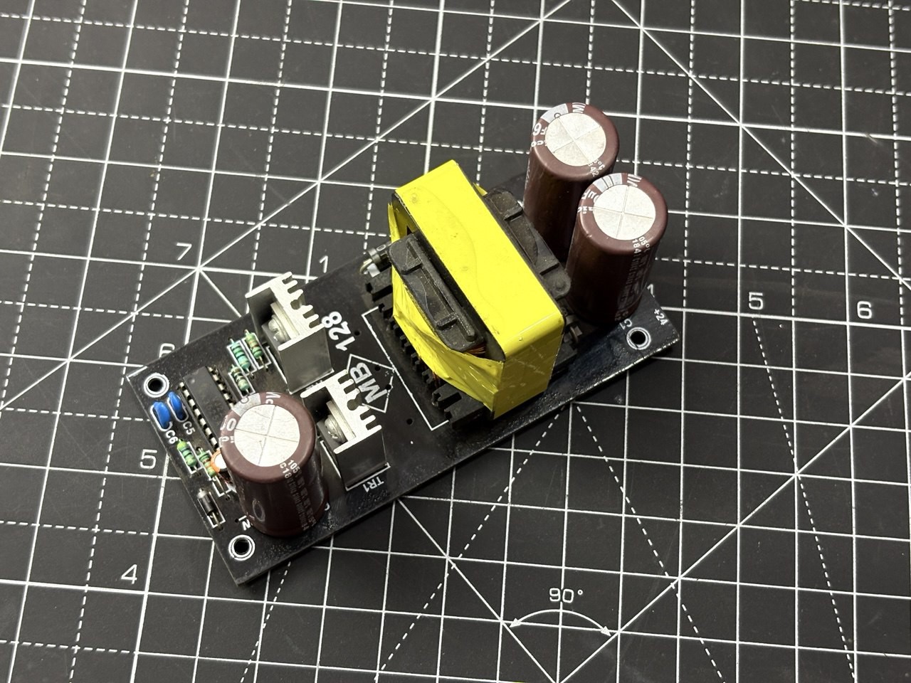
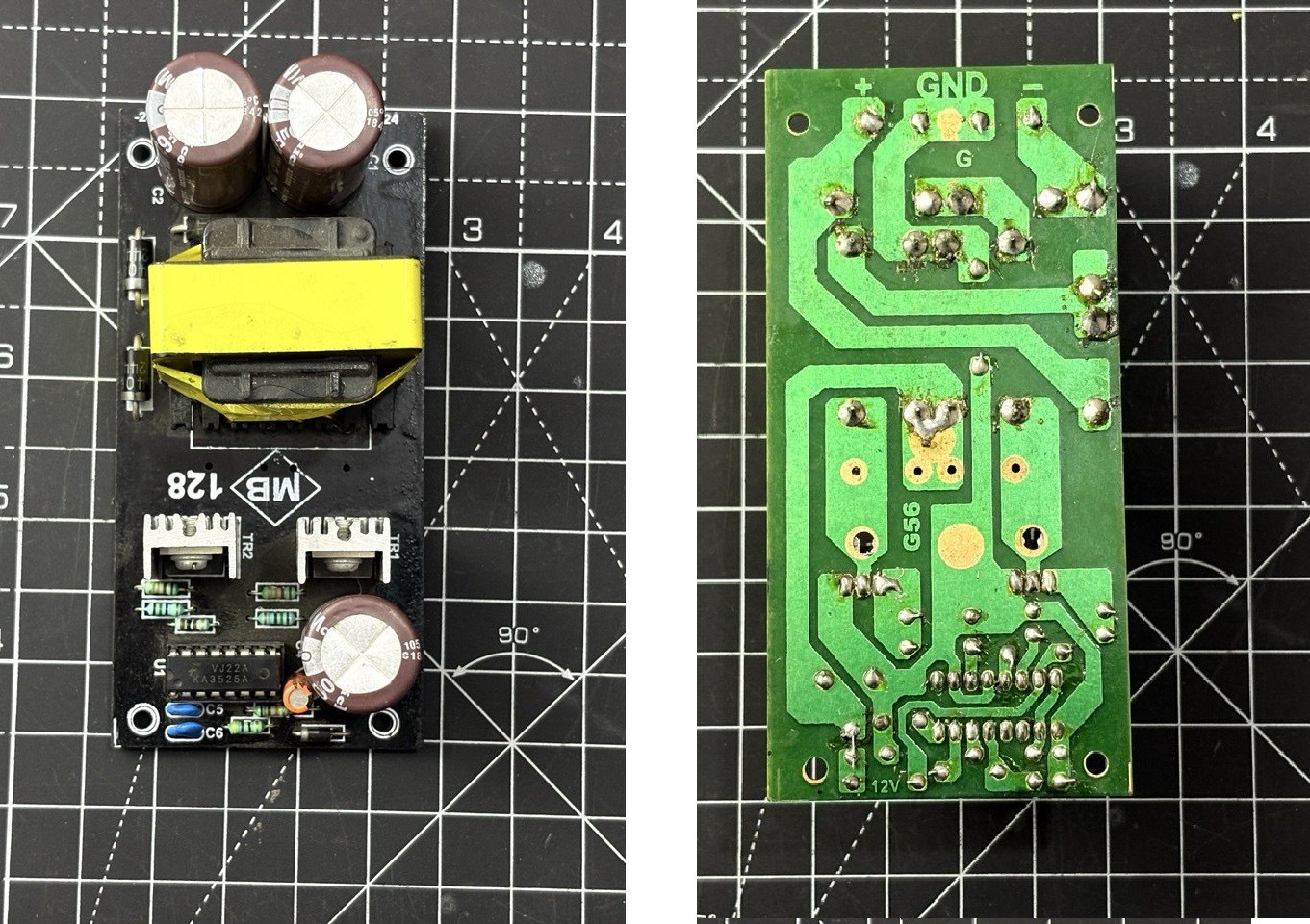
This is a compact PCB module designed for converting a single 12V DC input into a dual-rail +/-24V DC output. The target application is audio amplifiers and car audio systems. The board uses a push-pull converter topology built around the KA3525A SMPS controller IC and two IRFZ44N N-channel power MOSFETs. There's a centre-tapped transformer wound on a core mounted directly to the PCB, rectifier diodes on the secondary side, and electrolytic filter caps for the DC output.
Features:
- Input voltage: 12V DC (from car battery, lead-acid, or regulated adapter)
- Output voltage: 24-0-24V DC (dual rail, +24V and -24V)
- Output current: 5A+ capable
- Controller IC: KA3525A (Fairchild Semiconductor, 16-DIP)
- Power switches: 2x IRFZ44N N-channel MOSFETs
- Topology: Push-pull DC-DC converter
KA3525A SMPS Controller:
The KA3525A is a monolithic IC from Fairchild Semiconductor designed for pulse-width modulating regulators. It packs everything you need for a push-pull SMPS. It has:
- 5.1V band-gap reference.
- Oscillator: Set by external RT (pin 6) and CT (pin 5). Can run up to 400-430 kHz.
- Error amplifier: Differential inputs on EA(-) pin 1 and EA(+) pin 2, output on EAOUT pin 9.
- PWM comparator: Compares the error amplifier output against the oscillator ramp to generate the pulse-width modulated signal.
- Soft start: An external capacitor on this pin ramps the duty cycle up slowly at power-on, preventing voltage spikes and inrush current.
- Shutdown (pin 10): Pull this high to kill the outputs.
- Under Voltage Lockout (UVLO): Keeps the outputs off until VCC reaches 6-8V.
The maximum duty cycle per output is capped at about 45-49%. This is deliberate. In a push-pull converter, if both MOSFETs ever conduct simultaneously, you get a dead short across the supply through the transformer primary. The KA3525A's internal flip-flop and deadtime control (pin 7) ensure that never happens.
How the Converter Works:
Let me walk through the signal flow from 12V input to +/-24V output.
Step 1: PWM Generation:
The KA3525A oscillator produces a sawtooth ramp at the switching frequency set by RT and CT. The PWM comparator slices this ramp against the error amplifier output to generate the PWM signal. The internal flip-flop then alternately routes this signal to OUTPUT A and OUTPUT B two complementary drive signals, each at half the oscillator frequency, with guaranteed deadtime between them.
Step 2: MOSFET Switching:
Each output of the KA3525A drives the gate of an IRFZ44N N-channel MOSFET. These are rated for 49A drain current, 55V drain-source voltage, and just 17.5 milliohms of RDS(on). Massive overkill for this application. When OUTPUT A goes high, MOSFET A turns on and pulls one end of the transformer primary winding to ground. When OUTPUT B goes high, MOSFET B pulls the other end to ground. The centre-tap of the primary is connected to the 12V input....
Read more »
 Sagar 001
 icstation
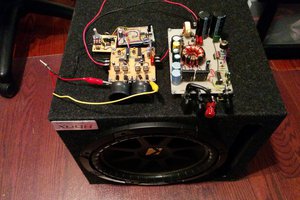
 Boolean90
 Quinn
Quinn