 Paul Horsfall
Here's a picture of my first attempt at assembling one of my ADC breakout boards:
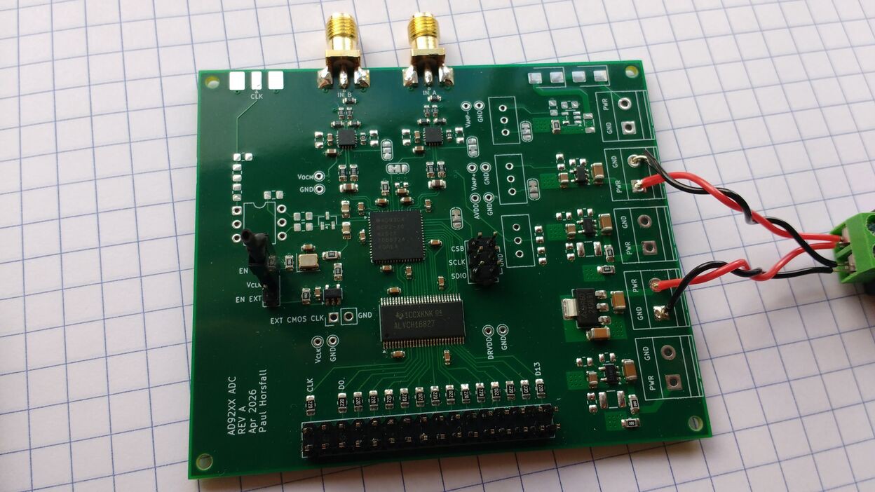
I used the hotplate method for the surface mount parts, and then hand soldered the through hole parts and SMA connectors with an iron.
This instance is populated with an AD9204 for the ADC, an 8 MHz crystal oscillator for the clock, and a pair of ADA4940 amplifiers configured for a gain of two and 50 ohm input impedance.
I've already performed a few basic checks to determine whether the board is working as expected:
- The DC voltages on the power rails look good.
- The oscillator is running.
- The ADC clock output looks good.
- I'm seeing switching on (at least some of) the data outputs.
- The input impedance of both inputs looks like 50 ohms. (This suggests the amplifiers are working.)
So far so good. The next step is to attempt to read the data coming from the ADC.
Discussions
Become a Hackaday.io Member
Create an account to leave a comment. Already have an account? Log In.