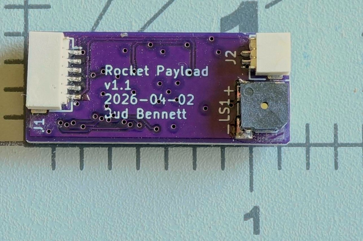
Bud Bennett
I'm not a rocket enthusiast, but I belong to a radio control club which has members who are. You can purchase commercial versions of this Payload, but I think this one is smaller and lighter weight than most others and will be much less expensive (if you don't count my labor.)
Disclaimer:
I'm using Anthropic's Claude Code to aid in writing both the firmware and application software. Without Claude this project would either: be much longer, if I had the ambition, or would not exist due to my lack of knowledge on the software side of it.
Two Payload Versions:
A "STANDARD" version with less data storage (512kb EEPROM). Records the flight parameters:
- Max thrust
- Burn duration
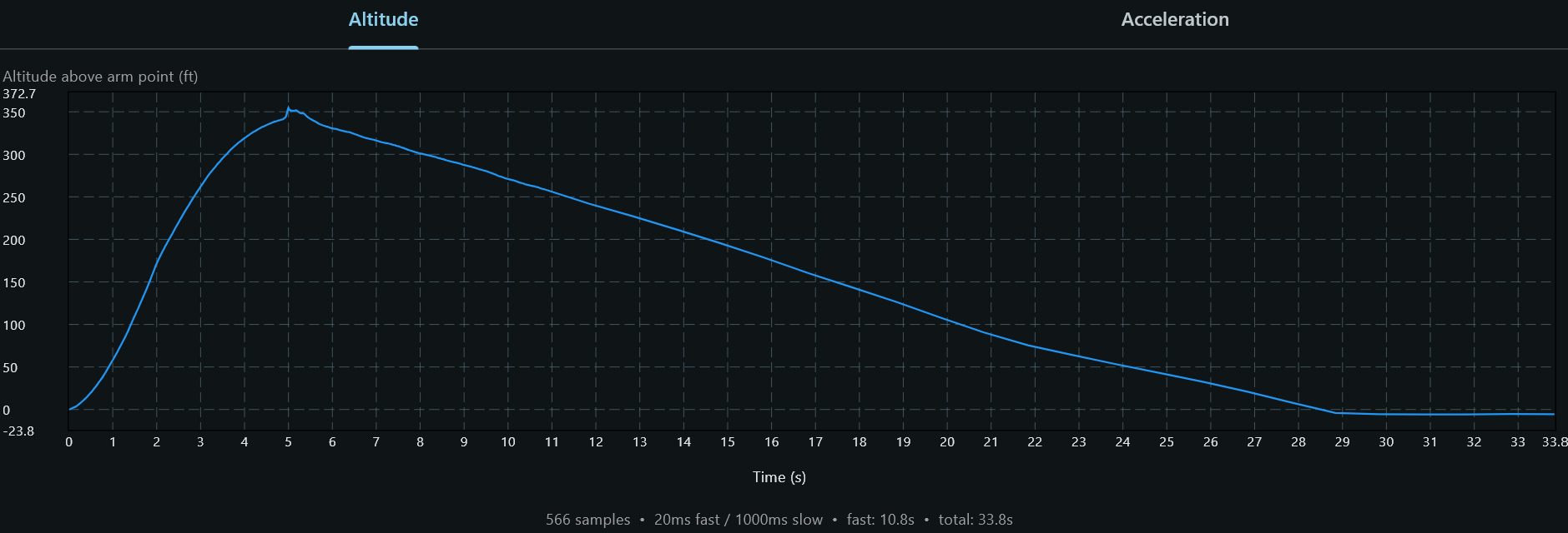
- Maximum Altitude
- Time to apogee
- Recovery time.
- Total flight time.
Real time sensor readings (barometer, accelerometer, gyro, temperature) at user selected intervals (20ms, 40ms, 80ms, 160ms) from launch detection to 5 seconds after apogee (or up to max interval set by user), then records data during recovery at 1 second intervals until landing.
A "PRO" version that has 4Mb of EEPROM. Has storage for up to 8 flights. Records the flight parameters above and the real time sensor readings from launch detection to 5 seconds after apogee (or up to max interval set by user), then records data during recovery at 1 second intervals until landing.
What it Does:
- Uses a 1S 501010 LiPo battery -- 40mAh, 5mm x 10mm x 10mm, weight: 1g.
- Sensors: BMP384/BMP390/BMP388 for altitude (pressure), LSM6DSO32 IMU for g-force (accelerometer) and rotation (gyro)
- Payload can be inserted completely into payload section of rocket and "armed" by placing strong magnet along side of rocket.
- Payload confirms arming and beeps every 5 seconds while armed. Ready for launch 5 seconds after arming.
- Rocket launch axis automatically determined when armed. Launch is detected by exceeding user specified g-force along the launch axis. Sensors sample at user selected sample rate (50Hz max.) intervals.
- After launch is detected the Payload saves the flight parameters and the flight history to EEPROM.
- After apogee + 5 seconds (or maximum fast sample duration), sensors switch to sampling at 1 second intervals.
- Landing detected after 5 seconds of unchanging altitude.
- Upon landing, Payload goes to sleep while emitting a beep every 5 seconds.
- User recovers rocket and Payload. Then disarms payload with magnet. Payload stops beeping and enters true sleep mode -- 17μA.
- The battery can be removed at this point. The data is stored in non-volatile memory.
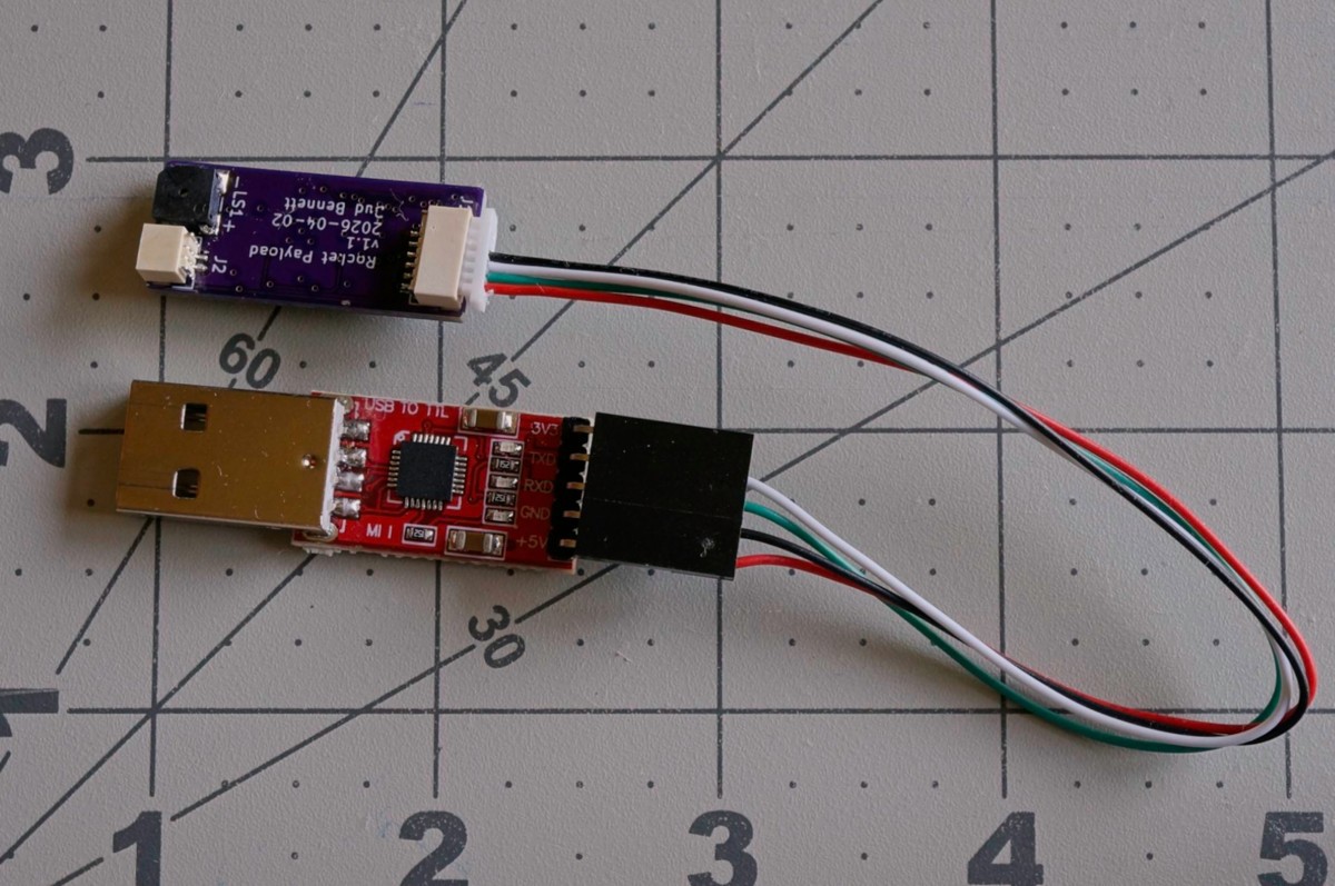
- Data is extracted when user connects Payload to USB interface and uploads data to application that displays the flight parameters/history.
Specifications:
- Supply Voltage Range: 4.2V - 3.3V (pretty much the useful voltage of a 1S (3.7V) LiPo battery.)
- Dimensions: 15mm x 40mm x 8-9mm, including battery and enclosure.
- Weight: around 5g, including battery and 3D printed enclosure.
- Runtime from 501010 battery: TBD, but should be greater than 1 hour in launch mode. Estimated max supply current < 10mA.
- Sleep/standby Duration: 50 days from fresh battery. 17μA.
- Acceleration Measurement: ±32g max, resolution 1mg.
- Gyro Measurement: up to 2000 dps full scale, TBD resolution.
- Pressure Measurement:
- Max altitude -- 27,000m/88.5k feet (300 Pa)
- Relative Accuracy -- ±0.75m (0.09 hPa)
- Resolution: ~ 1mm (0.016 Pa)
- Fast Data Record Length: 72 seconds maximum at 50Hz.
- Recovery Record Length: depends upon user selection of fast sample duration.
- On-board 1S battery charger: 20mA, ~ 2 hour charge time from fully depleted to fully charged. Charges when connected to USB.
- USB data transfer: 76800 baud UART, duplex.
- Cost for components and PCB: Around $30 for the STANDARD version, $33 for the PRO version.
Latest Schematic (v2) [as of 2026-05-23]:
(Using Kicad 10.0 now and loving the dark mode.)
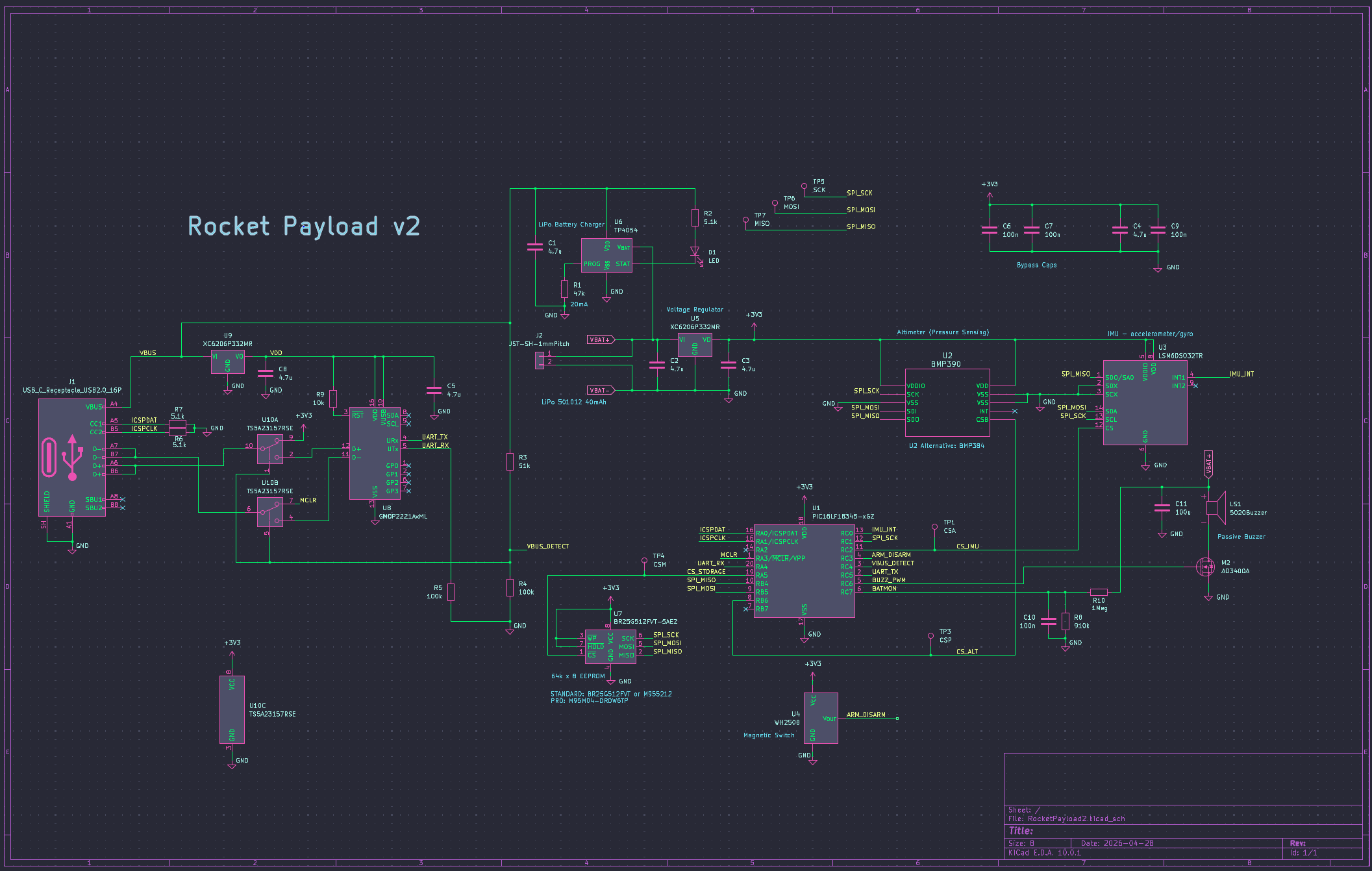
It is surprisingly simple, given the complexity of operation. Claude and I chose a PIC16LF18345 for the micro-controller. I have a PICKit4 programmer that keeps...
Read more »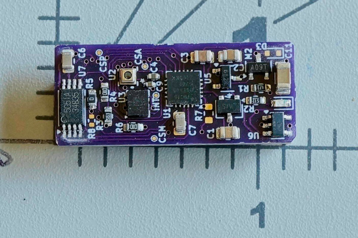
 Scott
Scott
 Kris Winer
 jeromekelty