The problem:
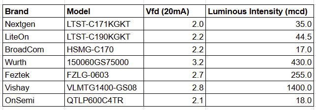
Here is a comparison for forward voltage and luminosity (mcd) at 20mA for an 0603 green LED that might be used for indicators, note the variance in forward voltage and the amount of light produced. There are also variations between different components from the same manufacturer! So picking 10mA isn't always a good option for designing indicators.
Our eyes have a logarithmic response to light.
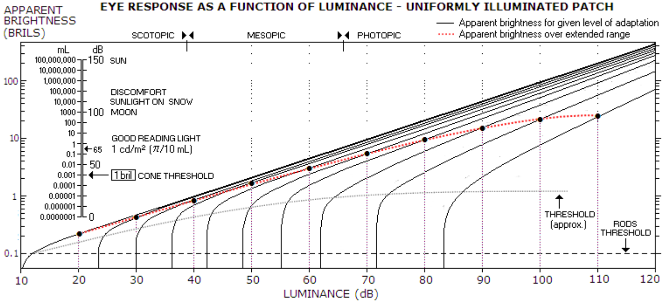
Source: https://www.telescope-optics.net/eye_intensity_response.htm
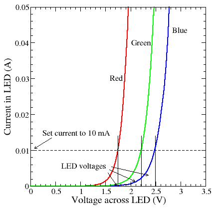
LED IV curve is non linear.
SOLUTION:
Design a device that lets you adjust the luminosity of the LED while giving me all the measurements at that brightness for whatever system voltage I'm working with. Simply put, light an LED, dim it and measure for the current to determine the current limiting resistor for a given system voltage.
The Dimming Circuit:
The original circuit was designed built around the Analog Devices LT3085 (diagram below) to provide the constant current dimming circuit. It worked well but was expensive and since it's integrated, limited to what can be done with it.
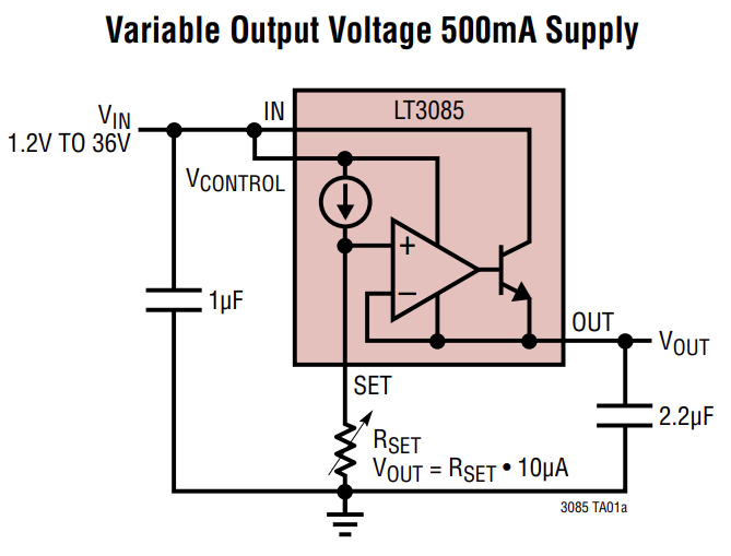
So I designed my own constant current dimming circuit.
The final design is within 70PPM error between 10-80C by compensating the thermal coefficient.
The LED forward voltage is within 0.04V of my calibrated FLUKE 87!
The curve is linear for the entire throw of the dimming potentiometer.
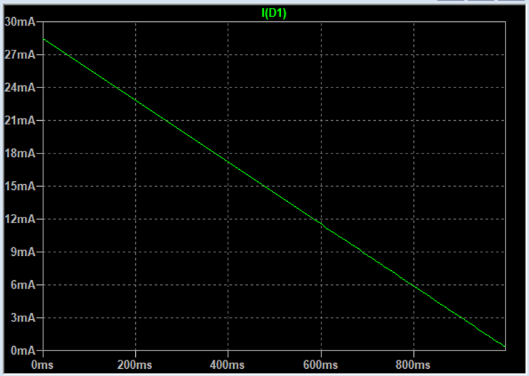
To simulate the changing resistance of a variable resistor in LTSpice. Place this in the RESISTANCE fileld: R=100k-(100k*time)
This project was challenging in many ways:
1. Originally was designed as 2 PCBs sandwiched with standoffs but my wife said it looked unfinished. I like the exposed look of it. This took my usual 2 dimensional design into 3 dimensions and took a few iterations to get right.
2. The analog design is challenging and very touchy. Many simulations and test circuits brought me to my final design.
3. To get precision from the ADC required some interesting solutions. The debugging was fun also.
4. Final design to improve accuracy and make calibration easy as well as put it into a nice case.
(this post in being worked on... adding data and notes over time)
THE JOURNEY :
The journey was long with a lot of mistakes and challenges. For instance
I was wondering why I was not getting a good reference for the ADC, and it was because I forgot to connect AVCC to the MCU. I placed a LC filter and it is now referencing an external 5V from an LDO.
Initially the software caused a lot of headaches. With INT and FLOAT math with all the divisions, cause a lot of truncation (and later, overflows). I multiplied values to increase the resolution. Then I needed to create conditional statements to output the correct values... no one wants to see 10000 Ω, so conditional if else statements now show as 10k.
There were so many things I learned along the way it's hard to list them all. The design keeps improving and hope that one day it gets into the hands of people who can use it to simplify their LED design.
The results are much better than I had originally intended and it really is a sum of many ideas I've had over the years.

It's interesting that you picked the green LEDs for your example. You'll find that you actually have two types of green LEDs in your table. The Wurth, Feztek and Vishay green LEDs have a different material which is more efficient and the forward voltage is around 3V compared to the 2+V of the others. They cost more and the colour is usually described as emerald.