G.Vignesh
-
Cuboid Design
07/23/2017 at 17:00 • 0 commentsIn the previous log I had mentioned about the hardware setup. Now let's place these in a compact box for taking perfect images by providing good lighting conditions.
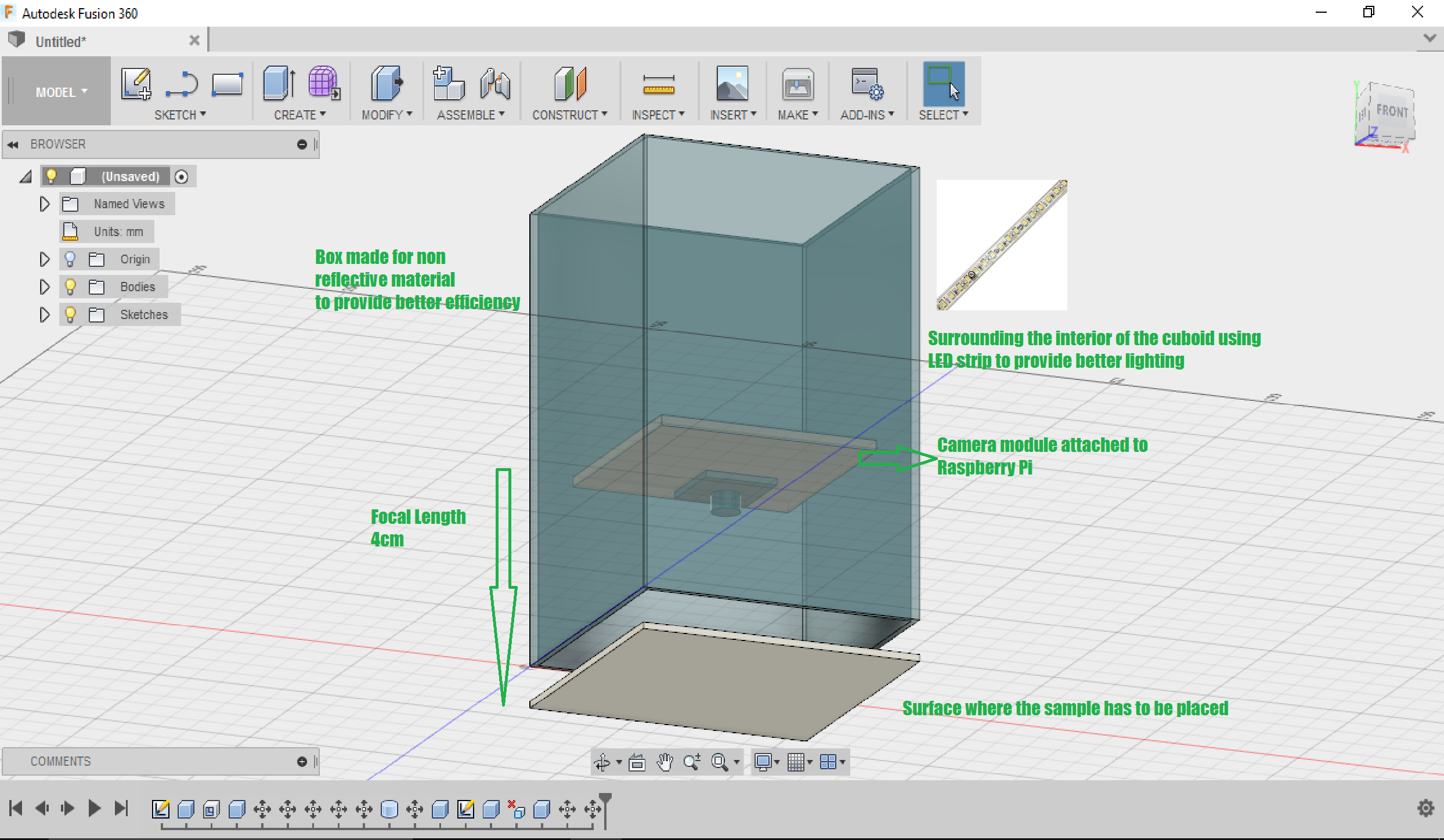
I have designed a box of dimensions 13x9x9 cm of inner thickness 2mm to accommodate all the components and is made up of non-reflective material. I have literally used a cardboard box but I would prefer a 3D printed box because of its ruggedness and spacing of the components without damage. To 3D print the box design the box according to the given specifications using a CAD software(I have used Fusion 360) and convert the file into a gcode file then print the material. The filament that can preferably used will be wood as it is a non-reflective and hard material to house the components.
LED Strips
The inner surface of the box is surrounded by LED strips upto 6cm from base. The light emitted by the LED strips must not affect the lens and hence the strips are placed 1cm above the lens of the module.
The strip is made of flexible PCB material, and comes with a weatherproof sheathing. You can cut this stuff pretty easily with wire cutters, there are cut-lines every 1.3"/3.4cm (1 LED each). Solder to the 0.1" copper pads and you're good to go. Of course, you can also connect strips together to make them longer, just watch how much current you need! We have a 5V/2A supply that should be able to drive 1 meter and a 5V/10A supply that can drive up to 10 meters (depending on use) You must use a 5V DC power supply to power these strips, do not use higher than 6V or you can destroy the entire strip.
![]()
The lens of the camera module is placed inside the box in such a way that it is 4cm from the base. A small opaque plate of thickness 2mm is placed as a base such that it does not reflect the light back to the camera.
-
Getting started with the hardware!
07/23/2017 at 13:57 • 0 commentsPreviously I had posted logs indicating the possibility of image processing for adulteration detection using software only. In the upcoming logs I will be posting updates regarding the project using the hardware and software as well.
The hardware setup is so simple that the camera module connected to a Raspberry Pi is placed inside a closed box and a LED strip is placed inside to give suitable lighting conditions such that a perfect image can be captured and could be subjected to image processing.
Raspberry Pi 3 Model B
It is a super cool mini computer that costs only 50$ and I am using this because of its infinite possibilities. It stand out from other development boards as it supports WiFi, BLE, slots for USB, HDMI interface, camera and display ports! Install the required files and software, power up and you are ready to play!
![Image result for raspberry pi camera v2]()
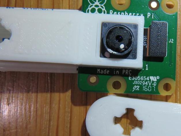
Raspberry Pi camera Version 2.1
The camera module that I have used for the project is a V2-1080p, 8 megapixel camera. I have used a normal camera and not the NoIR camera module. The NoIR effectively captures images using the IR and is mainly used for picturing images during night. On the other the normal camera can take perfect images during day or normal vision. That becomes more suitable for this project as I will be using artificial lighting.
![Image result for raspberry pi camera v2]()
This module comes with an infinite focus which means, objects at farther distance are more clearer than the near objects. The lens of the camera module has to be adjusted to preferred focal length by turning the lens either clockwise/anticlockwise. Since I require an focal length of less than 7cm I need to reduce the focal length by rotating the lens in anti-clockwise direction. I used a pair of pliers to adjust the focal length. One set was used to hold the base of the module tightly and the other was used to rotate the lens. During the process there were some scratches while using pliers but luckily the plastic region was damaged little bit and the lens was unharmed!!!
This is a risky process as one has to be careful with the pliers or they may end up in damaging the module and you may require to buy another module.
For time being I utilized the pliers and I would suggest to use this 3D printed custom made pliers for this process posted in thingiverse for safe usage.
https://www.thingiverse.com/thing:1574661
![Image result for raspberry pi camera v2 lens adjustment]()
I rotated the lens in the anti-clockwise direction upto few degrees(upto 240 degrees) until I obtained a clear picture at a focal length of 4cm!Note: Try not to rotate the lens to maximum extent which may result in unscrewing of the lens from the module and dust may get collected inside preventing us to take perfect images.
Testing
Now plug in the module to the raspberry pi with pre-installed Raspbian jesse OS and power up the Pi. If you are using it for the first time type user name as "pi" and password as "raspberry". Now open system configuration and enable camera. The system will reboot and after rebooting test whether the camera is able to take pictures.
![Image result for enabling raspberry pi camera]() To install the camera support enter the code in a terminal.
To install the camera support enter the code in a terminal.sudo apt-get update sudo apt-get install python-picamera
Now open a terminal and enter the following simple code to take a picture.
import picamera
camera = picamera.PiCamera()
camera.capture('image.jpg')
Now open the file explorer and check out the image how well it had been pictured.
Check out several features such as adjusting brightness and contrast to your image and even taking images using filters such as gray scale etc.. provided in the raspberry pi documentation.
https://www.raspberrypi.org/documentation/usage/camera/python/README.md
The hardware part is set up and lets place these in a suitable closed environment such that all the components are placed in a compact box and for better lighting conditions....
-
Testing of wheat flour sample
04/23/2017 at 18:29 • 0 commentsWheat flour is a powder made from the grinding of wheat used for human consumption. More wheat flour is produced than any other flour.[not verified in body] Wheat varieties are called "soft" or "weak" if gluten content is low, and are called "hard" or "strong" if they have high gluten content. Hard flour, or bread flour, is high in gluten, with 12% to 14% gluten content, and its dough has elastic toughness that holds its shape well once baked. Soft flour is comparatively low in gluten and thus results in a loaf with a finer, crumbly texture. Soft flour is usually divided into cake flour, which is the lowest in gluten, and pastry flour, which has slightly more gluten than cake flour.
Type adulterant used and its testing
Conventional method
Chalk powder is the commonly used adulterant in the wheat flour. It can lead to several health problems such as diarrhea, stomach disorders etc. It is generally used by sellers to improve the quantity of the wheat flour and to bargain at a larger scale. There are several chemical / physical methods for testing. One such method has been listed below.
![Image result for wheat flour adulteration]()
Proposed method
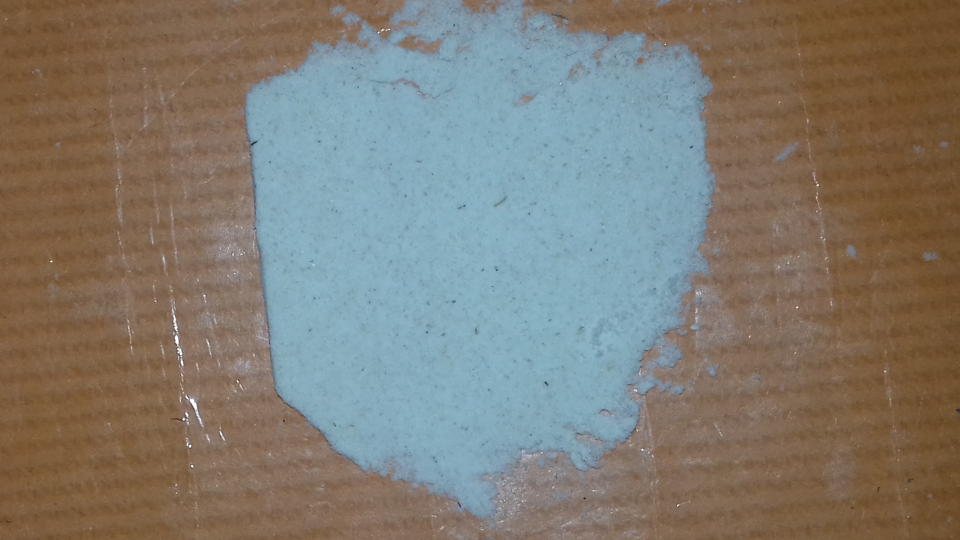
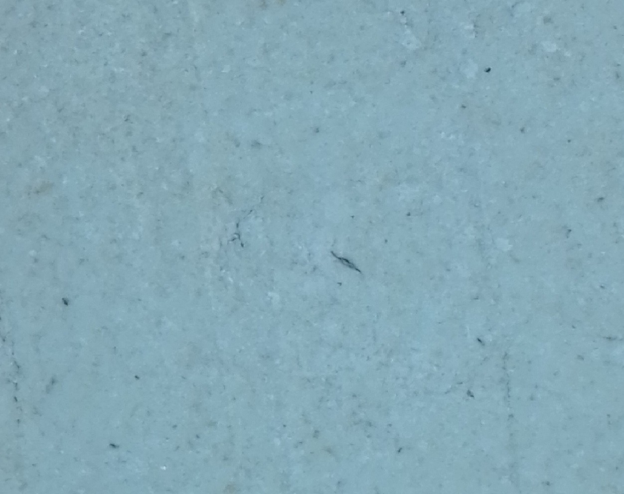
Pure wheat flour sample is placed on a surface as a thin film and pictured.
![Thin film of pure wheat flour sample]()
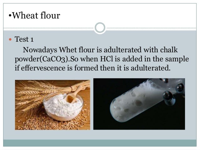
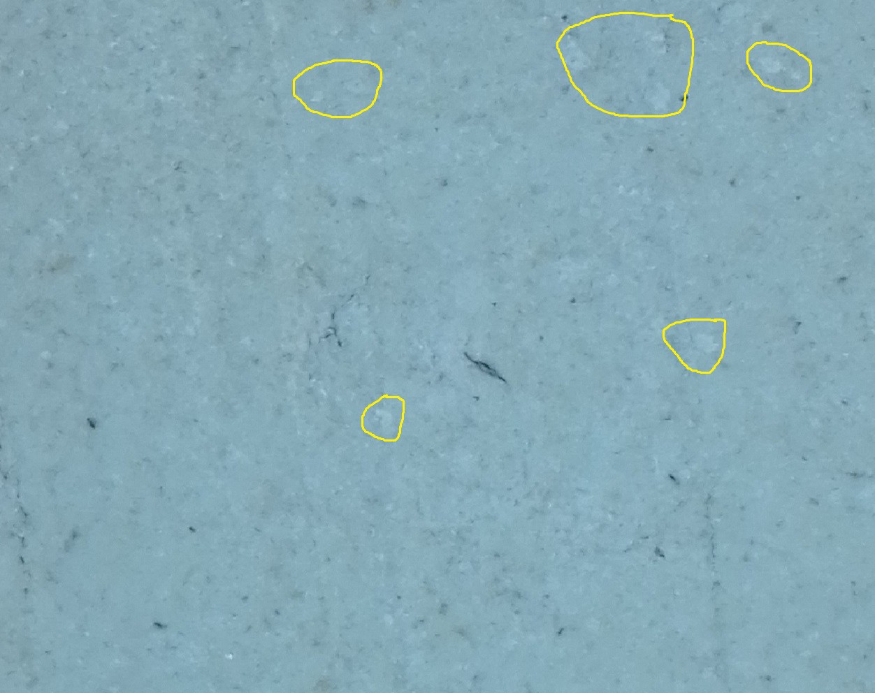
Then it is adulterated with 20% of chalk powder.
![]()
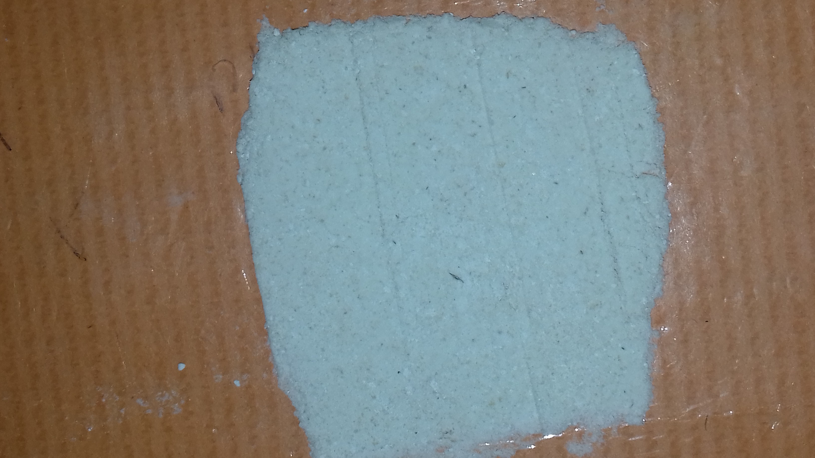
The next step is to process these images and use it to compare with that of adulterated ones. Hence I used matlab software to process the images. The below image represents the high resolution image of the pure wheat sample.
![Pure wheat sample]()
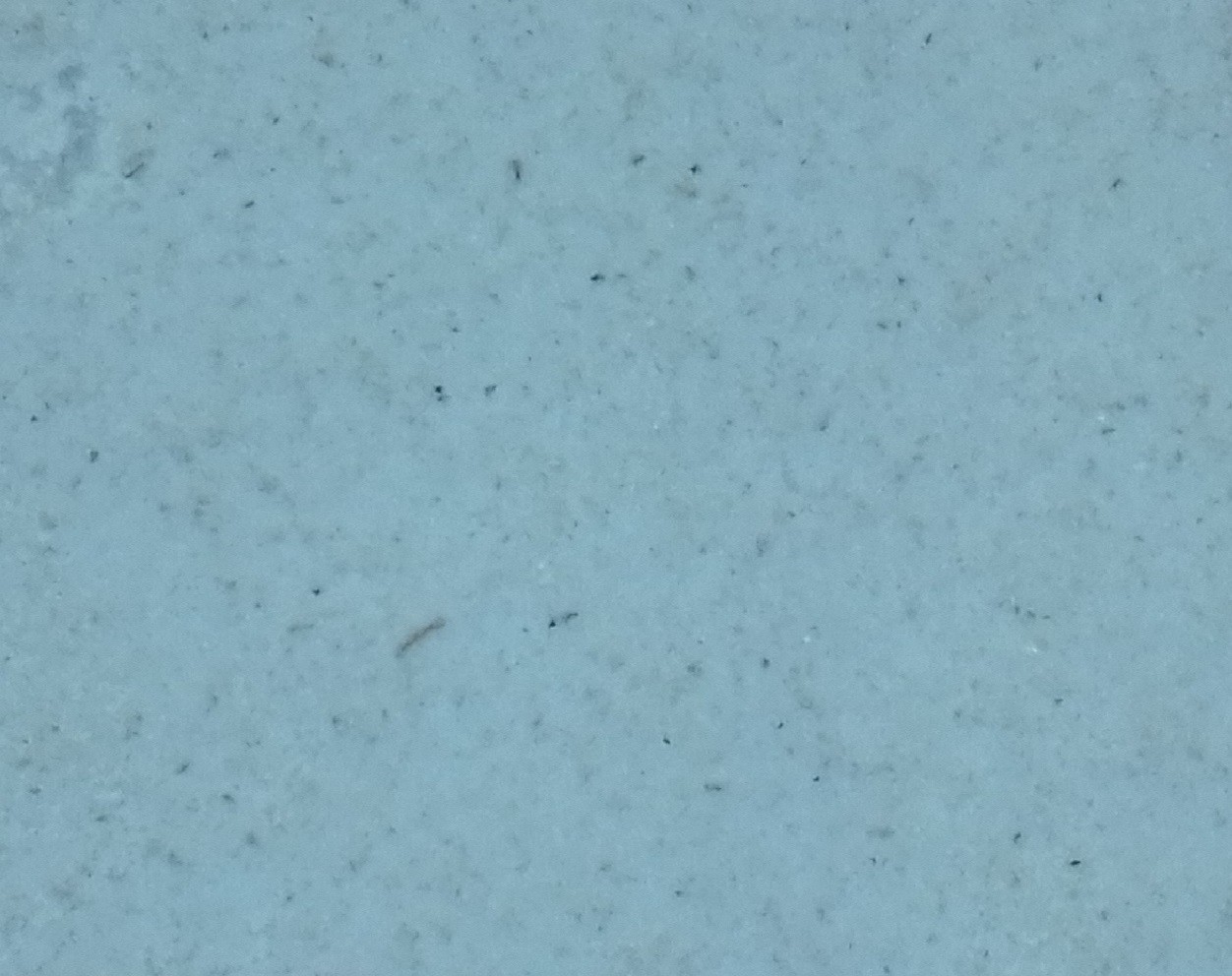
The below image represents the high resolution picture of adulterated sample.
![]()
We can easily distinguish the some of the chalk powder substrates in the wheat flour sample when we take a closer look at the the above sample. Chalk powder is appears more whiter than the actual wheat flour sample.
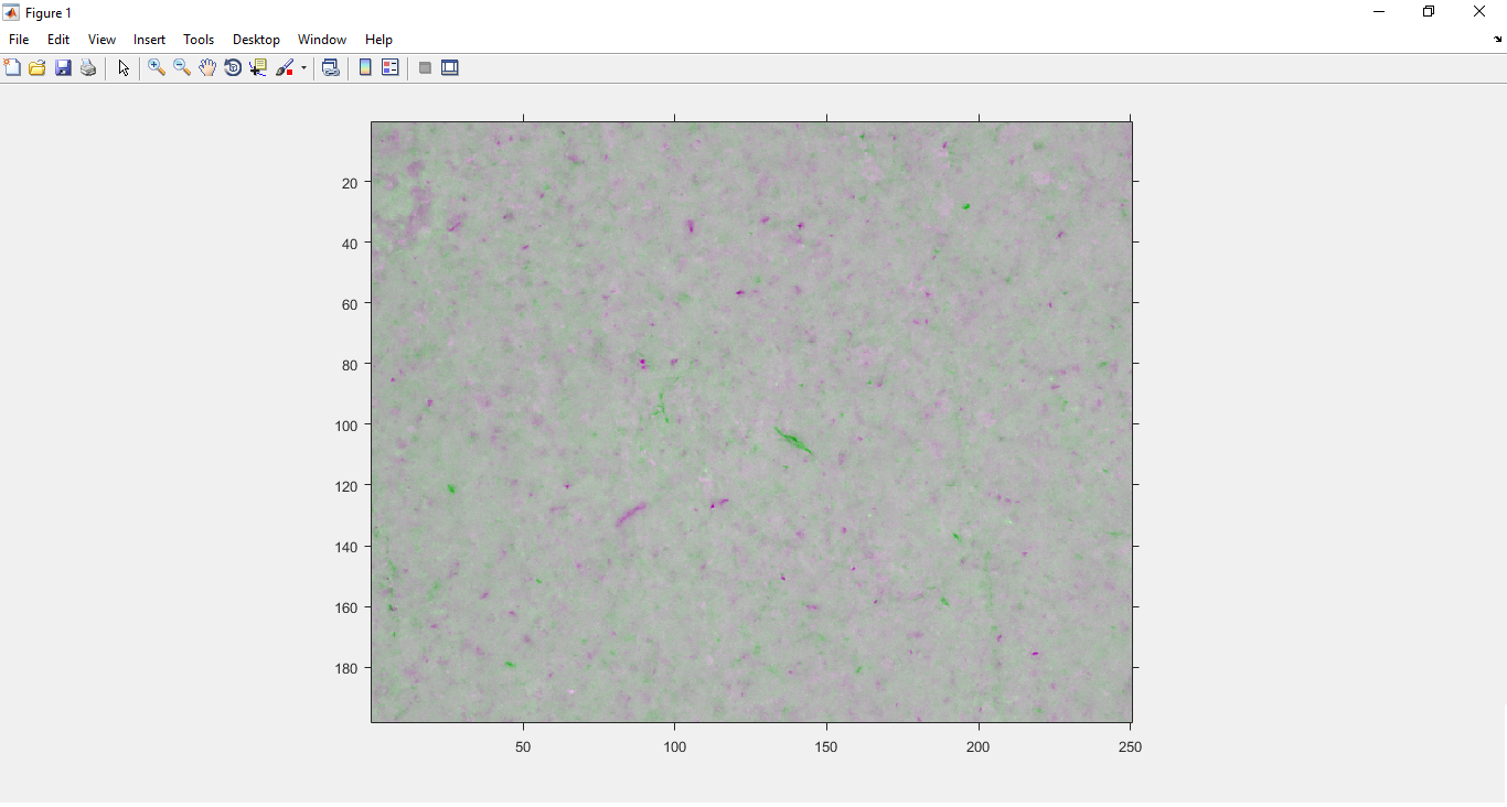
To compare this adulterated sample with that of the pure sample requires only few lines of code. First import the images in the Matlab software and in the command window type the below mentioned code.![]()
A = imread('A.jpg');
B = imread('B.jpg');

RA = imref2d(size(A),0.2,0.2);

RB = imref2d(size(B),0.2,0.2);

figure;

hAx = axes;

imshowpair(A,RA,B,RB,'Scaling','independent','Parent',hAx);
This will provide a output image which can be able to find the differences between the images and to interpret the results quickly.
The light purple colour patches indicates the darker regions/ highlighted regions that were present in pure sample image when compared to adulterated one. This effectively means that the adulterated chalk powder are indicated as purple patches. The green colour indicates the contrast of second image over the first one and it need not taken into account. So using the above image we can interpret that the wheat flour sample has been adulterated with 20% of chalk powder.![]()
-
Getting started with image processing
04/23/2017 at 17:44 • 0 commentsIn imaging science, image processing is processing of images using mathematical operations by using any form of signal processing for which the input is an image, a series of images, or a video, such as a photograph or video frame; the output of image processing may be either an image or a set of characteristics or parameters related to the image.[1] Most image-processing techniques involve treating the image as a two-dimensional signal and applying standard signal-processing techniques to it. Images are also processed as three-dimensional signals with the third-dimension being time or the z-axis.
Image processing usually refers to digital image processing, but optical and analog image processing also are possible.
Image processing can also be used to find out the differences between two images. Hence it can be used to differentiate a sample from a pure one and can be used to analyze the results with ease. Before experimenting with the hardware & machine learning part, I have tried to analyze different samples of adulterated substances in a trial and error method. I have experimented by simply analyzing impure sample with that of a pure sample. There are lot of software that support image processing but right now I have used MATLAB R2017a version.
![Image result for matlab 2017a image processing]()
This new version comes with extra features such as image enhancement, image segmentation,image transform, image analysis, geometric transformation and image registration, image processing and computer vision, feature extraction, stereo vision, optical flow, color profile, image analysis, image thresholding, edge detection, image registration, ransac, pattern recognition, affine transformation, lab color etc.![Related image]()
Image Processing Toolbox™ provides a comprehensive set of reference-standard algorithms and workflow apps for image processing, analysis, visualization, and algorithm development. One can perform image segmentation, image enhancement, noise reduction, geometric transformations, image registration, and 3D image processing.
Image Processing Toolbox apps can be used to automate common image processing workflows. One can interactively segment image data, compare image registration techniques, and batch-process large data sets. Visualization functions and apps can be used to explore images, 3D volumes, and videos; adjust contrast; create histograms; and manipulate regions of interest (ROIs).
We can easily accelerate algorithms by running them on multicore processors and GPUs. Many toolbox functions support C/C++ code generation for desktop prototyping and embedded vision system deployment.
AI based Adulteration Detector
To determine the type and amount of adulteration in a given substance using Image Processing.


 To install the camera support enter the code in a terminal.