Patrick Van Oosterwijck
-
It moves!
07/18/2017 at 20:35 • 0 commentsI hooked up my prototype driver to the pan/tilt stage and valve to test the complete system, and it's working! Driver code for the Raspberry Pi has been started and is available in GitHub. Here's a little video of the functionality thus far:
Although this doesn't have wheels or wings, and doesn't walk, the description of this Hackaday Prize round says: "Build something that moves." Well, this moves! :) So I entered it. It may not be your typical robot, but the goal is to create an automatic robotic sprinkler after all. And if you don't agree, be careful or you might get sprinkled! :)
-
Driver prototype!
07/14/2017 at 22:50 • 0 commentsI finally found the time to put the first prototype of the driver PCB together, and surprisingly, it actually works! \o/
Well, it didn't right away. It looks like the reflow of the PCB failed to connect one pin on the buck converter, the feedback pin. The buck converter is supposed to produce 5V power for the Pi from the 24VAC input. With the feedback connection missing, it instead produced 37V DC on the 5V output. Yikes! Am I glad I decided to test the output voltage before connecting it to a Pi! :)
Once that connection was fixed, the supply part worked. I'm actually very surprised that the 22 uF / 6.3V output capacitors survived the ordeal.
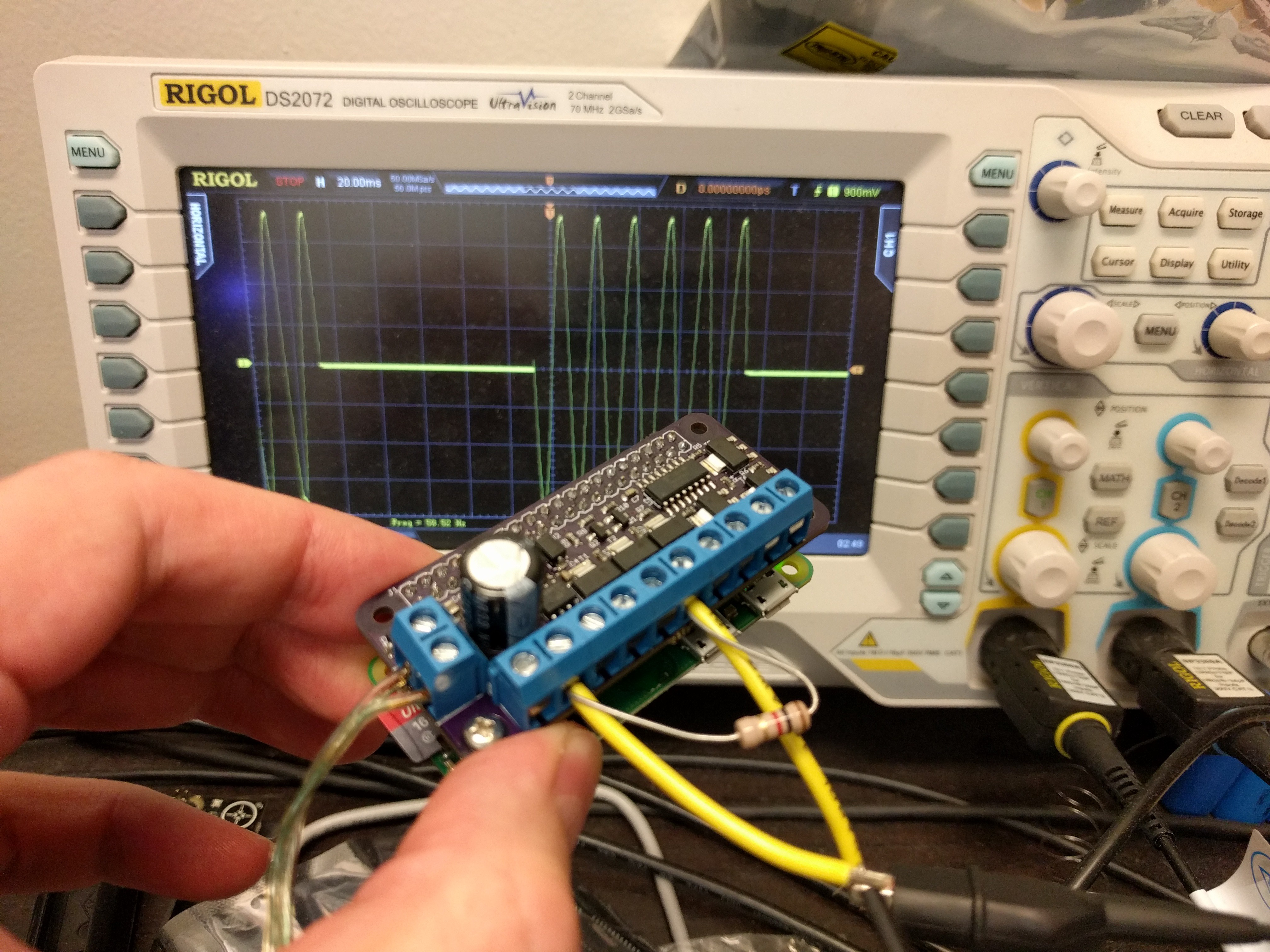
Then it was time to hook up a Pi and a load, and test whether the whole SPI driven shift register with zero cross latching scheme actually works. I followed the instructions in this post (except that the spidev library is actually in the repo now) and wrote a quick test that would turn the first output on and off every 100 ms:
while 1:
    spi.xfer([0x00])
    time.sleep(0.1)
    spi.xfer([0x02])
    time.sleep(0.1)
And here is the result:![]()
It's working beautifully! The load gets nicely switched at the zero crossings. :)
Next, it's time to hook up the pan/tilt stage and write a little control library.
-
Attaching the hose
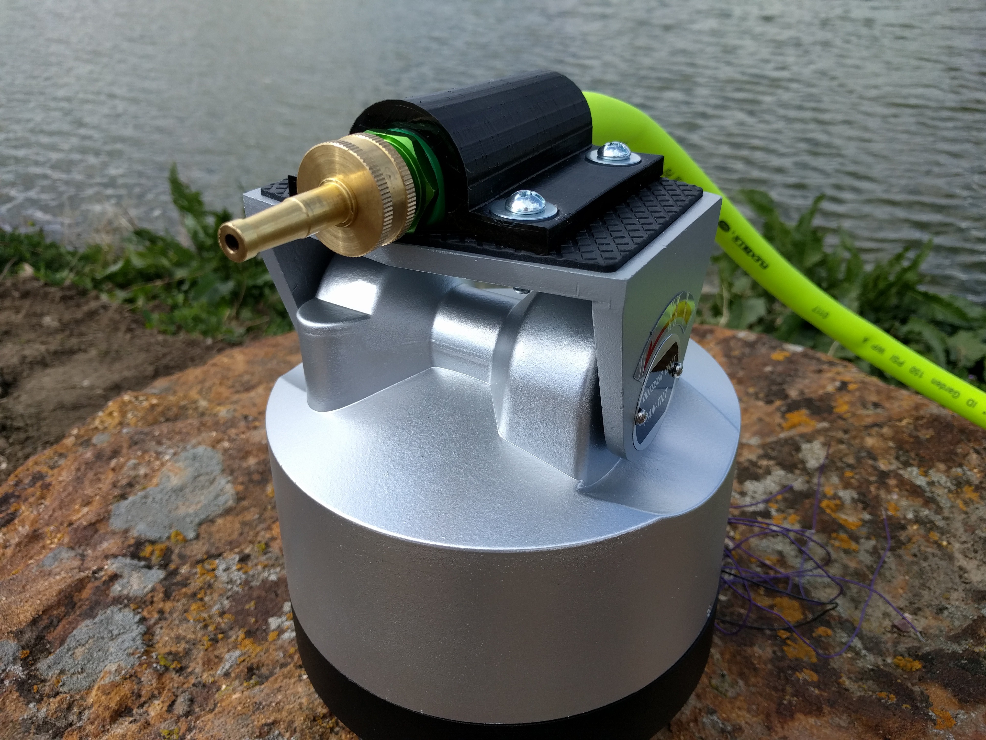
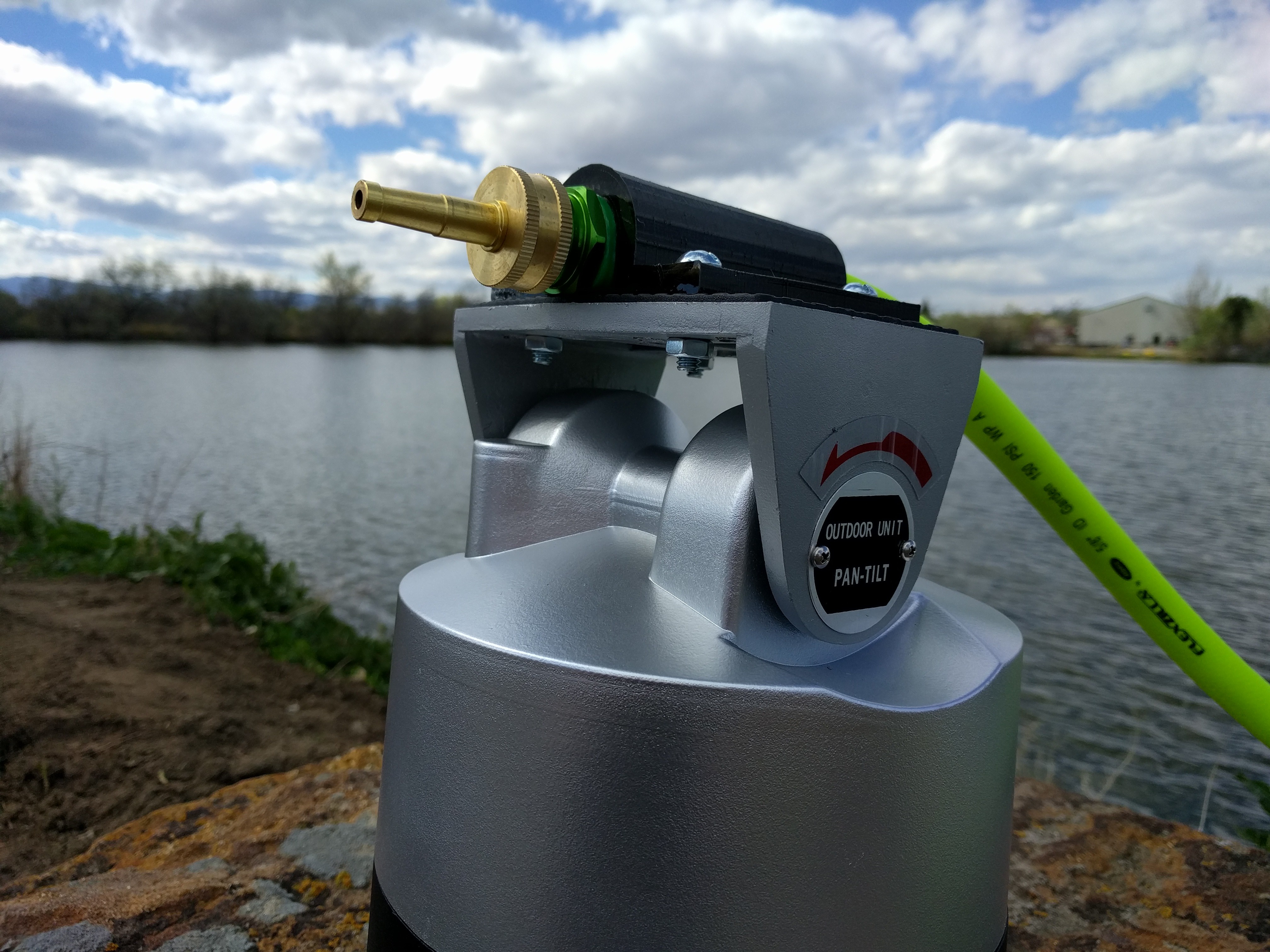
05/01/2017 at 22:35 • 0 commentsHaving the 3D printed clamp, I needed to put it together to check how it worked with the hose. I used 4x 1/4", 1" length bolts with nuts and washers to protect the plastic from friction.
![]()
![]()
I really like how this turned out!
Now I have to wait for my PCBs and components to come in to build the driver and see how it works to control this from a Raspberry Pi. Meanwhile I can also start looking at how to add the valve to this assembly in the best way.
-
Hose clamp and driver PCB
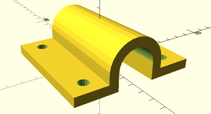
04/29/2017 at 04:46 • 0 commentsI needed a way to clamp the garden hose on to the pan/tilt stage. While it would have been possible to use some metal strap or other standard clamp, I decided it would be neater to 3D print a custom clamp. It also gave me an excuse to design a 3D model. :)
I don't do this very often, but when I do, I prefer to use OpenSCAD, since I'm used to programming. As far as models goes it's very simple:
![]()
The code is in the files section. It uses variables so that you can alter the inner diameter at either end, wall thickness, base size etc.
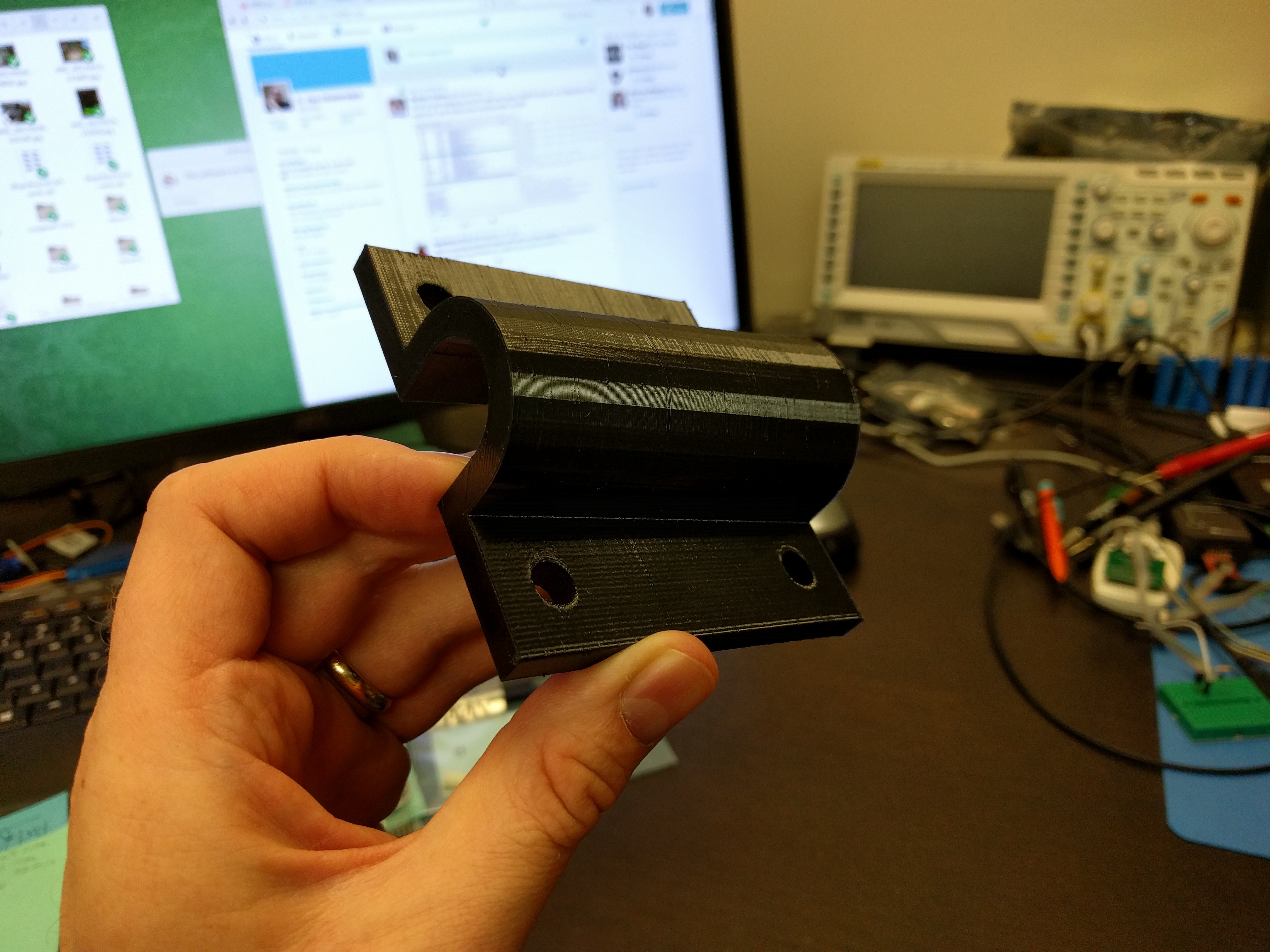
Here is how it looks when printed:
![]()
Very happy with the result, it fits great and uses nice semi-flex material. Next I need to get some bolts to put it all together.
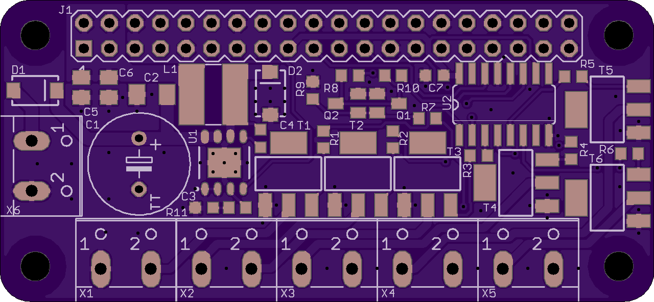
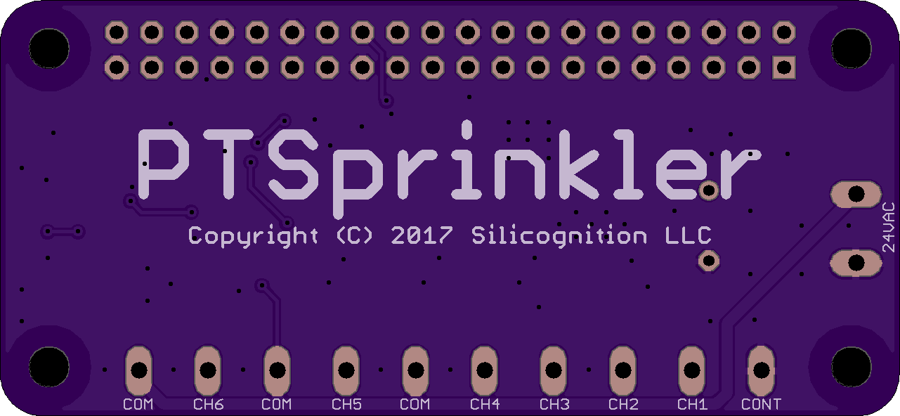
I also designed the circuit and PCB I'll use to drive the pan/tilt stage and valve from a Raspberry Pi Zero W. I seem to like to make my life difficult by trying to cram too much into too small a PCB. :) In this case I wanted it to fit in the size of a Pi Zero.
The circuit has a shift register connected to the Pi SPI, and a zero cross detection circuit that latches the received bits to drive 6 TRIACs. It also takes the 24VAC and converts it to 5VDC for the Pi. Eagle files are in the files section, but beware, this is as of yet untested!
![]()
![]()
The project is also shared on OSH Park.
Next I'll be assembling the hose to the pan/tilt stage and then it's waiting for the PCBs to come in.
-
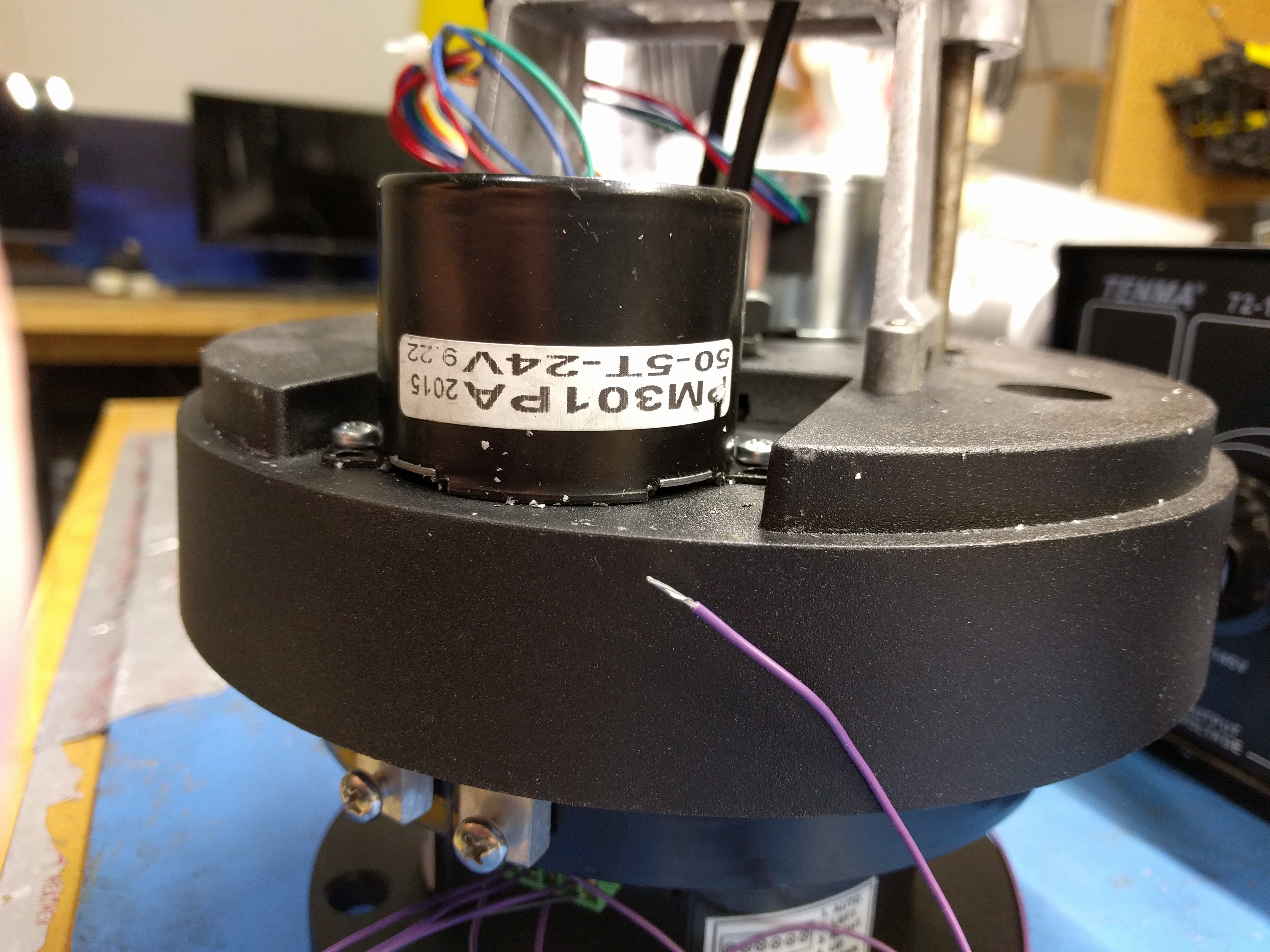
Dissecting the pan/tilt stage
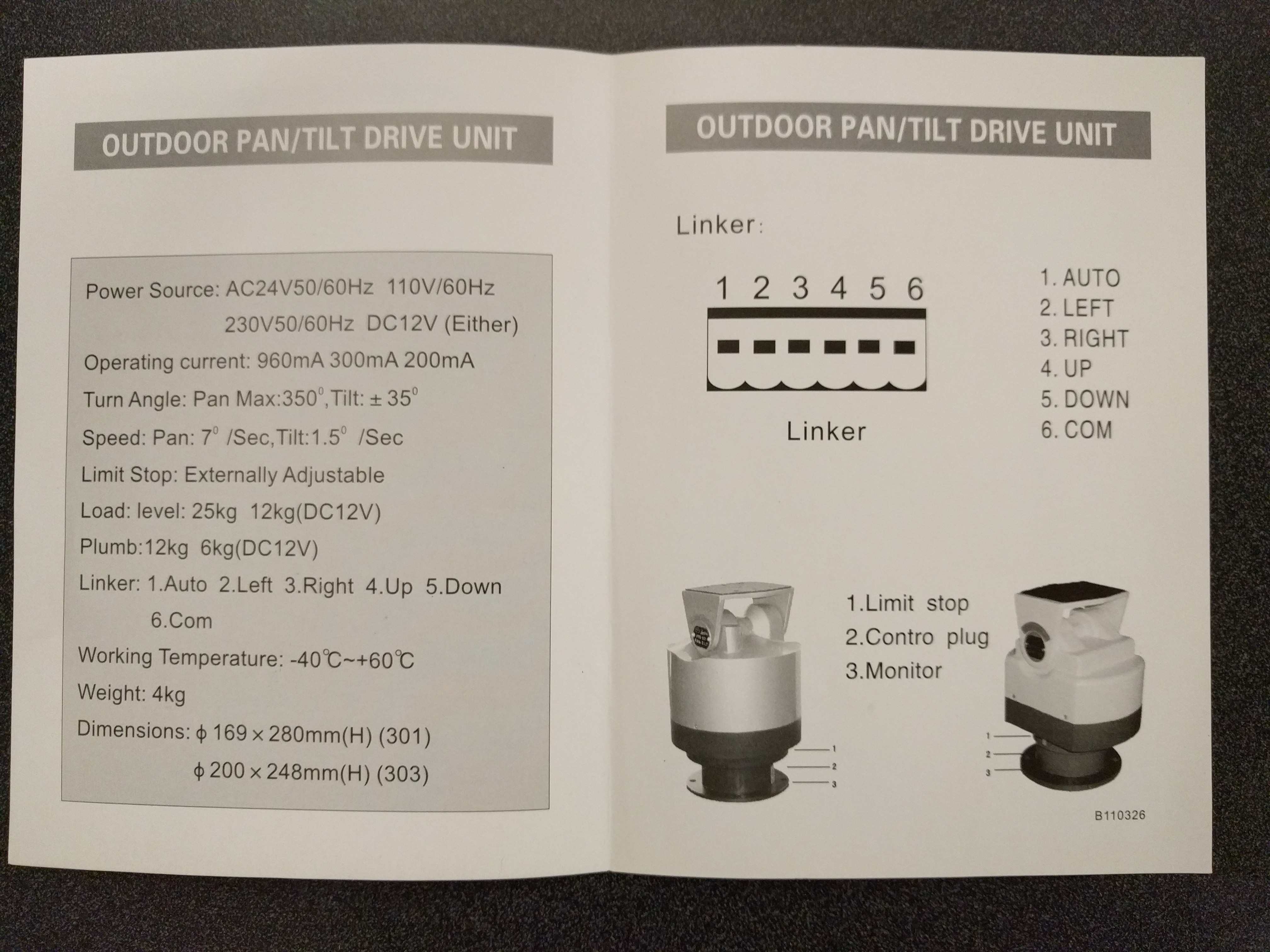
04/20/2017 at 18:25 • 0 commentsI decided to play with the pan/tilt stage, below is the little bit of info that came with the device:
![]()
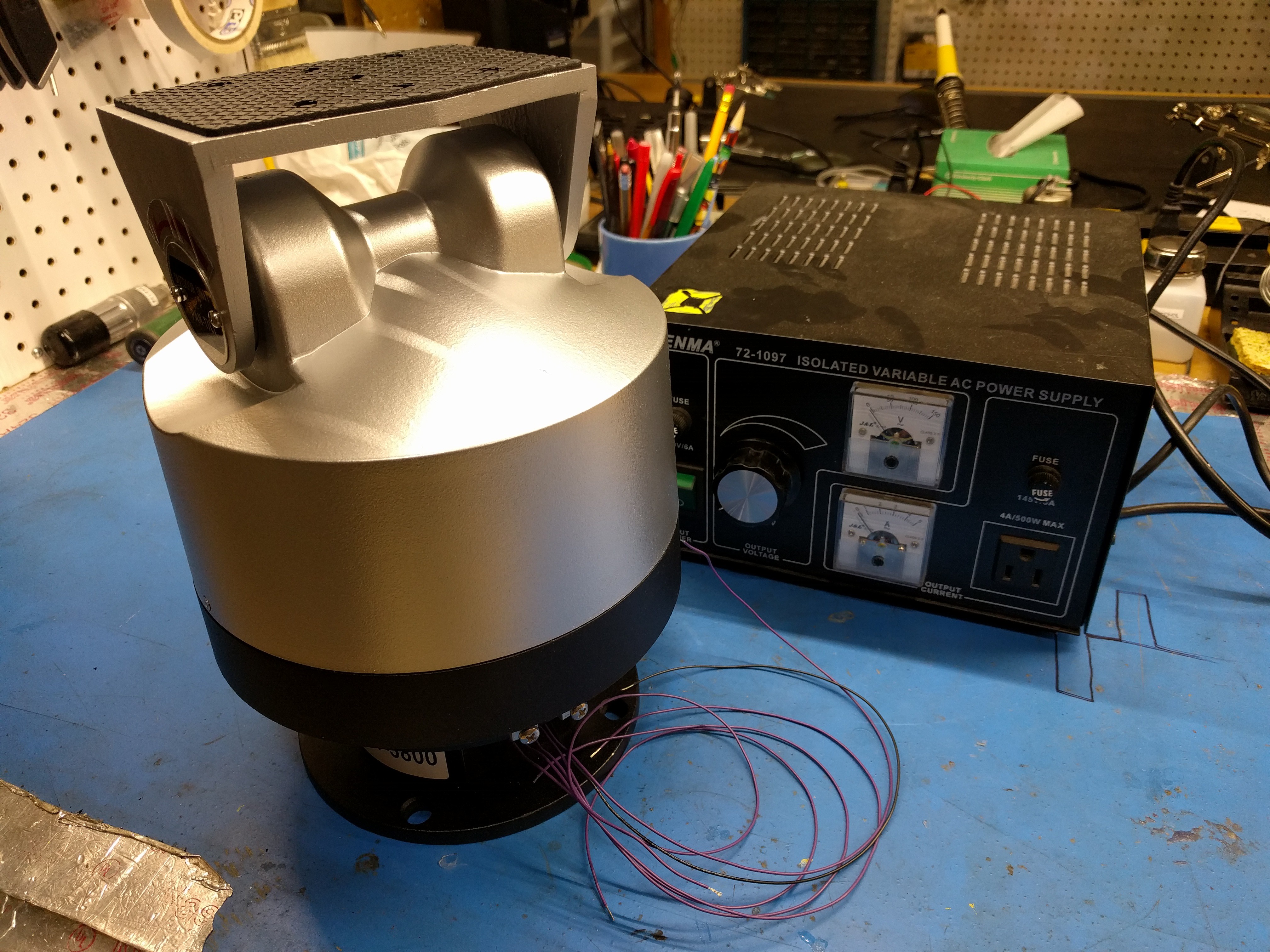
Then I did some testing to see how it all behaves. At Tinkermill I have access to a nice isolated AC supply to do this:
![]()
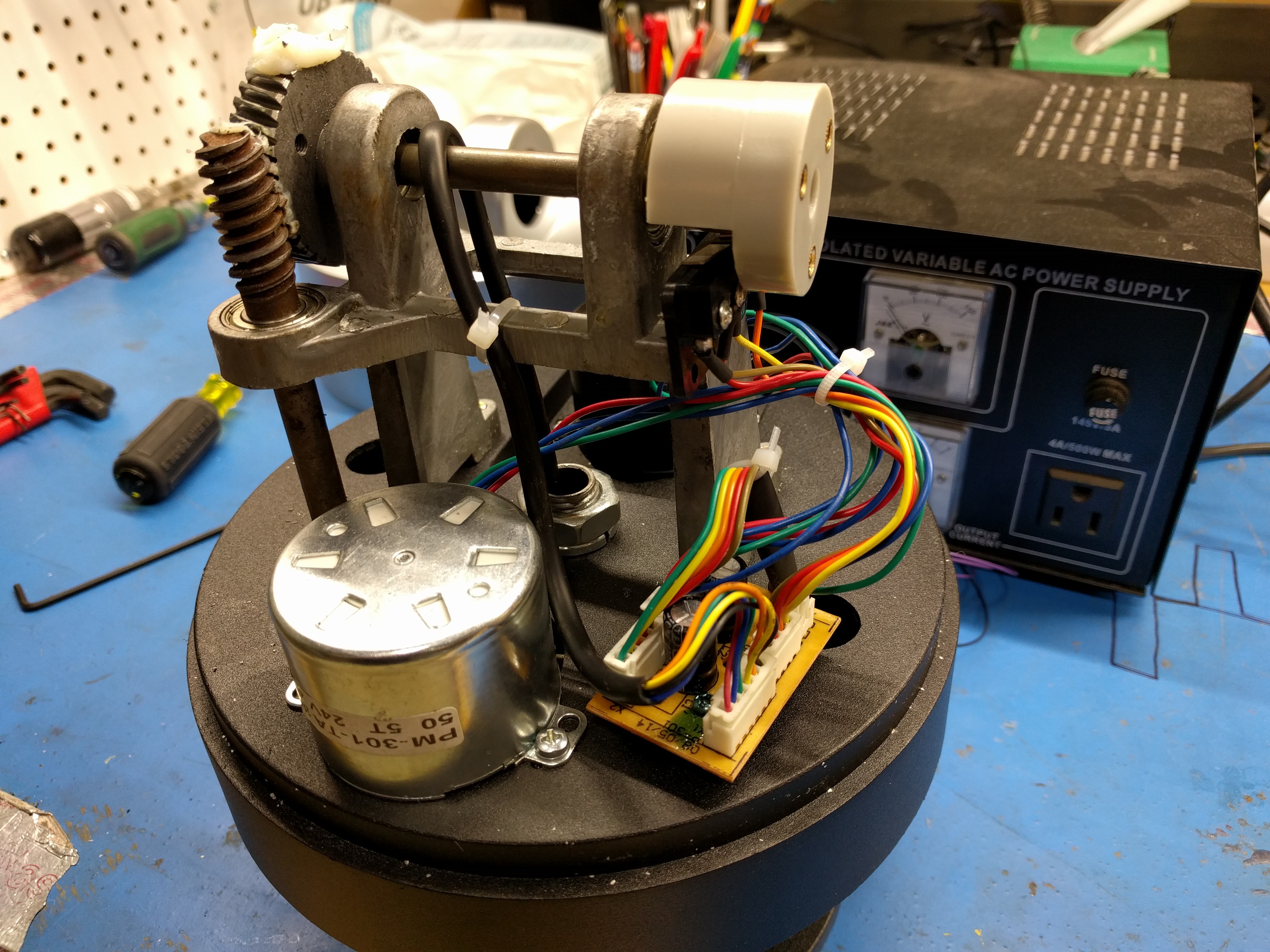
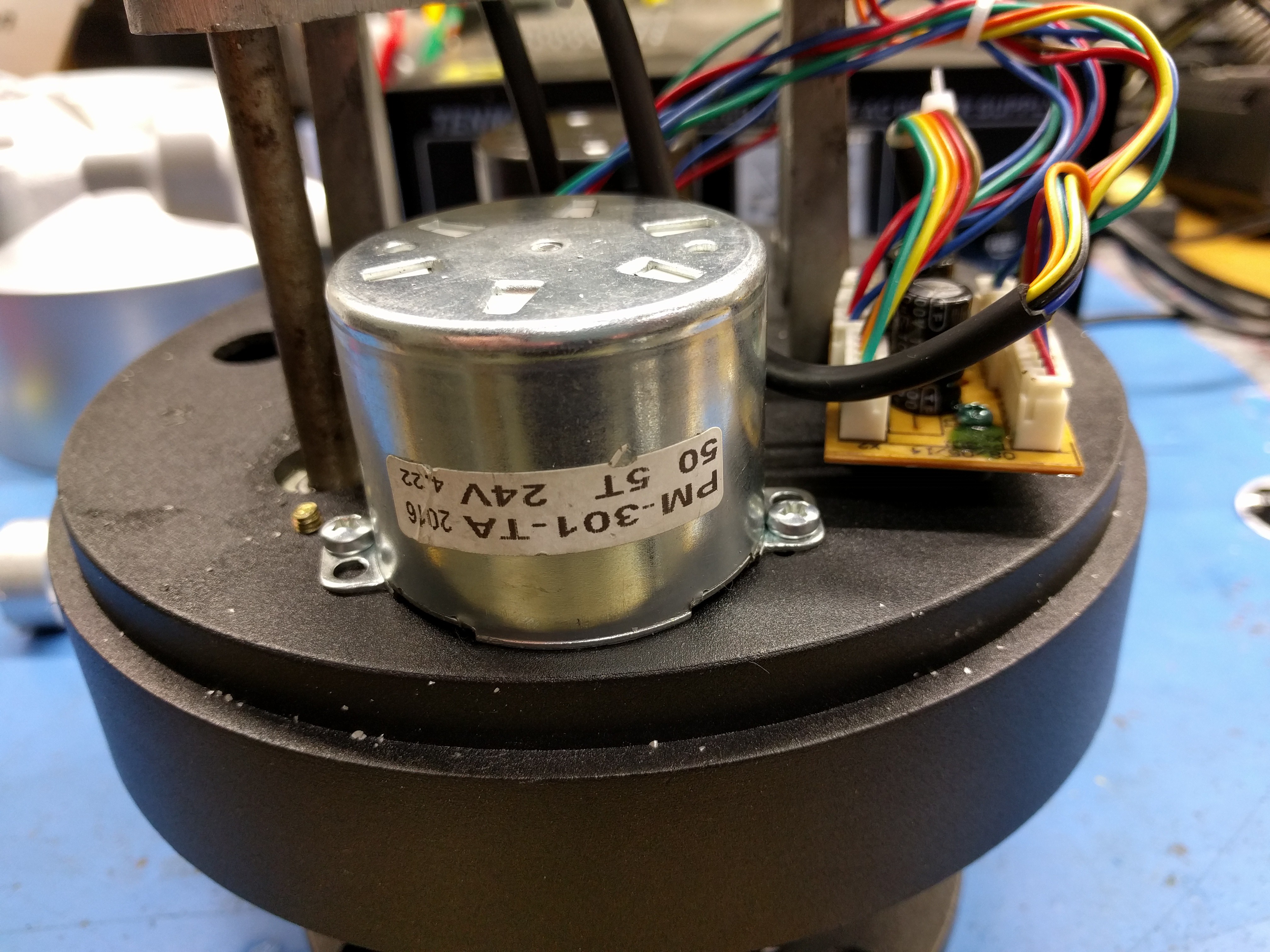
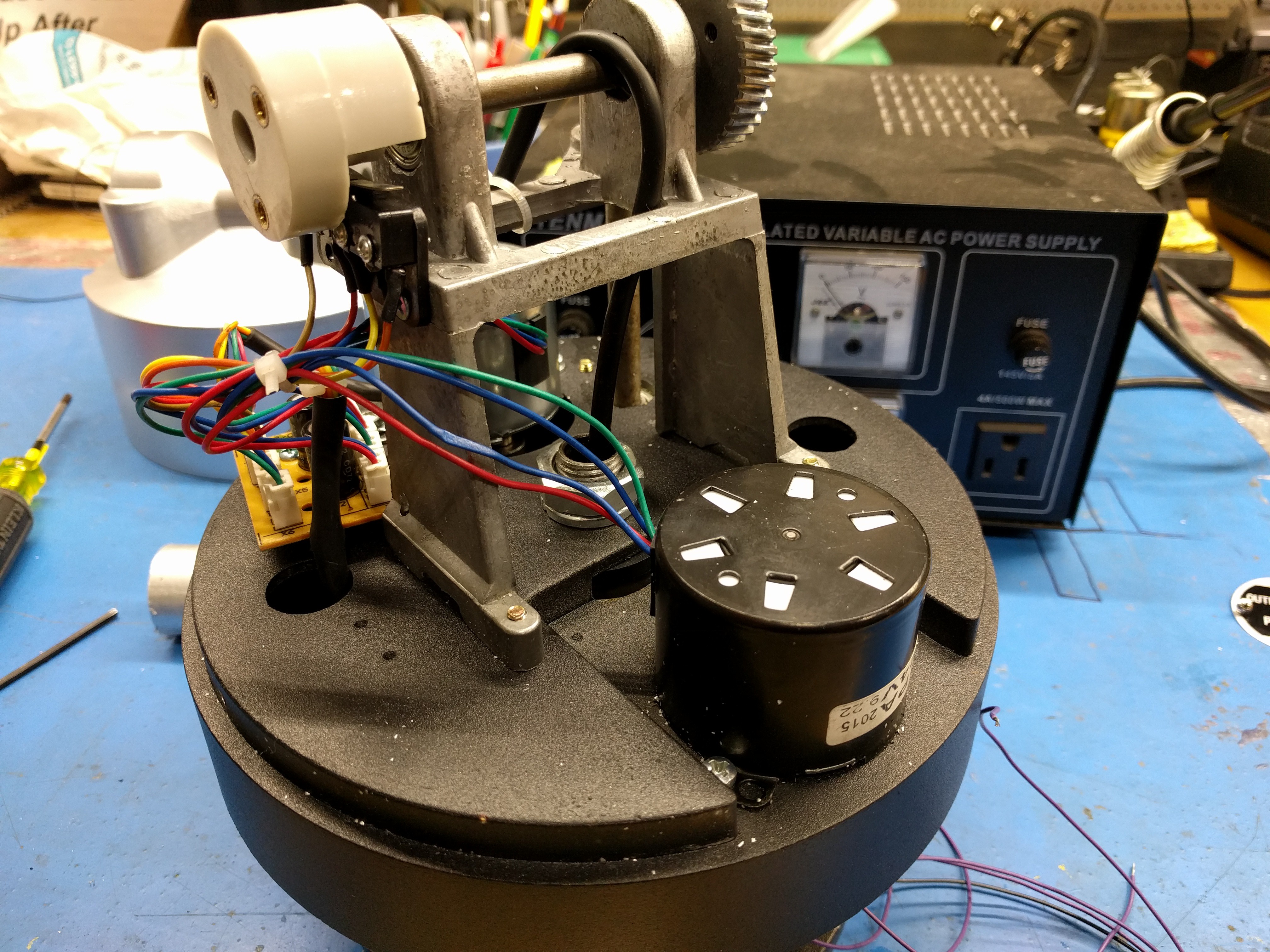
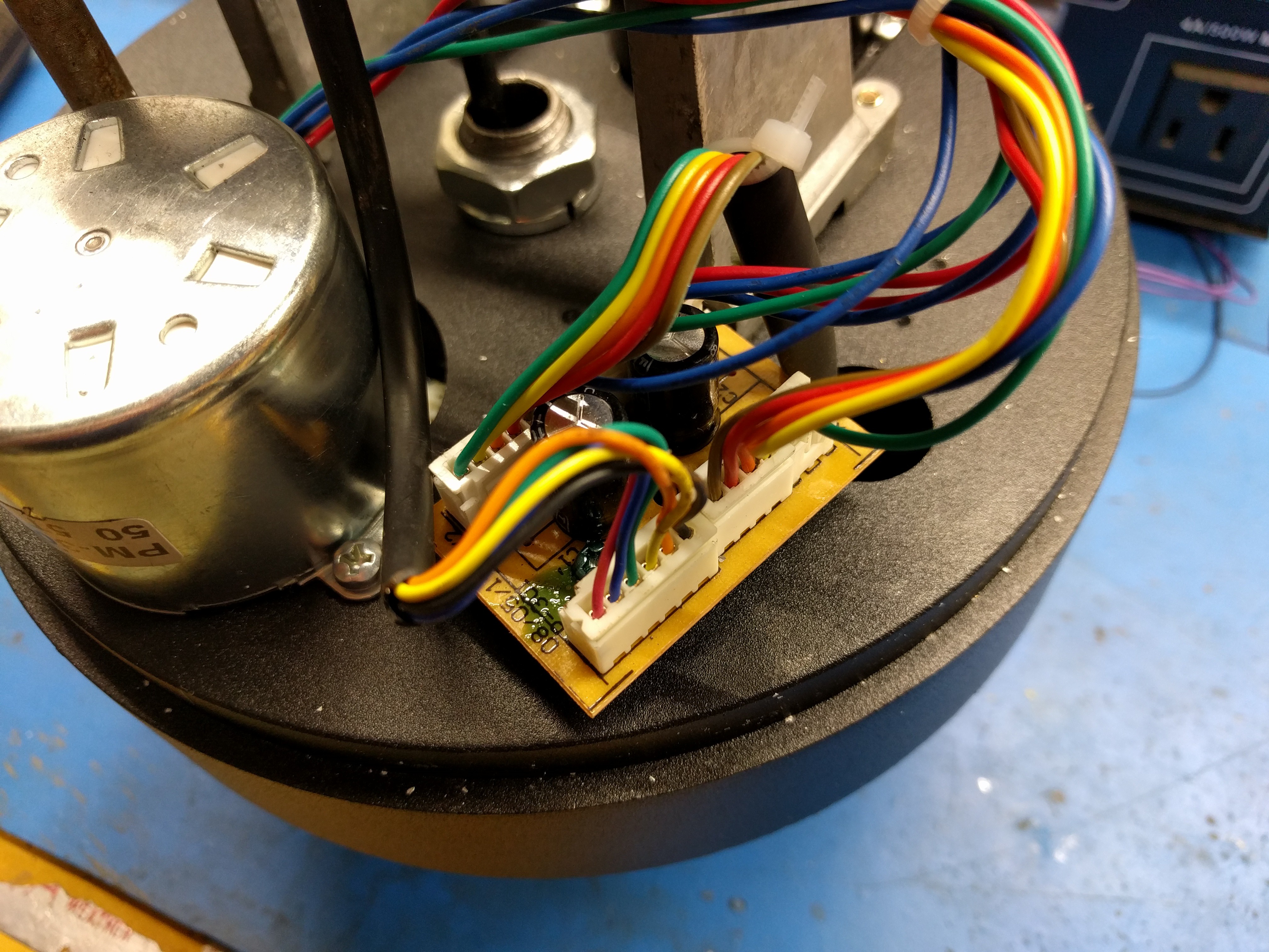
I was surprised how quiet the unit is! I was curious what kind of motors were used. I have been wondering if it will be necessary to add some position feedback to the unit or if I can just drive it for a certain amount of time and expect a certain amount of travel that is consistent. So I decided to dissect it and see what is inside. Here are some shots after disassembly:
![]()
![]()
![]()
![]()
![]()
I couldn't find any info about the motors on the internet unfortunately. I can tell that they have four leads. That, plus the PCB with 2 capacitors makes me think that these are Permanent Split Capacitor motors. Since this is an induction type motor, there is unfortunately always slippage so the motor speed will vary with load and is not fixed at line frequency.
I will have to see if this leads to problems where I will have to add position feedback or not. For now, I intend to just rely on the limit switches that are built in to the stage. I do not have direct access to these switches, but I intend to just move the pan and tilt in one direction for a while so both axes will be at their calibrated positions and then go from there based on timing. I'll have to see how quickly position will start to drift and if it's acceptable or if position feedback will have to be added.
PTSprinkler
Smart sprinkler on a Pan/Tilt mount to programmatically water the lawn with a fill pattern