 ElectroBoy
I have been working with energy metering ICs for a while now. After trying BL0937 which has a pretty straightforward control interface, today I finally got my hands on the BL0940. Both are similar, because they are single-phase energy metering IC but what surprise me the most is its feature set. Unlike the simpler BL0937 ICs in the BL series, the BL0940 gives you voltage, current, active power, energy accumulation, phase angle, power factor and temperature without the need of component calibration, and all data is accessible though UART or SPI.
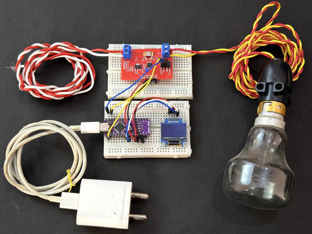
But for now this tutorial is focused on SPI communication mode. You just pull the SEL pin HIGH for SPI, and the IC switches its entire communication interface. I built a complete Arduino library around this IC with five ready-to-use examples. The total component cost is very low a 1 milliohm shunt resistor, a voltage divider network, and a few capacitors is all you need on the analog front end. This is a open source project you can access the design files through GITHUB, I have made a dedicated PCB from JLCPCB and tested it out with real time energy monitoring in my lab.
What Is BL0940?
The BL0940 is a single-phase energy metering IC, It has two sigma-delta ADCs for simultaneous voltage and current sampling, a digital multiplier for real-time active power computation, and an energy accumulator with pulse output. The IC operates from a 3.3V supply and uses an internal 1.218V reference voltage for all measurements. We can plug a load from 1W to 2500 watts in this with the PCB that I have designed. BL0940 has internal phase angle register with this register you can compute the phase difference between voltage and current, in order to get true power factor as cos(phi) without any extra signal processing. The BL0940 also has a built-in internal temperature sensor and supports an external NTC thermistor on the VT pin.
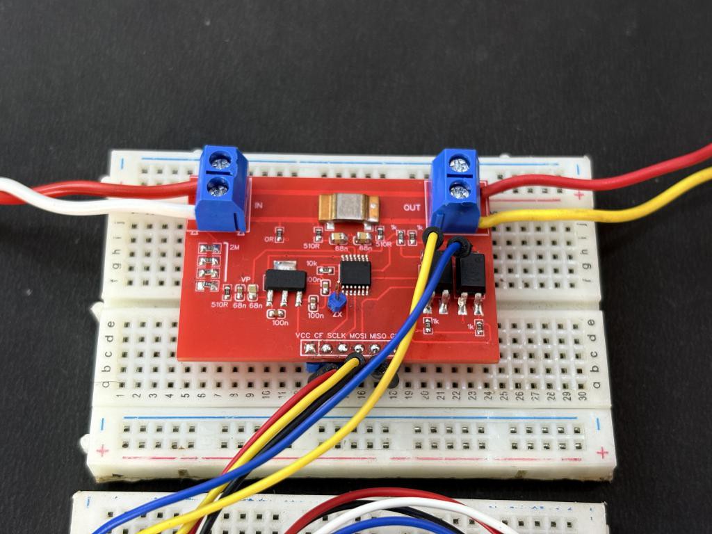
Here are the key specifications from the datasheet:
- Supply Voltage: 3.0V to 3.6V (typical 3.3V)
- Internal Reference: 1.218V (typ.)
- Differential input (IP/IN), max input +/-200 mV
- Differential input (VP/VN), max input +/-200 mV (after divider)
- UART at 4800 baud (fixed) or SPI up to 900 kHz
- Temperature Sensors: Internal (TPS1) + External NTC (TPS2), 10-bit ADC
- Anti-Creep register
- Energy Pulse Output
- Zero-Crossing Output
Components Required
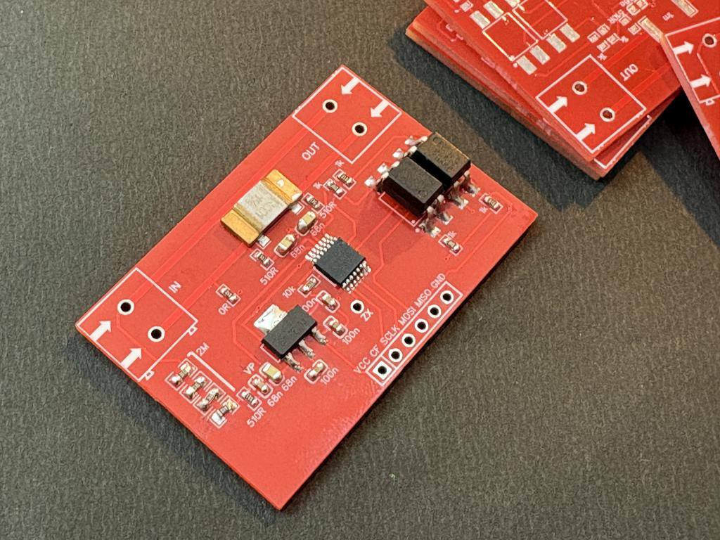
- BL0940 energy metering IC (SOP-14)
- Arduino Uno/Nano
- 1 milliohm (1 mOhm) shunt resistor
- 4 x 300K ohm resistors for the high side of the voltage divider (total 1.2 MOhm)
- 1 x 510 ohm resistor for low side of the voltage divider
- 2 x 2.2 uF capacitors for anti-aliasing filter on VP and IP channels
- 2 x 100 nF (0.1 uF) decoupling capacitors
- 1 x 10 uF electrolytic capacitor
- Custom PCB from JLCPCB
Circuit Diagram
I had followed the datasheet, and used the circuit as per the configuration in the documentation. The current sensing path uses a 1 milliohm shunt resistor connected between the IP1 and IN1 pins. At the maximum rated current, the voltage drop across this shunt stays well within the +/-200 mV. The 2.2 uF anti-aliasing capacitor are added across the IP/IN inputs to filter out high-frequency noise from the mains. This is important because the sigma-delta ADC inside the BL0940 can alias at high-frequency harmonics.
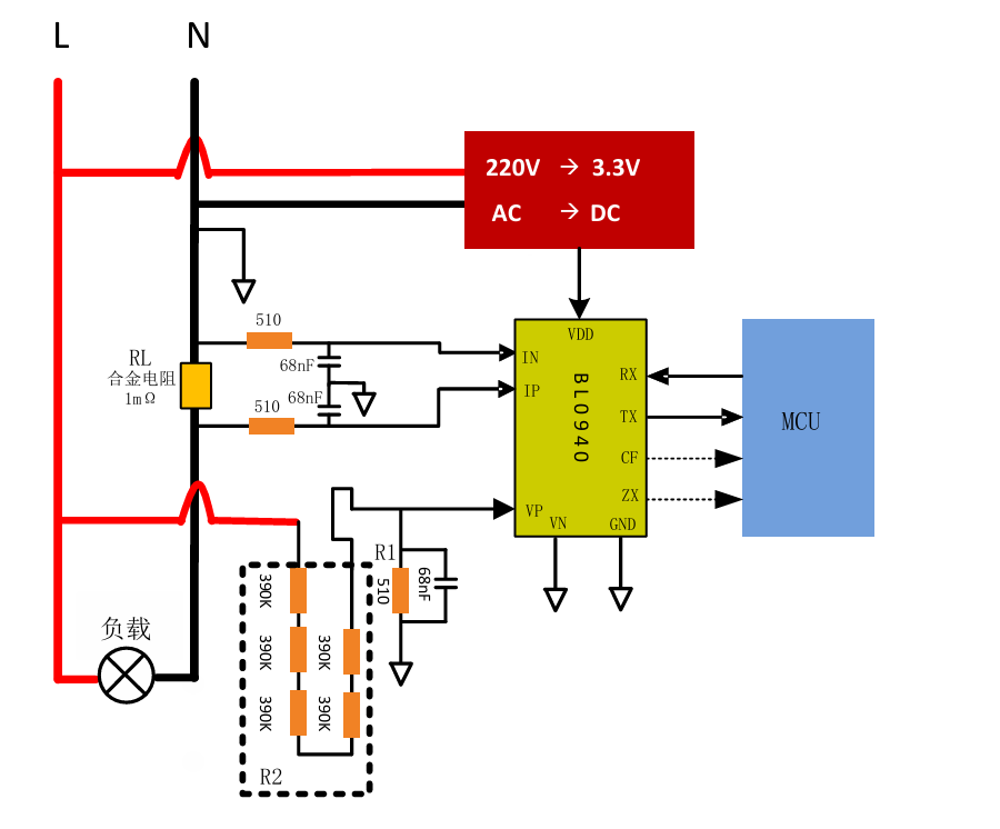
Four 300K ohm resistors in series (1.2 MOhm total) form the high side, and a 510 ohm resistor forms the low side. This gives a division ratio of approximately 2354:1, which scales 220V mains down to about 93 mV at the VP pin safely within the ADC input range. For power supply, the BL0940 runs on 3.3V. I have placed a 100 nF ceramic capacitor right next to the VDD pin for high-frequency decoupling, the power is given through the onboard LDO AMS1117 3.3V.
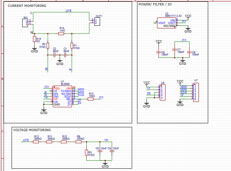
The CF pin outputs energy pulses and can be used for kWh counting or alarm output, while the ZX pin provides a zero-crossing signal synchronized to the mains frequency. Which are not used in this version of the tutorial. All readings are sent to the Serial Monitor, and the library handles all the register-level communication.
Understanding the Register Map
Understanding the register map is essential because the library is built entirely around reading these registers:
- I_FAST_RMS (0x00): Measures fast current RMS value (half/full cycle)
- I_WAVE (0x01): Stores instantaneous current waveform data
- V_WAVE (0x03): Stores instantaneous voltage waveform data
- I_RMS (0x04): Measures current RMS over a 400/800 ms window
- V_RMS (0x06): Measures voltage RMS over a 400/800 ms window
- WATT (0x08): Stores active power measurement
- CF_CNT (0x0A): Energy pulse counter register
- CORNER (0x0C): Measures phase angle between voltage and current
- TPS1 (0x0E): Internal temperature sensor reading
- TPS2 (0x0F): External temperature sensor (NTC) reading
Library Design and Conversion:
The BL0940 supports two communication modes, and understanding the protocol is important because the data byte order is different between UART and SPI, I am focusing on SPI because it is more stable and fast, in the library there you can find code for UART also, for the SPI Mode (SEL = HIGH). In SPI mode, the BL0940 uses Mode 1 (CPOL=0, CPHA=1), MSB first, with a maximum clock of 900 kHz. The frame structure is similar to UART but the byte order is reversed, MSB first in SPI mode. The library uses 500 kHz as the default SPI clock for reliable operation.
// SPI read: send CMD + ADDR, receive H, M, L, Checksum
SPI.transfer(BL0940_READ_CMD);   // 0x58
SPI.transfer(addr);
uint8_t b1 = SPI.transfer(0x00); // Data_H (MSB first in SPI!)
uint8_t b2 = SPI.transfer(0x00); // Data_M
uint8_t b3 = SPI.transfer(0x00); // Data_L
uint8_t rxCS = SPI.transfer(0x00);
Both modes use the same checksum formula: the bitwise NOT of the sum of all bytes except the checksum itself. I wrote this library to be as clean and straightforward as possible. Let me walk you through the key design decisions and functions.
// SPI mode -- csPin (-1 if not used), clock in Hz
BL0940 meter(-1, 500000);
Initialization and Verification: The `begin()` function initializes the communication interface and verifies that the BL0940 is responding, for that I have chosen the TPS1 (internal temperature) register for verification because it always returns a valid non-zero value as long as the chip is powered and communicating. If `begin()` returns false, you know immediately that something is wrong with your wiring or the SEL pin configuration.
Measurement Conversion: The raw register values from the BL0940 need to be converted to engineering units using calibration divisors. Here is how the voltage reading works internally:
float BL0940::getVoltage(void) {
uint32_t raw = readReg(BL0940_REG_V_RMS);
if (raw == BL0940_READ_ERROR) return -1.0f;
return (float)raw / _voltageDiv;
}
The `_voltageDiv` is a calibration constant that depends on your specific voltage divider values. The datasheet gives us the formula:
V_actual = raw  Vref  (R_high + R_low) / (79931  R_low)

For my circuit with 1.2 MOhm + 510 Ohm divider and Vref = 1.218V:

voltage_div = 79931  510 / (1.218  1200510) = 27878.5
Similar calibration divisors exist for current (default 266.0 for a 1 mOhm shunt) and power (default 1158.2). You can override these with `setVoltageDiv()`, `setCurrentDiv()`, and `setPowerDiv()`.
Calibration using Load:
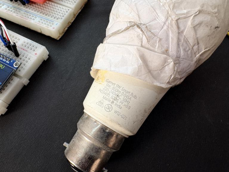
The SEL pin must be tied to VDD (3.3V) for SPI mode. Now use a 100W bulb, note down the socket voltage current and compute power manually using multimeter. Then feed the values inside the code like this:
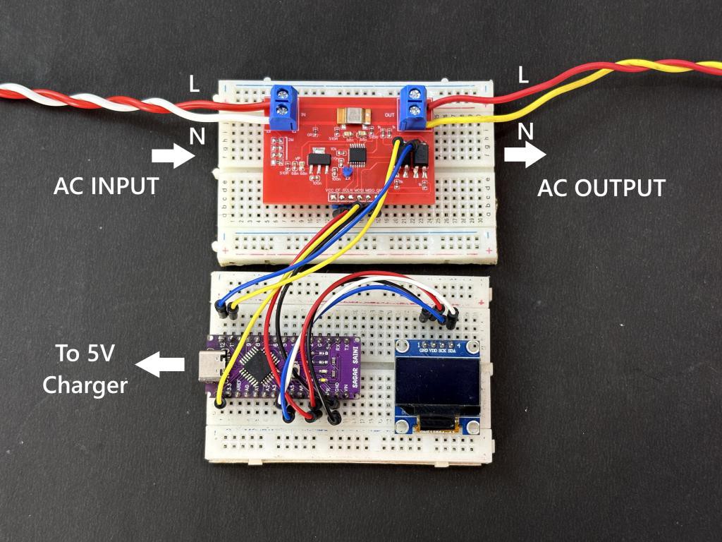
Make the onboard circuit as given here, you have to use the OLED, do not use laptop serial monitor when the IC is plugged in 220V. Laptop is only used to upload the program in the Arduino.
/**
 * BL0940 SPI Calibration + SSD1306 OLED
 *
 * Uses SPI mode exactly like the main example
 * and displays calibration divisors on OLED.
 *
 * Wiring:
 * --------------------------------
 * BL0940:
 *   SCLK   -> D13
 *   RX/SDI -> D11
 *   TX/SDO -> D12
 *   SEL    -> 3.3V
 *   VDD    -> 3.3V
 *   GND    -> GND
 *
 * OLED SSD1306:
 *   SDA -> A4
 *   SCL -> A5
 *   VCC -> 5V
 *   GND -> GND
 */

#include <SPI.h>
#include <Wire.h>
#include <BL0940.h>

#include <Adafruit_GFX.h>
#include <Adafruit_SSD1306.h>

// ---------------- OLED ----------------
#define SCREEN_WIDTH 128
#define SCREEN_HEIGHT 64
#define OLED_RESET    -1
#define SCREEN_ADDRESS 0x3C

Adafruit_SSD1306 display(
    SCREEN_WIDTH,
    SCREEN_HEIGHT,
    &Wire,
    OLED_RESET
);

// -------------- BL0940 SPI ----------------
// Same as main example
BL0940 meter(-1, 500000);

// ===== Reference Meter Values =====
const float ACTUAL_VOLTAGE = 249.0;
const float ACTUAL_CURRENT = 0.402;
const float ACTUAL_POWER   = 100.0;
// ===================================

void setup()
{
    Serial.begin(115200);

    // OLED Init
    if (!display.begin(SSD1306_SWITCHCAPVCC, SCREEN_ADDRESS)) {

        Serial.println("SSD1306 allocation failed");

        while (1);
    }

    display.clearDisplay();
    display.setTextColor(SSD1306_WHITE);

    display.setTextSize(1);
    display.setCursor(0, 0);
    display.println("BL0940 SPI");
    display.println("Calibration");
    display.println("Initializing...");
    display.display();

    // BL0940 Init (SPI)
    if (!meter.begin()) {

        Serial.println("BL0940 not detected!");

        display.clearDisplay();
        display.setCursor(0, 0);
        display.println("BL0940 ERROR!");
        display.println("Check SPI");
        display.println("SEL HIGH");
        display.display();

        while (1) {
            delay(1000);
        }
    }

    Serial.println("BL0940 initialized.");

    // Stabilization delay
    display.clearDisplay();
    display.setCursor(0, 0);
    display.println("Wait...");
    display.println("Stabilizing");
    display.display();

    delay(3000);

    // Read raw registers
    uint32_t raw_v = meter.readReg(BL0940_REG_V_RMS);
    uint32_t raw_i = meter.readReg(BL0940_REG_I_RMS);
    uint32_t raw_p = meter.readReg(BL0940_REG_WATT);

    // Calculate divisors
    float voltage_div = (float)raw_v / ACTUAL_VOLTAGE;
    float current_div = (float)raw_i / ACTUAL_CURRENT;
    float power_div   = (float)raw_p / ACTUAL_POWER;

    // Serial Output
    Serial.println();
    Serial.println("=== Calibration Divisors ===");

    Serial.print("meter.setVoltageDiv(");
    Serial.print(voltage_div, 1);
    Serial.println(");");

    Serial.print("meter.setCurrentDiv(");
    Serial.print(current_div, 1);
    Serial.println(");");

    Serial.print("meter.setPowerDiv(");
    Serial.print(power_div, 1);
    Serial.println(");");

    // OLED Output
    display.clearDisplay();

    display.setTextSize(2);

    display.setCursor(0, 0);
    display.println("Calibrate");

    display.setTextSize(1);
    display.setCursor(0, 20);
    display.print("VDiv:");
    display.println(voltage_div, 1);

    display.setCursor(0, 36);
    display.print("IDiv:");
    display.println(current_div, 1);

    display.setCursor(0, 52);
    display.print("PDiv:");
    display.println(power_div, 1);

    display.display();
}

void loop()
{
    // Nothing required
}
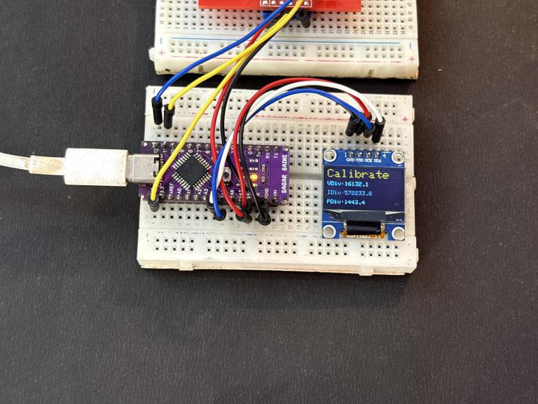
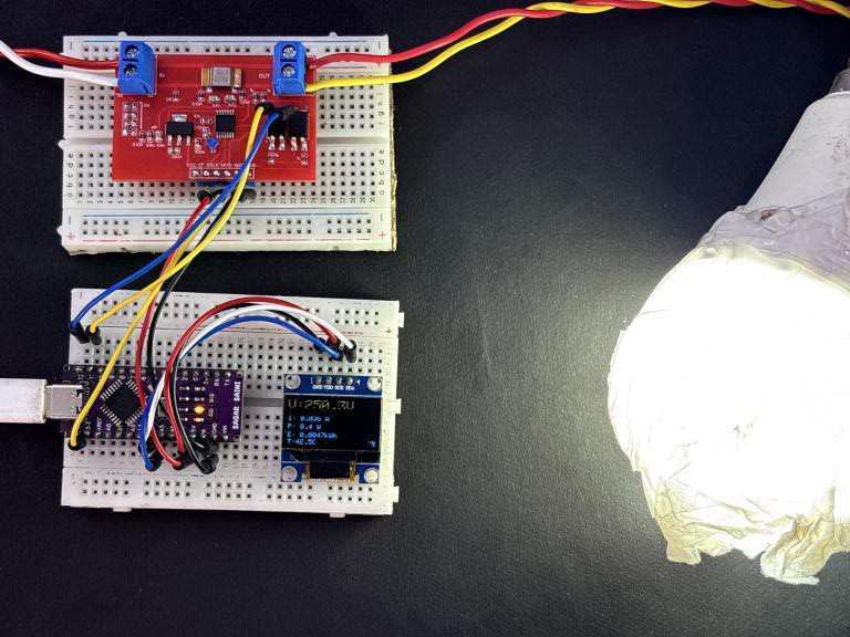
After upload connect the 5V power charger and load as given here, and note down the coefficients that are displayed on the OLED. Note them down and copy in the main working code for calibration.
Working Code:
Here is the main working code after uploading the calibration coefficients see how the reading changes.
#include <SPI.h>
#include <Wire.h>
#include <BL0940.h>
#include <Adafruit_GFX.h>
#include <Adafruit_SSD1306.h>

// OLED settings
#define SCREEN_WIDTH 128
#define SCREEN_HEIGHT 64
#define OLED_RESET    -1
#define SCREEN_ADDRESS 0x3C

Adafruit_SSD1306 display(
    SCREEN_WIDTH,
    SCREEN_HEIGHT,
    &Wire,
    OLED_RESET
);

// BL0940 SPI object
BL0940 meter(-1, 500000);

void setup()
{
    Serial.begin(115200);

    // OLED Init
    if (!display.begin(SSD1306_SWITCHCAPVCC, SCREEN_ADDRESS)) {

        Serial.println("SSD1306 allocation failed");

        while (1);
    }

    display.clearDisplay();
    display.setTextColor(SSD1306_WHITE);

    display.setTextSize(1);
    display.setCursor(0, 0);
    display.println("BL0940 Energy");
    display.println("Initializing...");
    display.display();

    // BL0940 Init
    if (!meter.begin()) {

        Serial.println("BL0940 not detected!");

        display.clearDisplay();
        display.setCursor(0, 0);
        display.println("BL0940 ERROR!");
        display.println("Check SPI");
        display.println("SEL HIGH");
        display.display();

        while (1) {
            delay(1000);
        }
    }

    // ===== Apply Calibration =====
    meter.setVoltageDiv(15988.6);
    meter.setCurrentDiv(568427.9);
    meter.setPowerDiv(1421.1);
    // =============================

    Serial.println("BL0940 initialized.");
    Serial.println("Calibration Applied.");

    display.clearDisplay();
    display.setCursor(0, 0);
    display.println("Calibration");
    display.println("Applied!");
    display.display();

    delay(1500);
}

void loop()
{
    float voltage = meter.getVoltage();
    float current = meter.getCurrent();
    float power   = meter.getPower();
    float energy  = meter.getEnergy();
    float temp    = meter.getInternalTemp();

    if (meter.lastReadOk()) {

        // Serial Output
        Serial.print("V=");
        Serial.print(voltage, 1);

        Serial.print("V  I=");
        Serial.print(current, 3);

        Serial.print("A  P=");
        Serial.print(power, 1);

        Serial.print("W  E=");
        Serial.print(energy, 4);

        Serial.print("kWh  T=");
        Serial.print(temp, 1);
        Serial.println("C");

        // OLED Display
        display.clearDisplay();

        // Large Voltage Display
        display.setTextSize(2);
        display.setCursor(0, 0);

        display.print("V:");
        display.print(voltage, 1);
        display.println("V");

        // Small Text
        display.setTextSize(1);

        display.setCursor(0, 22);
        display.print("I: ");
        display.print(current, 3);
        display.println(" A");

        display.setCursor(0, 34);
        display.print("P: ");
        display.print(power, 1);
        display.println(" W");

        display.setCursor(0, 46);
        display.print("E: ");
        display.print(energy, 4);
        display.println("kWh");

        display.setCursor(0, 56);
        display.print("T:");
        display.print(temp, 1);
        display.print("C");

        display.display();

    } else {

        Serial.println("Read error!");

        display.clearDisplay();
        display.setCursor(0, 0);
        display.println("Read Error!");
        display.display();
    }

    delay(1000);
}
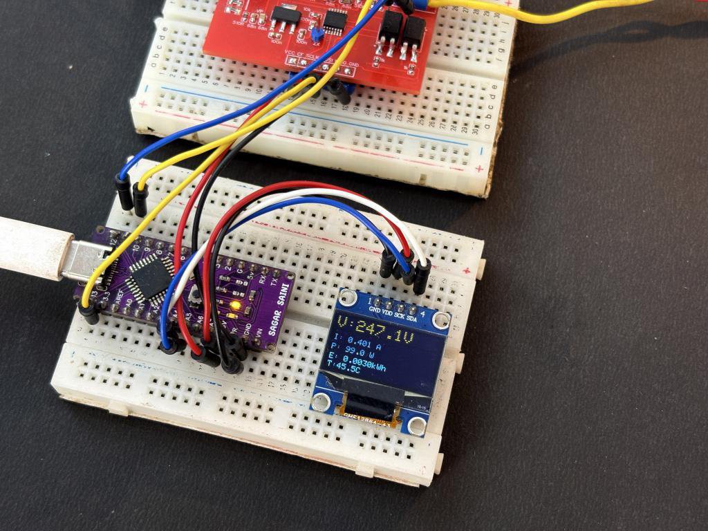
PCB Overview:
I have kept the PCB minimal and easy to plug, It is kind of breakout board which contain the main IC and supporting electronics, you can plug it with any microcontroller in order to make it working, For now I am using Arduino Nano.
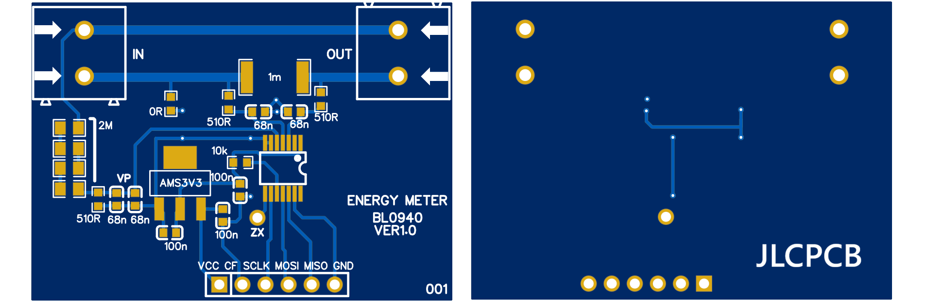
The PCB is simple yet it works, and I have tested it fully, keep in mind the LIVE and NEUTRAL connections, be careful when working with the AC voltage. You can download the files from here, with the working code. I have designed this in EasyEDA and fabricated using JLCPCB, I took me around an hour of soldering work to make it work in real life. If you want a proper soldered solution that works in the first go, I will recommend to go with JLCPCB PCB assembly services, you try them out in lowest prices from here.
Advanced Features:
Over-Current Detection (Fast RMS): The BL0940 has a dedicated fast RMS engine that can detect over-current conditions within a single half-cycle of the mains waveform. This is much faster than the normal RMS calculation, which uses a 400 or 800 ms window. You can set a threshold and use the CF/alarm pin to trigger a relay or protection circuit:
meter.setOverCurrentThreshold(threshold);
// threshold is compared against I_FAST_RMS23:9]
The I_FAST_RMSCTRL register also lets you choose between half-cycle and full-cycle refresh modes.
Anti-Creep Threshold: In real energy meters, there is always a tiny residual power reading even when no load is connected. This is called "creep" and it can cause your energy counter to slowly accumulate. The BL0940 has a WA_CREEP register where you can set a minimum power threshold. Any power reading below this threshold is treated as zero:
meter.setCreepThreshold(threshold);
// Power below this threshold is ignored
Outro:
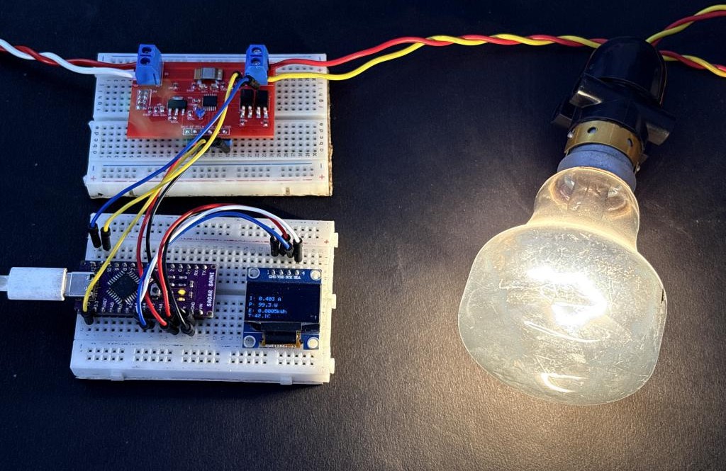
With all this we can say this is an amazing IC, you can download the main codes from GITHUB. Library works with any Arduino-compatible board that has a serial port or SPI. Whether you are building a commercial smart plug or just experimenting with energy measurement, this project gives you a solid foundation. Library works with any Arduino-compatible board that has a serial port or SPI. This IC find application in IoT related stuff out there, If you want to plan a power supply that deliver 5V directly from 220V see our tutorial on: Smallest 220V to 5V Supply for IOT applications. If you have any questions, suggestions, or want to share your own BL0940 build, please comment below. I would love to see what you make with it.