 ElectroBoy

I have been working with energy metering ICs for a while now. After trying BL0937 which has a pretty straightforward control interface, today I finally got my hands on the BL0940. Both are similar, because they are single-phase energy metering IC but what surprise me the most is its feature set. Unlike the simpler BL0937 ICs in the BL series, the BL0940 gives you voltage, current, active power, energy accumulation, phase angle, power factor and temperature without the need of component calibration, and all data is accessible though UART or SPI.
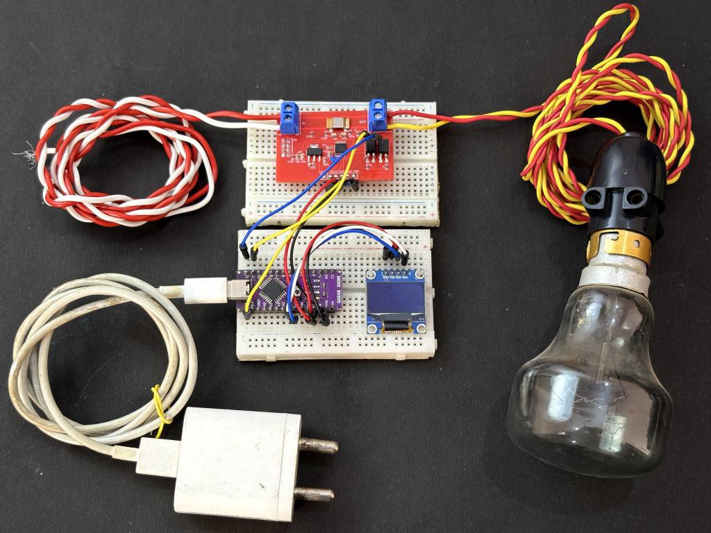
But for now this tutorial is focused on SPI communication mode. You just pull the SEL pin HIGH for SPI, and the IC switches its entire communication interface. I built a complete Arduino library around this IC with five ready-to-use examples. The total component cost is very low a 1 milliohm shunt resistor, a voltage divider network, and a few capacitors is all you need on the analog front end. This is a open source project you can access the design files through GITHUB, I have made a dedicated PCB from JLCPCB and tested it out with real time energy monitoring in my lab.
What Is BL0940?
The BL0940 is a single-phase energy metering IC, It has two sigma-delta ADCs for simultaneous voltage and current sampling, a digital multiplier for real-time active power computation, and an energy accumulator with pulse output. The IC operates from a 3.3V supply and uses an internal 1.218V reference voltage for all measurements. We can plug a load from 1W to 2500 watts in this with the PCB that I have designed. BL0940 has internal phase angle register with this register you can compute the phase difference between voltage and current, in order to get true power factor as cos(phi) without any extra signal processing. The BL0940 also has a built-in internal temperature sensor and supports an external NTC thermistor on the VT pin.
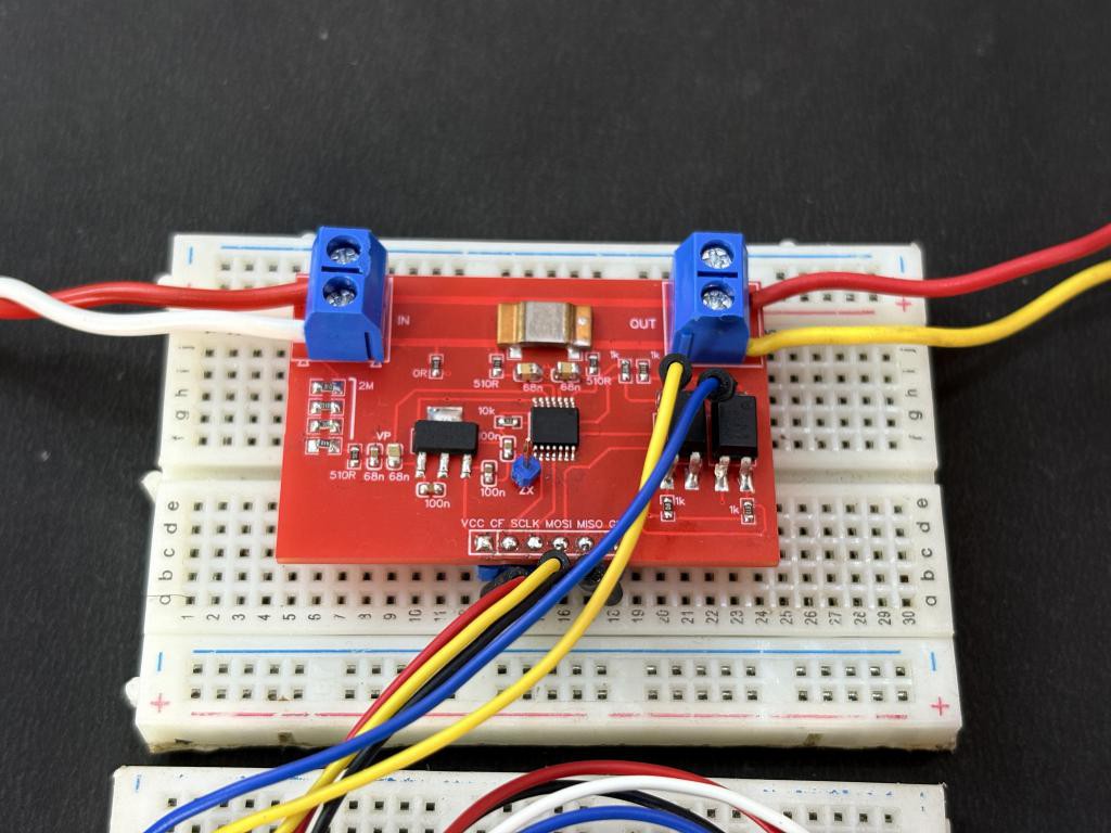
Here are the key specifications from the datasheet:
- Supply Voltage: 3.0V to 3.6V (typical 3.3V)
- Internal Reference: 1.218V (typ.)
- Differential input (IP/IN), max input +/-200 mV
- Differential input (VP/VN), max input +/-200 mV (after divider)
- UART at 4800 baud (fixed) or SPI up to 900 kHz
- Temperature Sensors: Internal (TPS1) + External NTC (TPS2), 10-bit ADC
- Anti-Creep register
- Energy Pulse Output
- Zero-Crossing Output
Components Required
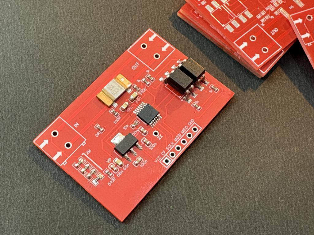
- BL0940 energy metering IC (SOP-14)
- Arduino Uno/Nano
- 1 milliohm (1 mOhm) shunt resistor
- 4 x 300K ohm resistors for the high side of the voltage divider (total 1.2 MOhm)
- 1 x 510 ohm resistor for low side of the voltage divider
- 2 x 2.2 uF capacitors for anti-aliasing filter on VP and IP channels
- 2 x 100 nF (0.1 uF) decoupling capacitors
- 1 x 10 uF electrolytic capacitor
- Custom PCB from JLCPCB
Circuit Diagram
I had followed the datasheet, and used the circuit as per the configuration in the documentation. The current sensing path uses a 1 milliohm shunt resistor connected between the IP1 and IN1 pins. At the maximum rated current, the voltage drop across this shunt stays well within the +/-200 mV. The 2.2 uF anti-aliasing capacitor are added across the IP/IN inputs to filter out high-frequency noise from the mains. This is important because the sigma-delta ADC inside the BL0940 can alias at high-frequency harmonics.
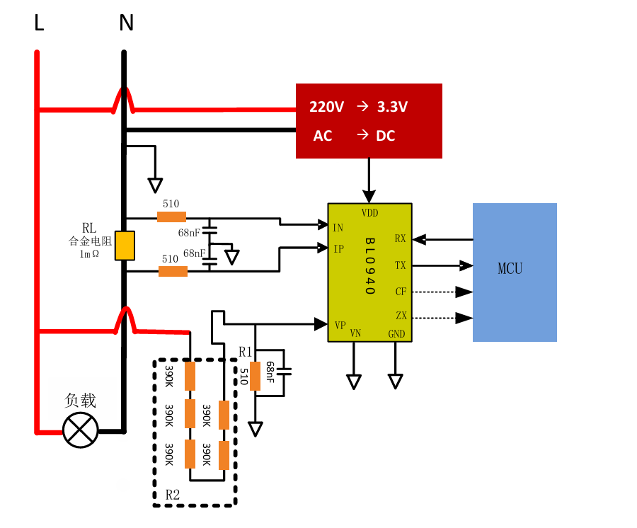
Four 300K ohm resistors in series (1.2 MOhm total) form the high side, and a 510 ohm resistor forms the low side. This gives a division ratio of approximately 2354:1, which scales 220V mains down to about 93 mV at the VP pin safely within the ADC input range. For power supply, the BL0940 runs on 3.3V. I have placed a 100 nF ceramic capacitor right next to the VDD pin for high-frequency decoupling, the power is given through the onboard LDO AMS1117 3.3V.
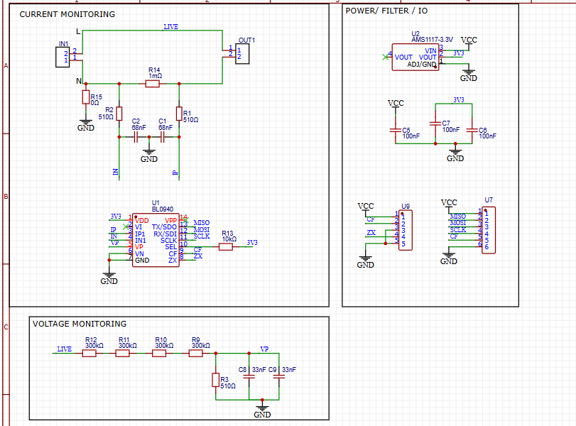
The CF pin outputs energy pulses and can be used for kWh counting or alarm output, while the ZX pin provides a zero-crossing signal synchronized to the mains frequency. Which are not used in this version of the tutorial. All readings are sent to the Serial Monitor,...
Read more »
 Radu Motisan
 Ghani Lawal

 Jan Waclawek
 Sagar 001