The plan is to design and build a digital bench power supply. As the starting point we have the following:
- a project metallic enclosure from an old ATX supply
- a microcontroller, the choice is Atmega8 (or for extended functionality, such as Bluetooth/HC-05, we'd use the Atmega168). This will be the central processing unit for the entire device.
- a lcd , to display all parameters, most likely a HD44780, either a 2x16 or a 4x20 one.
- a 250W transformer, and a 24VAC secondary with a center tap at 12VAC. Maximum current is 10amps.
- 4 buttons, to set voltage up/down and current up/down
- a little self oscillating buzzer to sound the alarm when needed (eg. shortcircuit).
Milestones to implement:
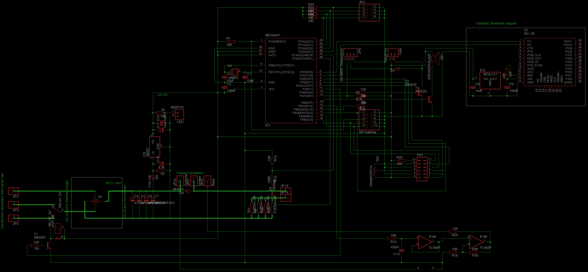
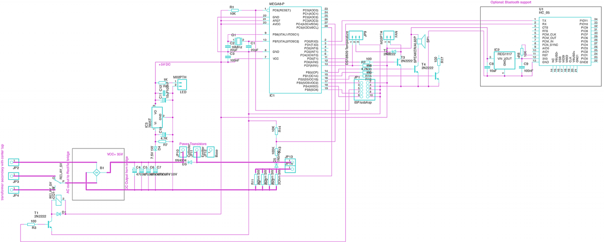
- the microcontroller is to simplify all hardware design, moving the complexity in the software. This includes driving the LCD, reading the input buttons, measuring the output voltage through a resistive voltage divider connected to an ADC port. Use the measured voltage to display it on screen, but also for the output control block.
- to support a maximum voltage of 24x1.414 ~= 34Volts, let's make that a round number 35V.
- output provided through low resistance high power shunt resistors (several connected in parallel to meet the requirements). Using the voltage drop on these resistors, we can calculate the current flowing through them which will be the current output. We use this value for the output control block, to display the current consumption on screen , and for short circuit protection. Critical states or shortcircuit are to be signalled via the buzzer as well.
- when selected output voltage is 12V or bigger, we use a relay automatically to switch from the center tap to full secondary. And the vice-versa, in order to optimise the power dissipated on the transistors.
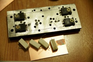
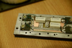
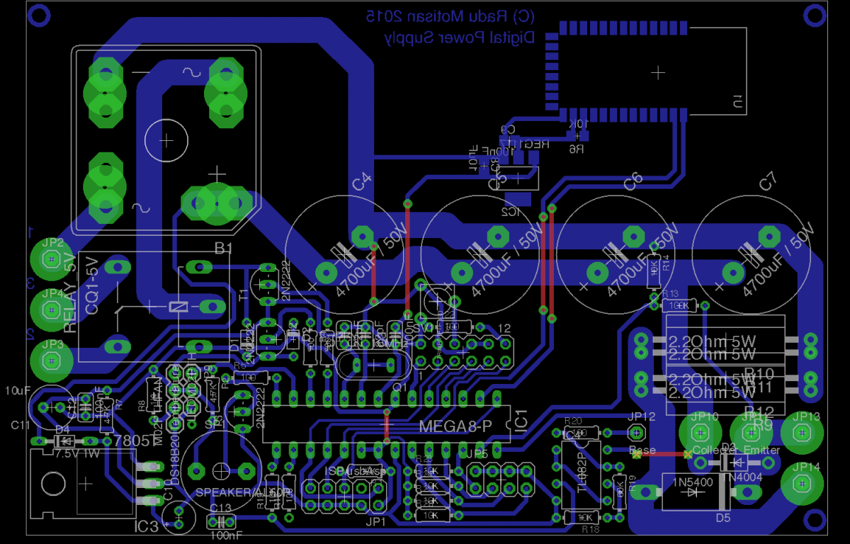
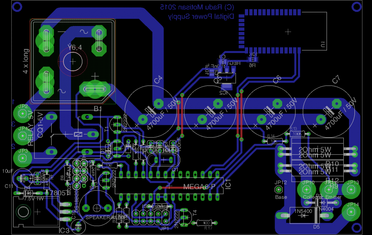
- output controlled with 4xTIP3055 power transistors connected in parallel on a heatsink with equalising resistors on the emitters.
- temperature sensor DS18B20 connected on the heatsink to start a fan automatically and with further increasing heating to reduce power to prevent supply damage. Temperature critical events will trigger the buzzer alarm as well.
- power transistors are to be controlled via a DAC module built either with a R-2R network or a PWM+low pass filter and an amplifier.
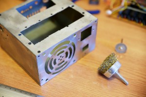 | 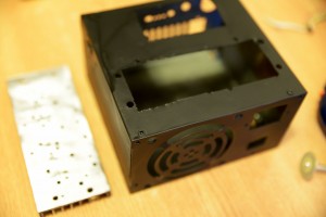 | 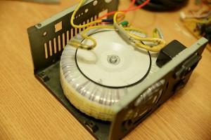 |
Here are the power transistors mounted on the heatsink:
 |  |
Things to decide / solve:
- the type of DAC to use: either the R/2R or the PWM+Low pass filter. I already did some tests with a Serial Digital to analog converter, presented here.
- choose the type of display to use, making sure it also fits the case
- choose a voltage amplifier , needed to boost the DAC output from 0..5V to 0..30V needed to command the base of the power transistors. I can either build one using transistors, either use an Op-amp.
- I could use an LM358, half with the DAC Low pass filter, and half as an amplifier
That's it for now , feel free to comment or post suggestions.
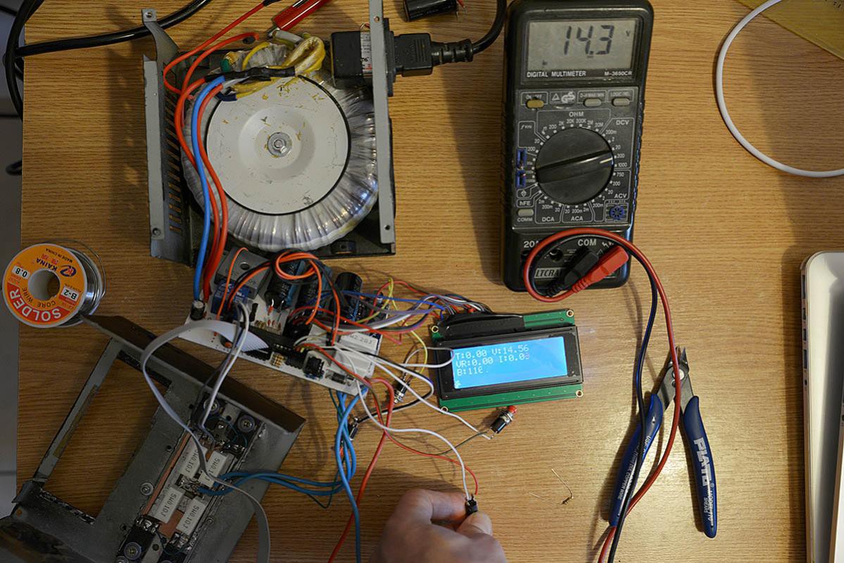
Edit: the supply has been completed, it works perfectly, and the source code is available on my blog: http://www.pocketmagic.net/digital-bench-power-supply/ . Checkout the log entries for an exciting story from design to completion.
Here is a presentation video to iterate some the functions: https://youtu.be/LduksHuTuo4
 Radu Motisan



 BleakyTex
 Kuba Sunderland-Ober
 Marc-O.
 jbb
jbb