 jbb
jbbHow can we sense currents?
There are 2 practical methods: shunt resistors and magnetic methods.
Shunt resistors are OK for low currents (10A or less) but do not provide isolation between your control circuit and power circuit (not so good for 400 V AC).
----
Magnetic methods can be scaled up to ferociously large currents (100 000 A +) and provide electrical isolation between the primary current (which you want to measure) and the secondary. Additionally, you can set a turns ratio (or equivalent) so that you output only a fraction of the primary current.
----
Various magnetic methods exist, most notably the Hall Effect sensor. These sensors produce an output voltage proportional to the applied magnetic field, so all you have to do is cut a ferrite ring in half, stick in a Hall effect sensor, and you're done, right?
Yes and no; cutting ferrite is seriously difficult as it tends to shatter. (My colleagure had some success with commercial water jet cutting, but he broke a lot of ferrite first!) Additionally, Hall Effect sensors are not super-accurate. Finally, you can just buy one from DigiKey / Mouser / Farnell etc. Where's the fun in that?
---
Enter the fluxgate. This is a magnetic field sensor which relies on <i>deliberately</i> saturating a ferrite (or other material) core. This is attractive because it means no ferrite cutting is required!
The first part of the project will consist of some explanation and experimentation with a single-core fluxgate. Things will get fancier from there...
I intend to deisgn and build a DCCT using SPICE simulations, repeatable measurements, PCB design and (somewhat) hacker friendly components. At present, I am thinking about a unit with 25A input / 1A output, and a maximum uncertainty of around 100 mA (0.4%).


 We now have an extra degree of freedom to play with: the current through the feedback windings If. With a bit of closed loop control, we can adjust If such that:
 We see that:
 Well, after a few ms of transient behaviour at startup, we do get a sinusoidal current out. However, we have quite a bit of phase shift (power measurements using this would be useless!). In a future post we will talk about bandwidth extension with a third ferrite core functioning as a current transformer.
 But we can compensate for it. We can do this by adding an opposing EMF to the circuit. A good way to do this is to add a second fluxgate with opposite 'polarity' to the first as shown:
 We now have a vastly reduced Ep term - theoretically zero (we will have a look at component tolerances later). Also, we now have the opportunity to measure the difference between Vm1 and Vm2, which we see is (in principle) zero Volts at zero primary current:
 And if we have a 1A primary current Ip, we get some nonzero quantites: the voltage between Vm1 and Vm2 is nonzero and Ep is nonzero.
 If we sweep Ip over a -3A to +3A range (this is the X axis), and look at the average of Vx (i.e. output of a low pass filter) and the RMS value of Ep, things look pretty good:
 Our current to voltage gain has doubled, and Ep is vastly reduced compared to the original 320 mV RMS. In fact, it should go to zero when Ip = 0 (note that component tolerances are not yet considered). So, we have gotten both more output signal and less voltage injection into the primary circuit, which is most welcome.
 Oh ****. Our sensor is nice and linear in the -3A to +3A range, but all kinds of nonlinear outside that (not sure what the glitch around +12A is, but I don't like it). This is not going to work as desired.
 V2 provides the excitation square wave.
 By adding some .measure commands to the Spice file, we can plot the average (i.e. DC component) of Vx against the applied Ip. This averaging can be implemented using a simple low pass filter. We are now getting something like 1 V / A gain - excellent.
 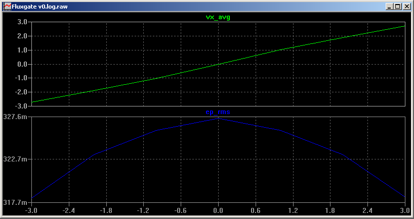 Next time we will look at a double core fluxgate to show how we can reduce Ep significantly.

 Bud Bennett
 Gangwa Labs
 Paul Andrews
 Jakob Wulfkind
Which Current Transducers is better to use depends in most cases from location, accuracy, of value of course. For 10A if You get shunt resistors 250 mOhm it generate heat around 0.25W. We used in a lot of cases IC from analogue device AD7400. It has digital insulated (~3kV) output. For some high voltage place we used Li-ion battery preliminary charged as sorce of energy of IC. The battery activates with signal aplied from fiber when measurements started to save charge of battery. The output of AD7400 - digital stream also insulated by fiber. I found good idea here from Mark (thank You) translating energy to high voltage places trough fiber. We produced a lot such board for research.