Close
0%
0%

DIY XBOX Controller

Made an XBOX controller from scratch using an ESP32C6 dev kit and custom 3D printed parts.

Similar projects worth following
0 followers
Greetings everyone, and welcome back. Here's something fun and custom.

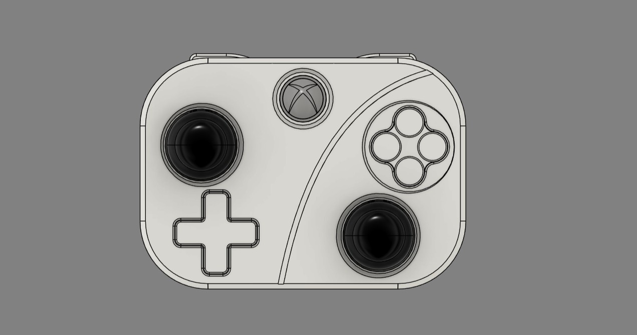
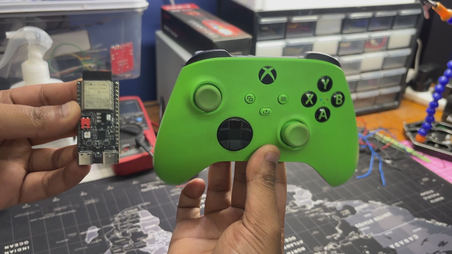
This is my version of an Xbox controller, which I built from scratch. It features an ESP32-C6 DevKit as the main MCU, paired with custom button boards, analog joysticks, and a custom-designed body to create a DIY Xbox wireless controller.

Using this controller is just like using any Xbox controller; we simply pair it with Bluetooth, open Steam, assign the button mapping, and play games with it.

For the demo, I tried playing Broforce and Fallout: New Vegas, and both of them worked well.

VIDEO

DESIGN

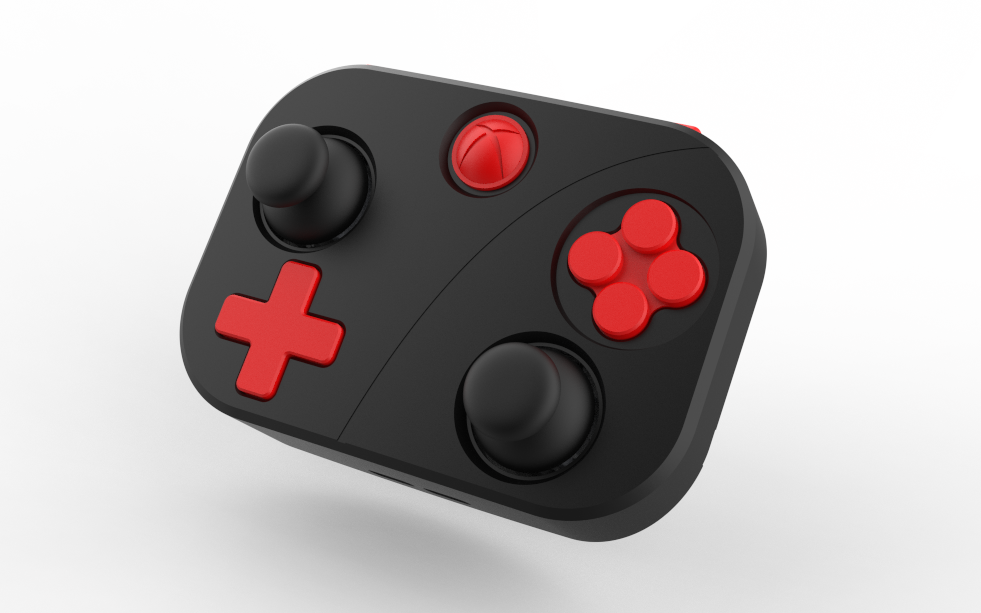
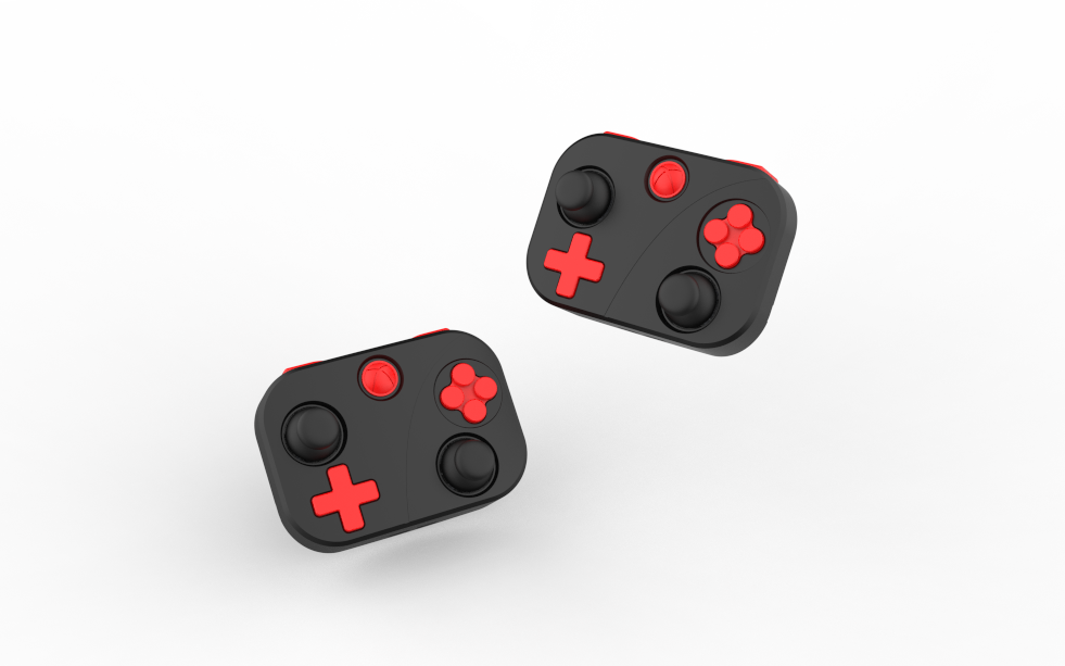
For the design of our controller, I wanted something simple that follows the Xbox controller button layout. I kept the button layout mostly the same, but changed the overall shape from a traditional controller design to a rounded cuboid shape with a curved back. The design is minimal, and for aesthetics, I planned to print the parts in two colors.

The entire design was created in Autodesk Fusion 360.

PARTS
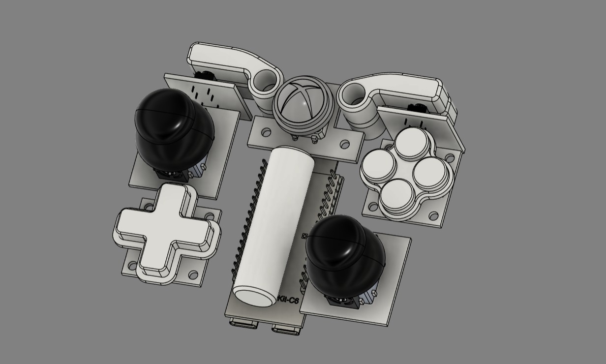
We began the design process by arranging all the hardware, such as the ESP32 board, analog sticks, switch PCBs, and lithium cell, in a layout similar to a regular Xbox controller. The button and joystick placement closely followed the Xbox controller layout, while the rest of the components were positioned wherever they fit best inside the design.

Based on this arrangement, the outer shell was designed around the components.

XBOX BUTTON SUDO PCB
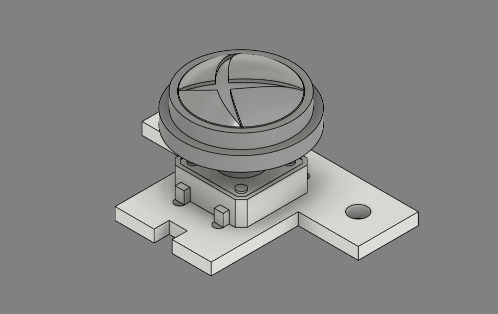
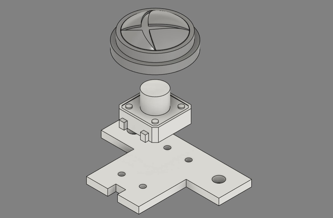
Now here’s a clever hack: did you know you can 3D print your own PCB? Well, not a complete PCB, but a board that can hold through-hole components in place. That’s exactly how I modeled the Xbox button PCB.

For this, I placed a 12×12 push button onto the design and added four mounting holes for the switch leads, along with two additional holes for mounting the board to the controller body.

The idea here is to print this board using regular PLA, place the switch onto it, and let the switch leads hold everything in place. Then, during wiring, we directly solder wires to the leads of the switch. This “PCB” only acts as a holder that keeps the switch securely positioned.

3D PRINTED PARTS
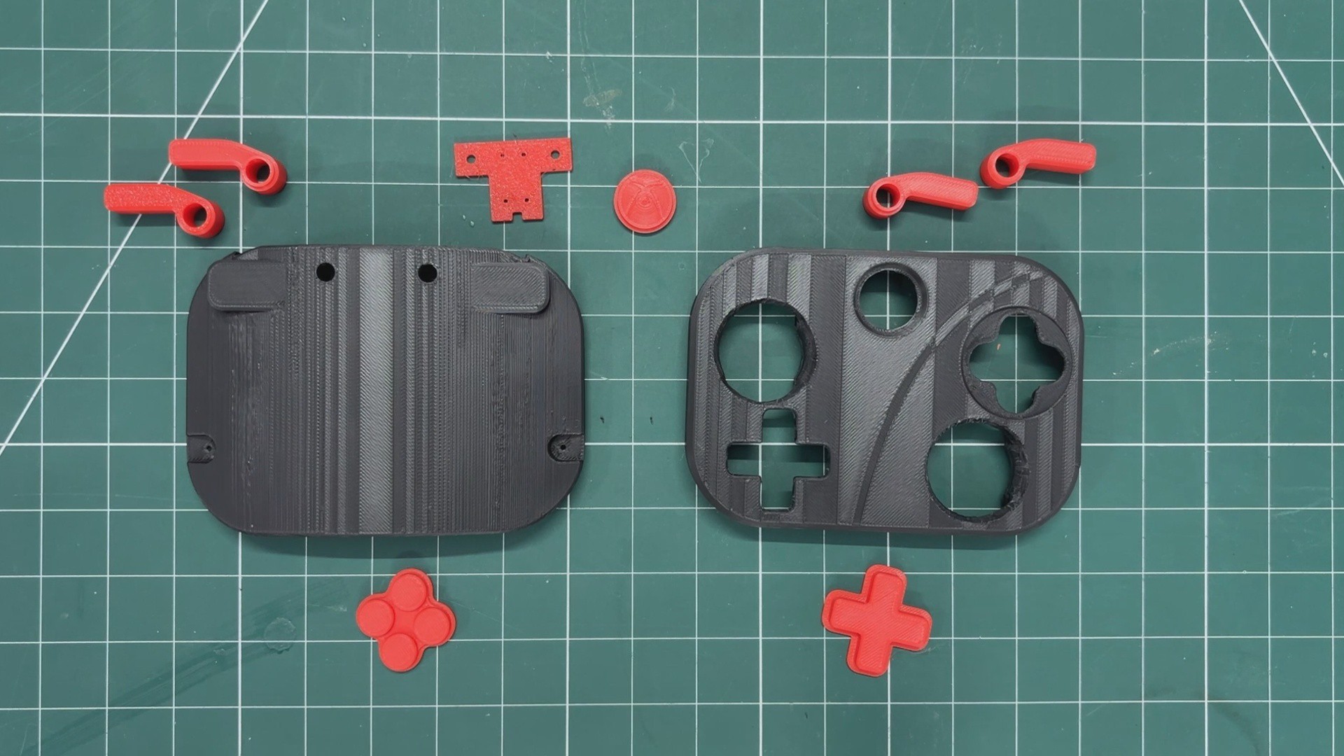
The front and back body parts were printed in black PLA, while all the buttons were printed in red PLA to create a dual-tone red-and-black color effect.

Here, we used HYPE PLA red and black filament for all the prints. All parts were printed at a 0.2mm layer height using a 0.4mm nozzle with 15% infill.

HARDWARE
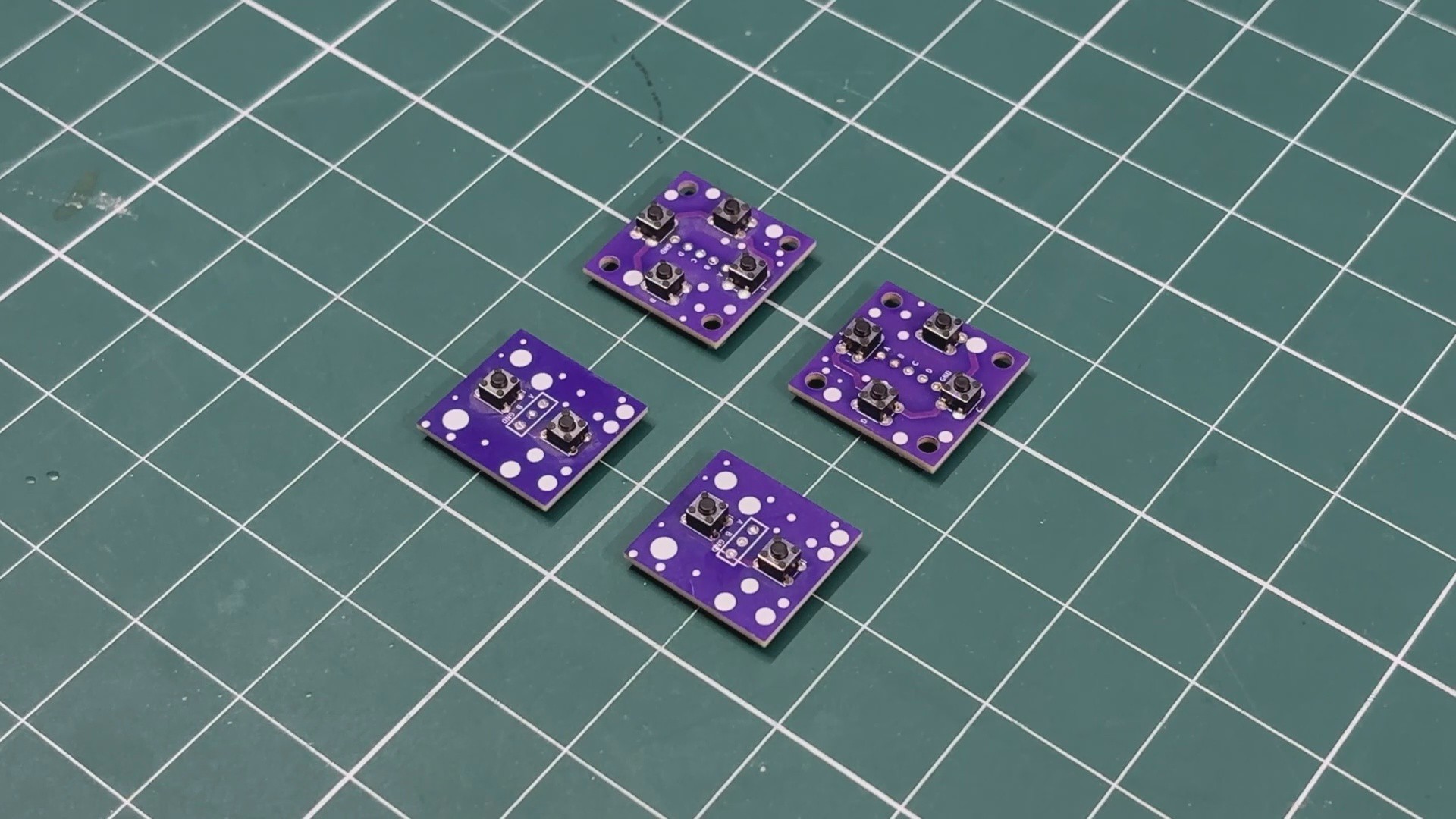
The hardware used in this project was fairly simple. We used an ESP32-C6 DevKit as the main controller, which provides plenty of GPIO pins, most of which are utilized in this build.

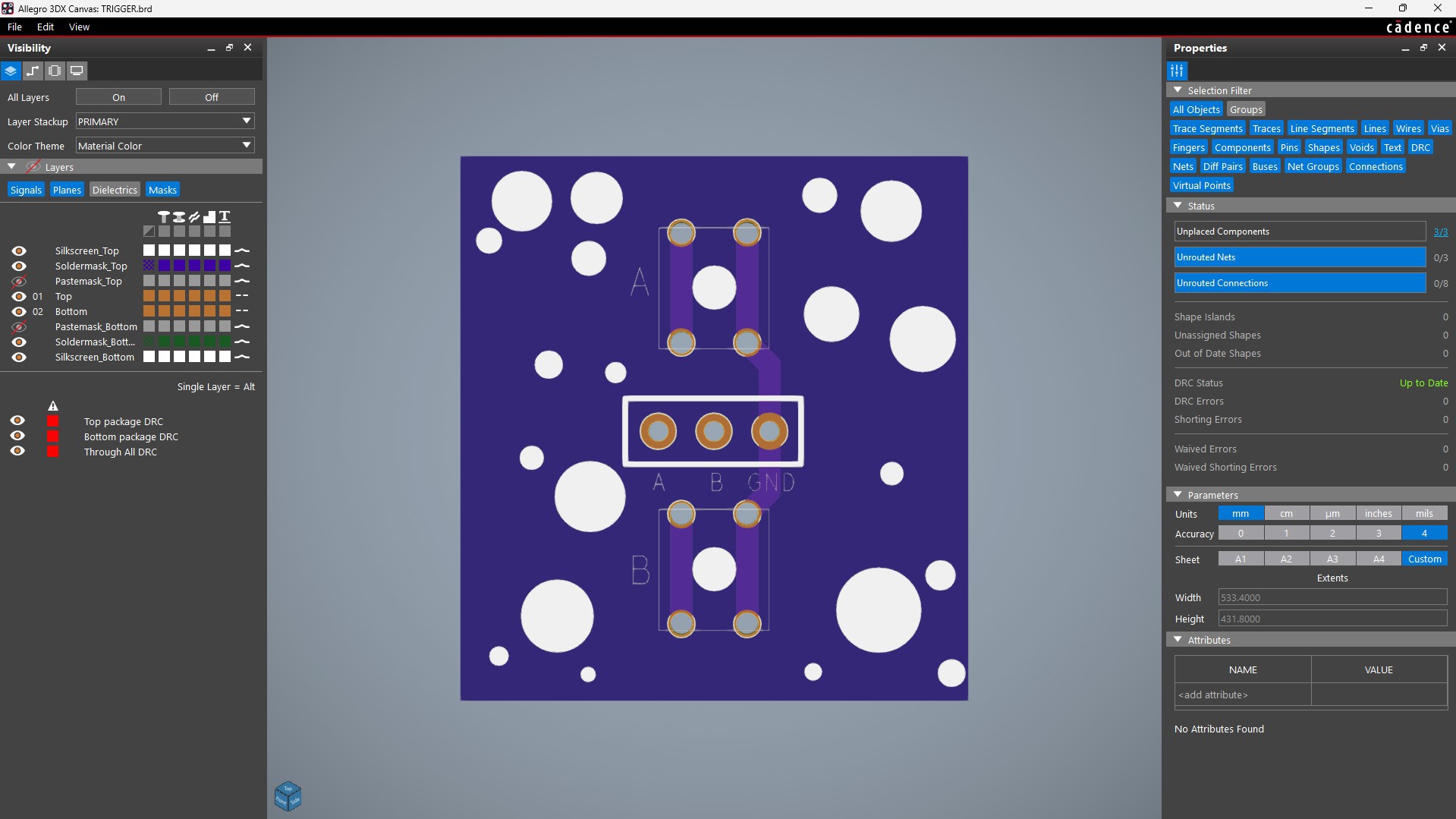
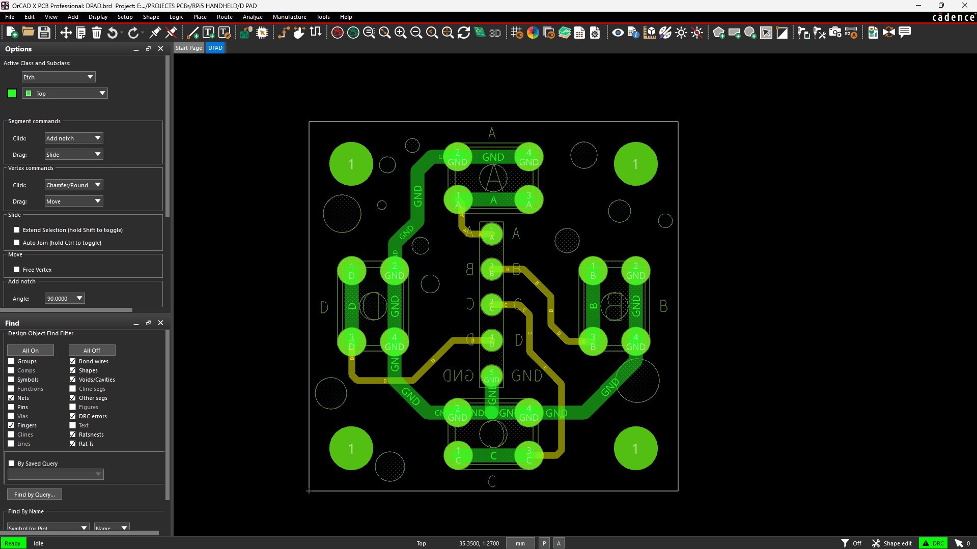
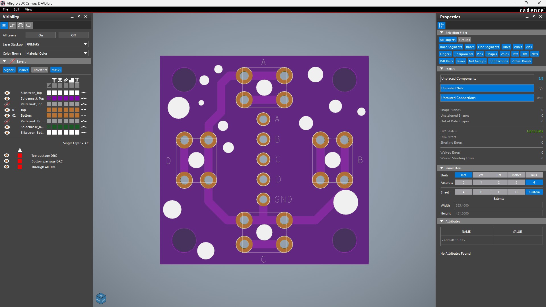
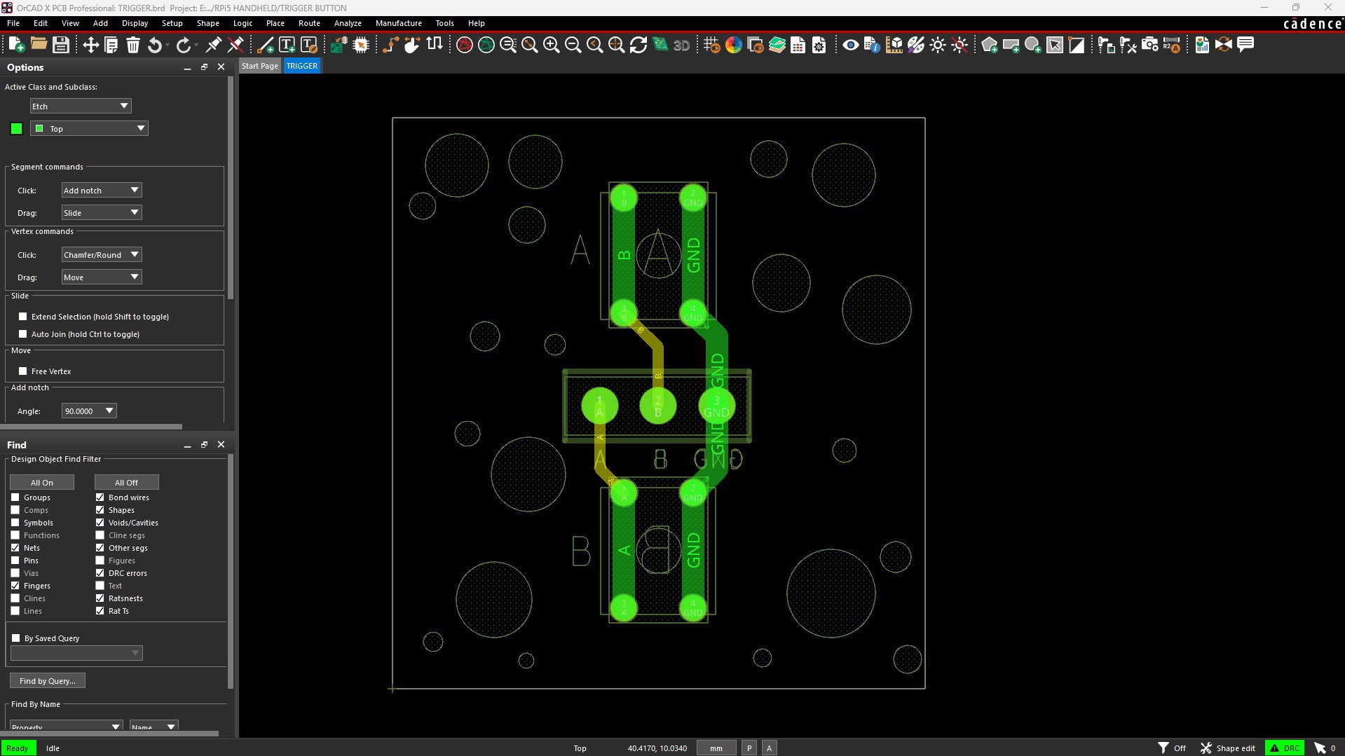
We also prepared custom D-pad and trigger button PCBs, which are used as button input boards.

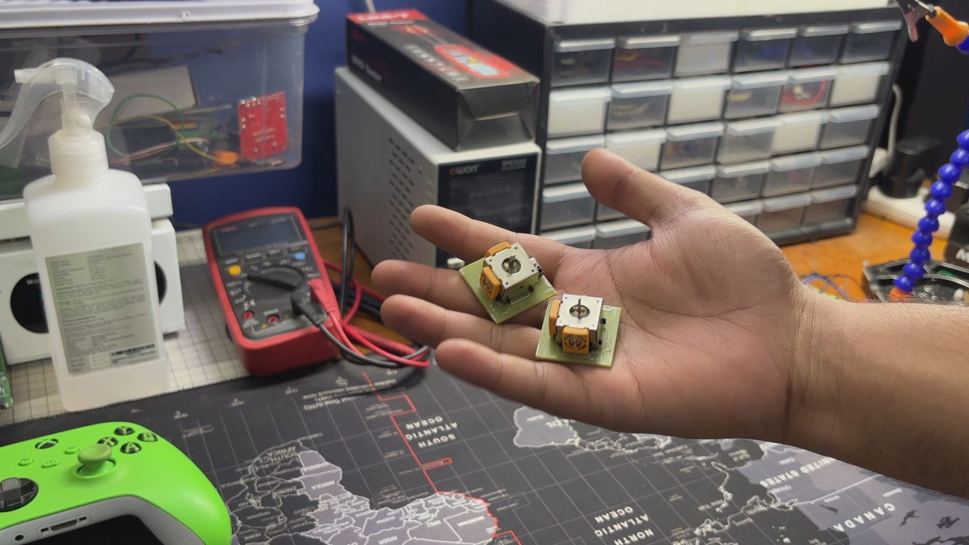
For the analog controls, we used generic analog joysticks that I got from Amazon. These are used as the left and right analog sticks for the controller.

PCB SWITCH BOARD
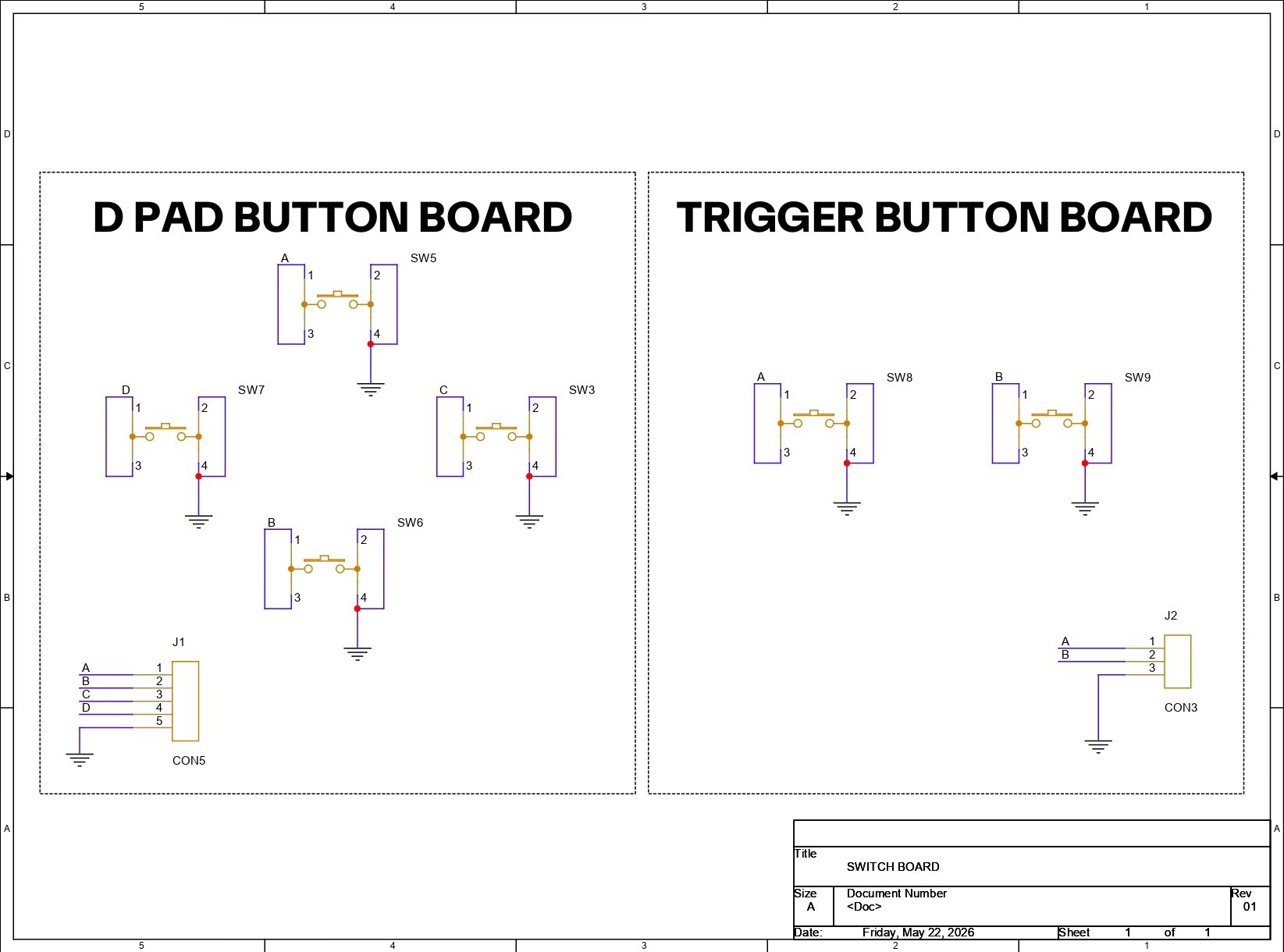
For the PCB design of this project, I’m using two button boards that I designed specifically for projects like this, where I need to add button functionality. The idea is simple: place multiple buttons on a PCB, connect one side of all the buttons to GND, and route the other side to a connector that can be interfaced with a microcontroller for button input.

These boards are mainly intended for proof-of-concept builds like this one. The board layout, outline, and push-button positions were all designed by following the CAD file dimensions of both switch boards.

PCBWAY SERVICE
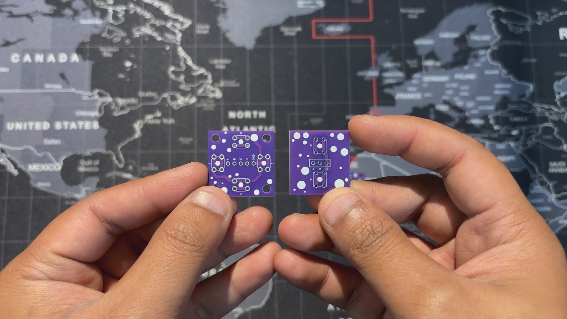
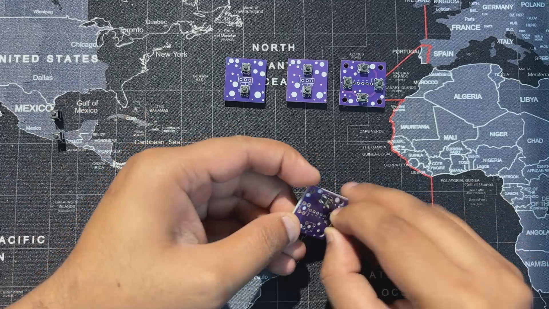
After finalizing the design, I generated the PCB Gerber files and sent them to PCBWay for fabrication. I chose a purple PCB with a white solder mask for both the trigger and D-pad PCBs.

The quality turned out to be excellent with a clean finish and sharp silkscreen, and everything matched the design perfectly.

Over the past ten years, PCBWay has built a strong reputation for providing reliable PCB manufacturing and assembly services, becoming a go-to choice for engineers and makers worldwide.

Honestly, if you’re making custom PCBs and not checking out PCBWay, you’re just making things harder for yourself. They also offer CNC machining and 3D printing services.
CONTROLLER.step

step - 14.11 MB - 05/29/2026 at 04:49

Download

TOP.stl

Standard Tesselated Geometry - 1.92 MB - 05/29/2026 at 04:49

Download

xboxbuttonassembly.stl

Standard Tesselated Geometry - 688.17 kB - 05/29/2026 at 04:49

Download

SW3.stl

Standard Tesselated Geometry - 118.34 kB - 05/29/2026 at 04:49

Download

XYAB.stl

Standard Tesselated Geometry - 248.32 kB - 05/29/2026 at 04:49

Download

View all 11 files

  • 1
    PCB ASSEMBLY

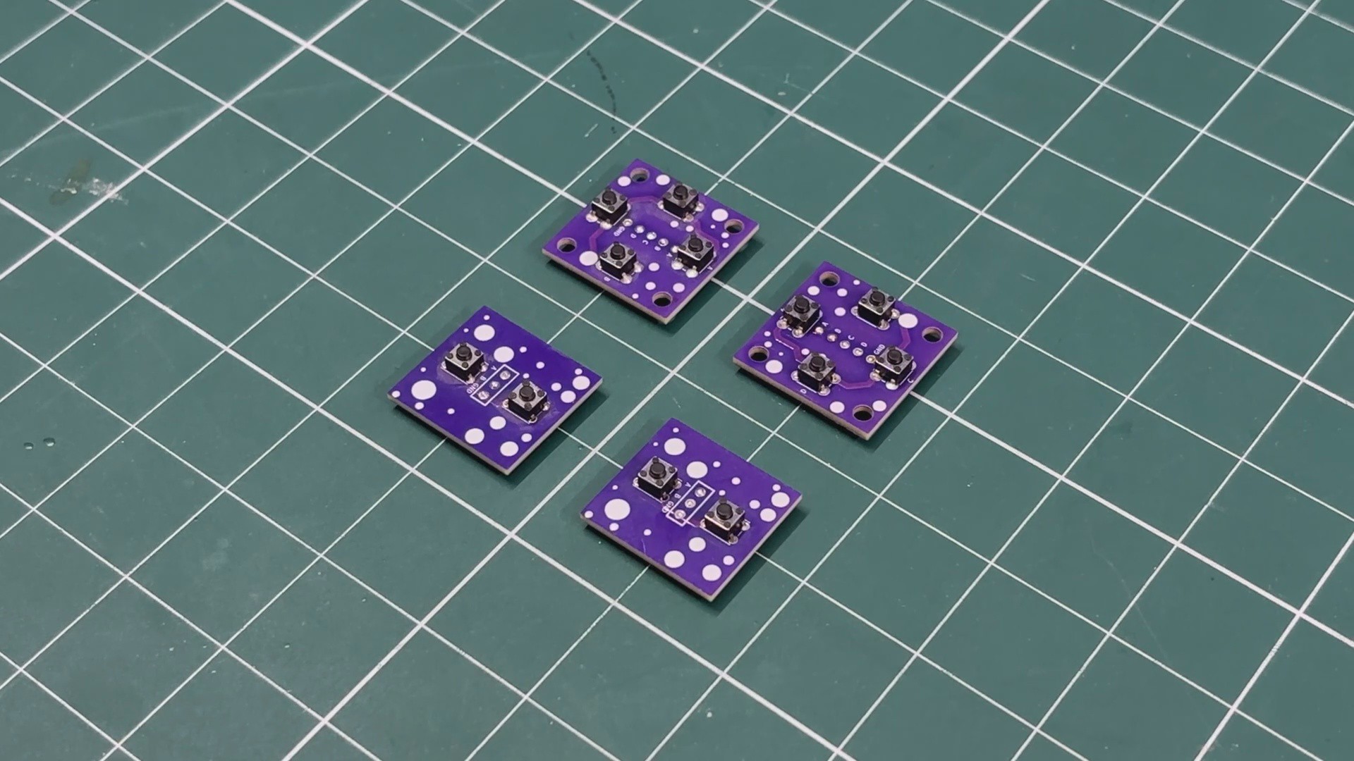
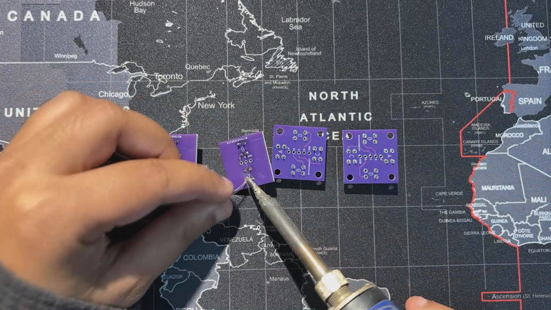
    The assembly process for these two button boards was also simple. The only component required was a 4×4 push switch. For our build, we needed two four-button boards and two double-button boards, making a total of 12 buttons. Each button was placed one by one into its designated position on all four boards.

    After that, each board was flipped over, and we used a soldering iron to permanently secure all the switches in place, completing the button board assembly process.

  • 2
    POWER SOURCE ASSEMBLY

    For the power source of our controller, we wanted to use something smaller than regular 18650 cells. Using a LiPo battery was one option, but they don’t have enough capacity to power our device for hours of gameplay.

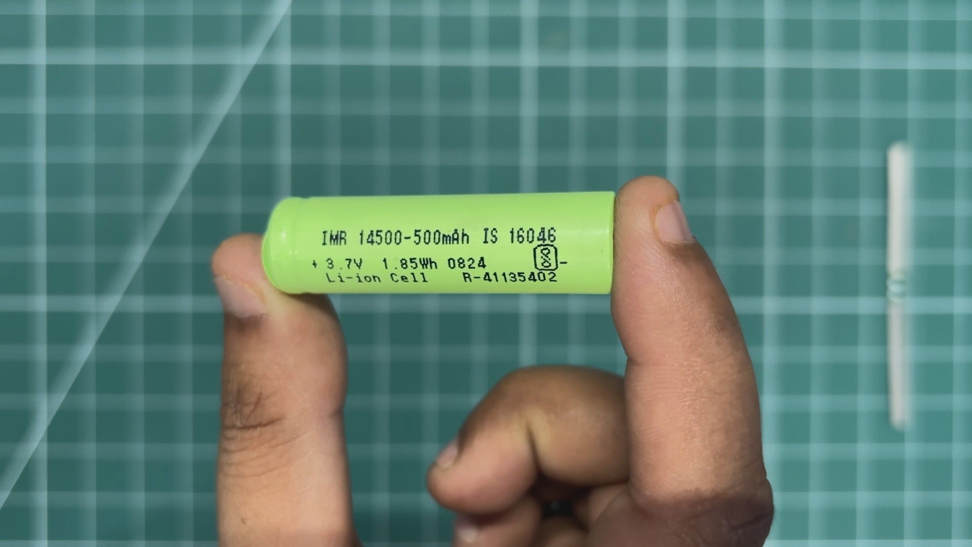
    Instead, we decided to use a lithium-ion cell in a different form factor. We selected a 14500 cell, which is essentially a smaller version of a 18650 cell with roughly half the capacity.

    Here, we are using a 3.7V 500mAh Li-ion cell.

    The cell comes bare, without any PCM circuit. A PCM circuit is mandatory when a lithium cell is being used alone without any dedicated charging/discharging circuitry. What this PCM does is provide low-cut, high-cut, and short-circuit protection functions that protect the cell and make sure it doesn’t explode like a firecracker.

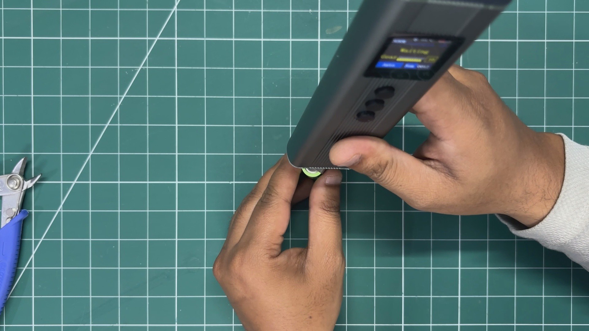
    For adding the PCM to the cell, I used a new tool in my arsenal: a handheld TIG welder. This is an extremely helpful tool while working with cells because it ensures we don’t directly touch the lithium cell terminals with a soldering iron. Touching the terminals with a hot soldering iron can degrade the cell and reduce its capacity.

    Here’s how we made the connections between the PCM and the cell:

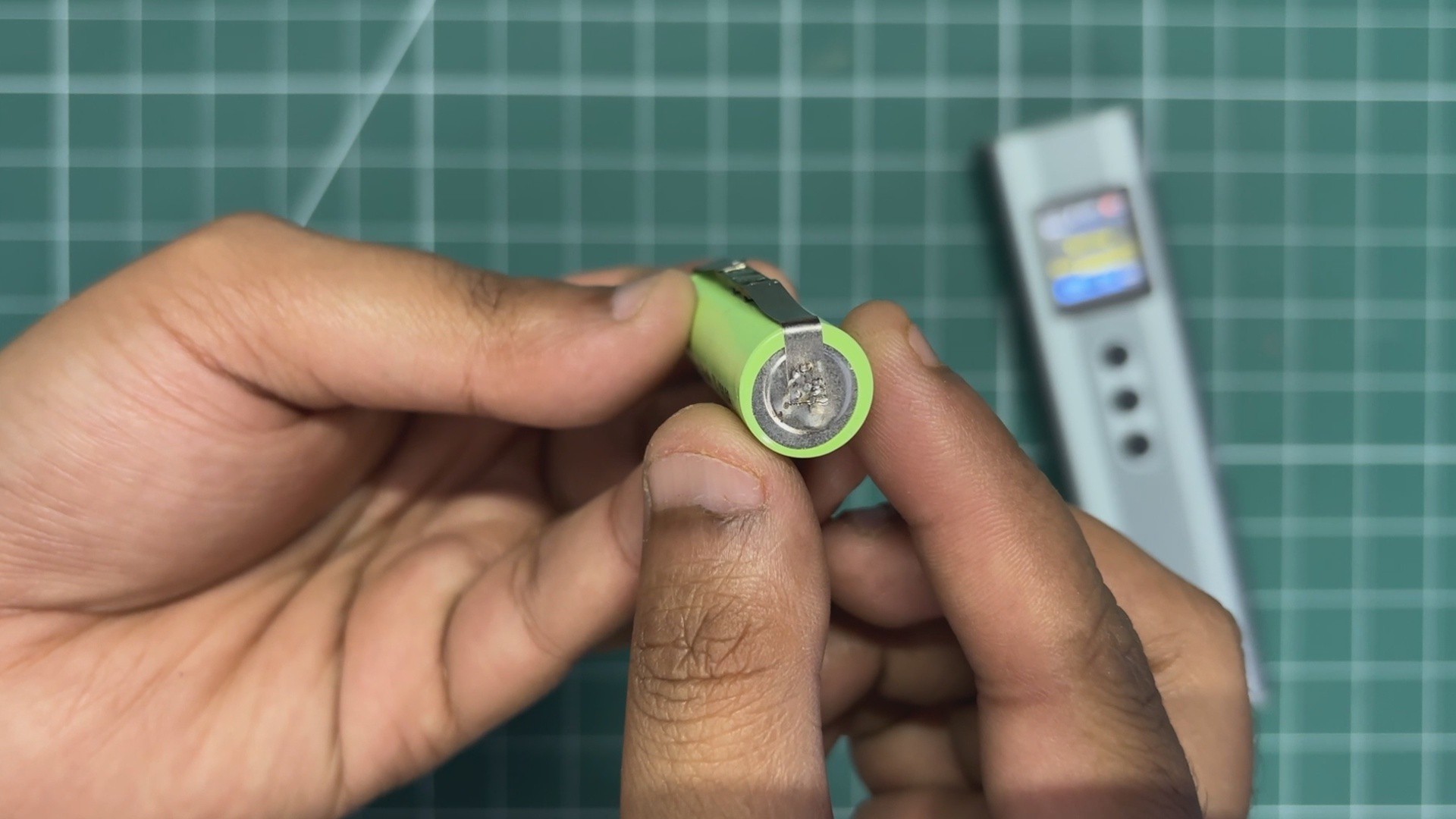
    • The PCM comes pre-soldered with two nickel strips. We placed the PCM with the cell and cut off the excess length of the nickel strips.
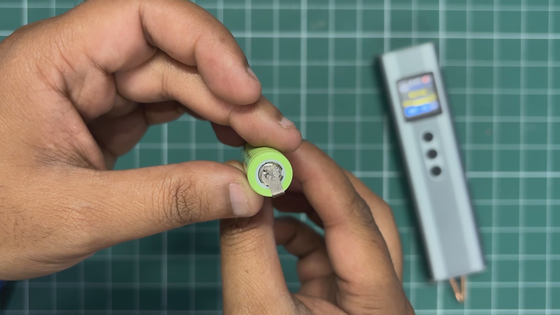
    • Then we bent the strips by aligning them with the cell terminals. Using the TIG welder, we spot-welded the nickel strip to the positive terminal first. We did two to three weld points for a stronger connection.
    • After that, we turned the cell over and repeated the same process for the negative terminal.
    • Once the connections were done, we added wires to the P+ and P− terminals of the PCM, then used a multimeter to make sure we were getting an output voltage. This confirmed that our cell was working properly.

    Here’s why this PCM is important: we will be connecting this cell to the 5V input of an ESP32 DevKit. This means that when we plug a Type-C cable into the ESP32, the cell will start charging from 5V. But if the cell voltage goes above 4.2V, the cell could potentially go boom. The PCM prevents this from happening. When the voltage reaches 4.2V, it cuts the connection between B+ and P+, stopping the charging process.

    The same goes for low-voltage protection. The PCM cuts the power when the cell reaches around 2.2V, which is the recommended lower discharge limit.

    I have also prepared a video showing the construction process of this part, which you can watch.

  • 3
    FRONT BODY ASSEMBLY

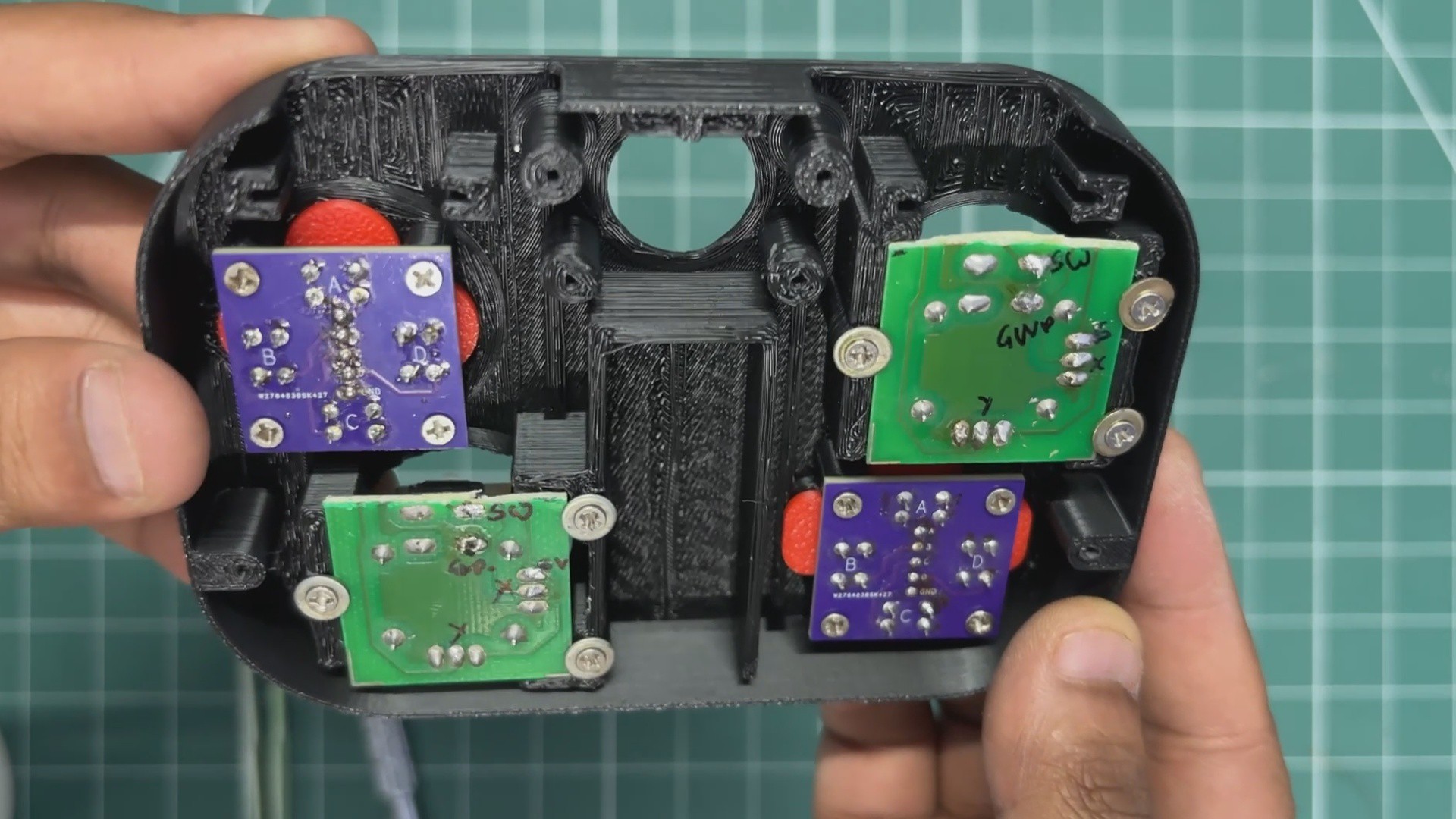
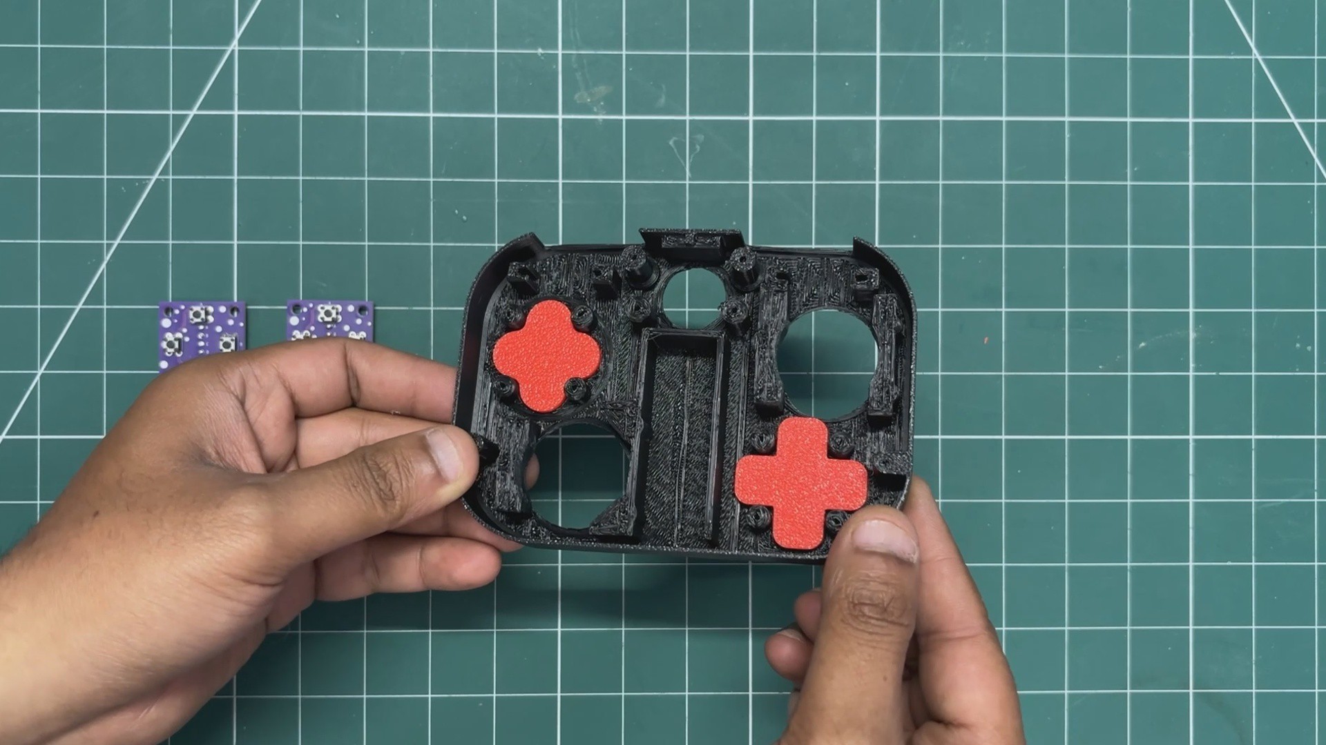
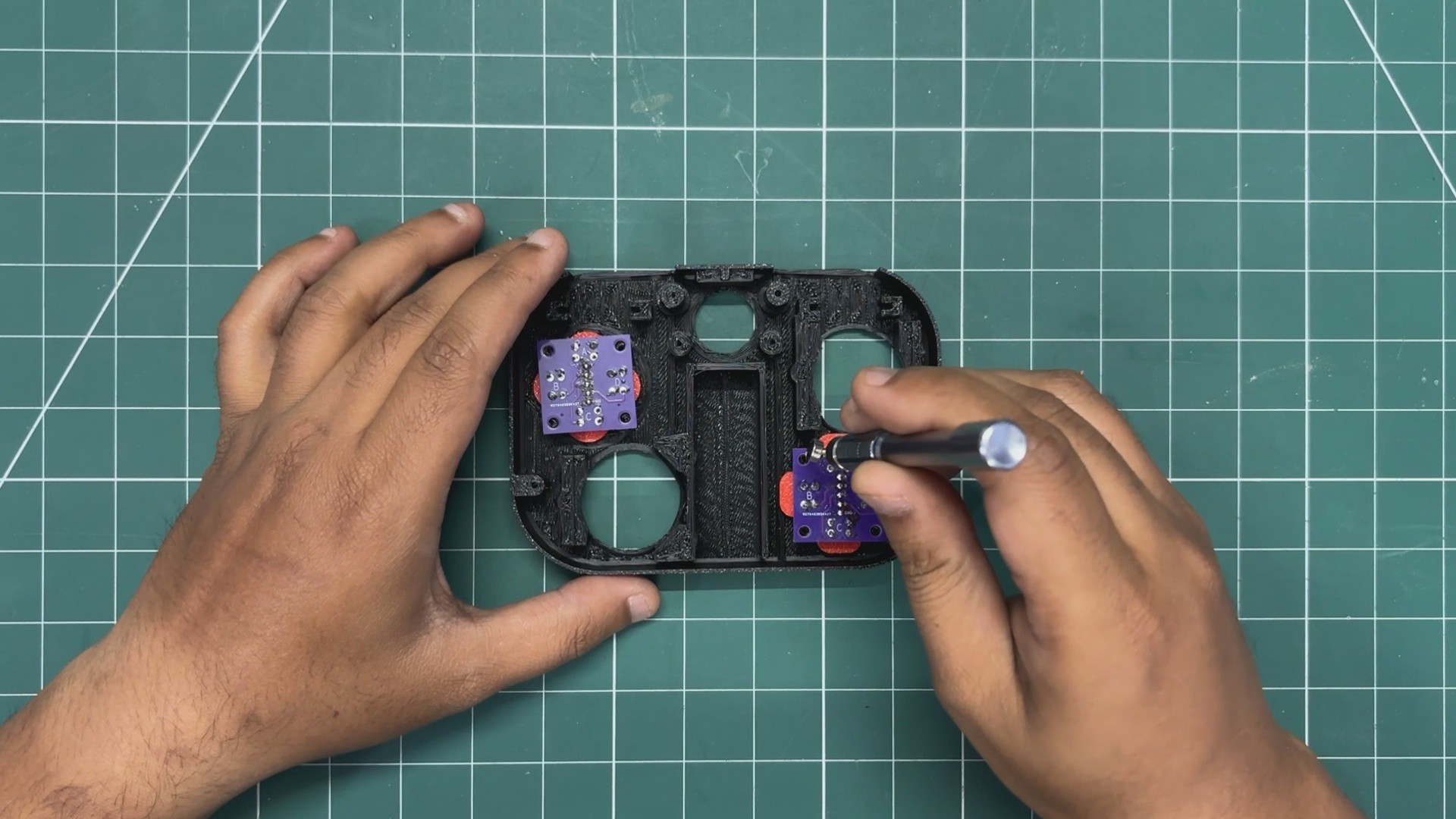
    We began the assembly process by placing the D-pad button and XYAB buttons into their positions from the inside of the front body.

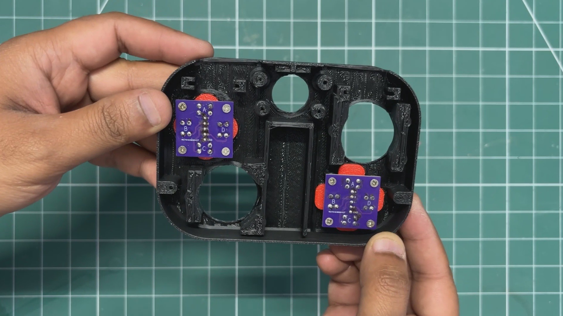
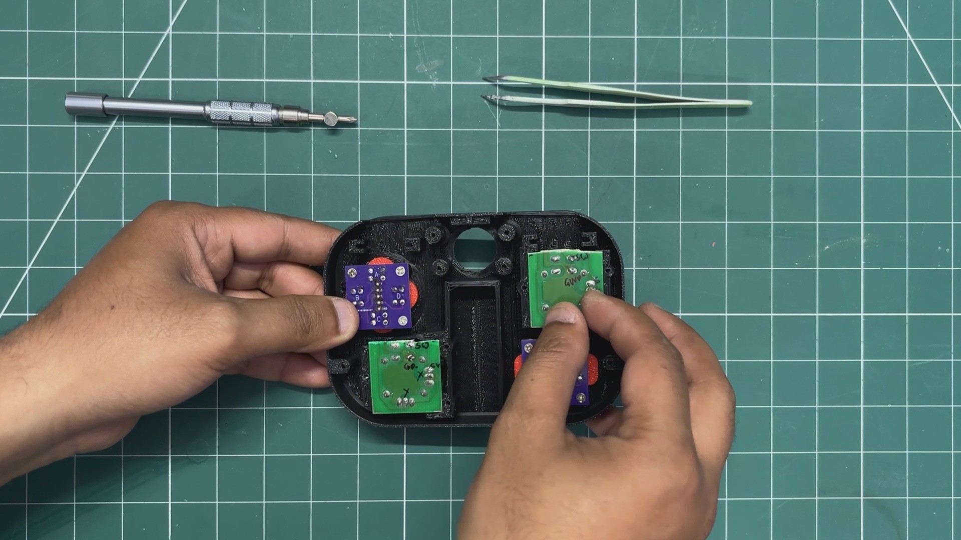
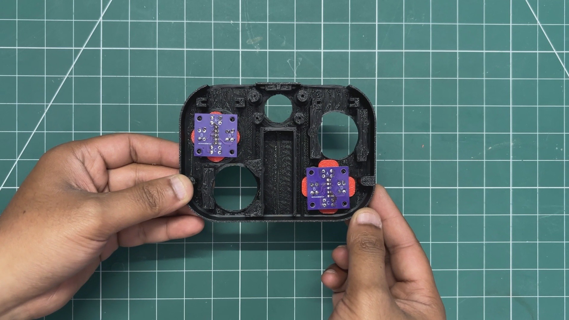
    Next, the button boards were placed over the D-pad and XYAB buttons and aligned with the screw bosses. We then used four M2 screws for each PCB to secure them in place.

    Similarly, the analog joystick modules were positioned over their mounting locations and secured using M2 screws. We used washer-head screws here to keep the joystick modules firmly in place.

View all 9 instructions

Enjoy this project?

Share

Discussions

Does this project spark your interest?

Become a member to follow this project and never miss any updates