 Juan Flores
This project is partially related to my previous one, the PowerTimer, where I focused on reducing idle consumption to maximize battery life. But I wanted to push the boundaries a little further. After coming across Jasper's solar harvest module, I was inspired to create an environmental sensor that could theoretically run forever using very little indoor solar energy, mitigating long-term chemical degradation by swapping batteries for supercapacitors.
Since I consider this an experimental project, I’ll give you the main takeaways upfront, and then we will dive deep into the technical process:
Is it possible to achieve an unlimited operational lifespan using just a solar panel, a power harvester, and intense optimization?
Potentially yes, BUT we need to touch grass here... it heavily depends on the physical placement of the device. We also had to make several engineering trade-offs; for instance, I had to implement a few "hacks" to make the active cycle ultra-fast, meaning we can't transmit massive data telemetry bursts.
That being said, we now have a very solid ground to start working on more complex implementations.
I made a video to walk you through the entire design and assembly process. It's in Spanish (I struggle a lot recording myself, so it's pretty tough to do it in English for now, but I guess YouTube's auto-translate will do its magic!)
(Available on Sunday afternoon)
Architecture
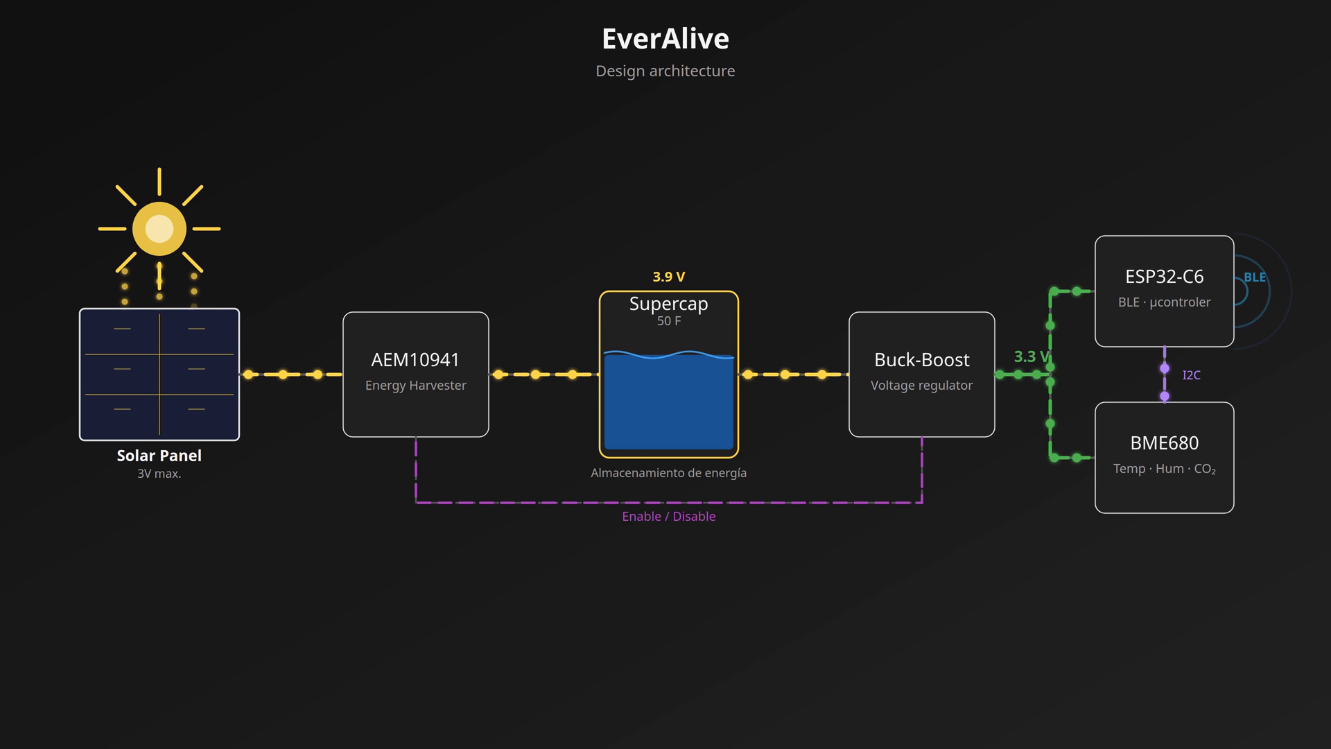
The main core philosophy here was to keep things simple. Instead of over-engineering too many custom workarounds, I tried to rely on the default chip configurations as much as possible.
- Power Harvester: This IC captures solar energy and manages the supercapacitor charge. For this specific use case, it is vital to have a highly sensitive harvester capable of squeezing every single photon out of any situation (including faint indoor light).
- Solar Panel: It is crucial to use a panel with an open-circuit voltage below 5V, as that is the absolute maximum supported input for the harvester. Since the objective is indoor operation, an amorphous panel would be ideal compared to a polycrystalline one. However, they are quite hard to source right now, so I am prototyping with a polycrystalline panel for the time being.
- Supercapacitor: Instead of a standard Li-Po battery, I opted for a supercapacitor as the primary energy reservoir. I found some relatively new hybrid capacitors that mimic the voltage behavior of Li-Po batteries, making power management much easier. The main benefits over traditional cells are an exponentially higher charge/discharge cycle life without degradation, and they are significantly safer to operate.
- Buck-Boost Converter: It might not seem like the most exciting part of the BOM, but selecting the right one is vital. On one hand, we need a rock-solid, stable output rail to feed the MCU and sensors. On the other hand, it must feature an ultra-low quiescent current to prevent draining our power reservoir while the system is sleeping.
- MCU: The requirements here were clear: excellent low-power sleep modes, minimal current draw in deep sleep, and wireless capabilities (BLE, Zigbee, or Thread—Wi-Fi wasn't mandatory).
- Sensor: You could use almost anything here, but the chosen telemetry must be compatible with an ultra-fast "wake up, sample, transmit, and back to sleep" duty cycle (we want to avoid anything that requires long, continuous sampling times). Naturally, it needs a proper low-power standby mode.
Schematics and PCB
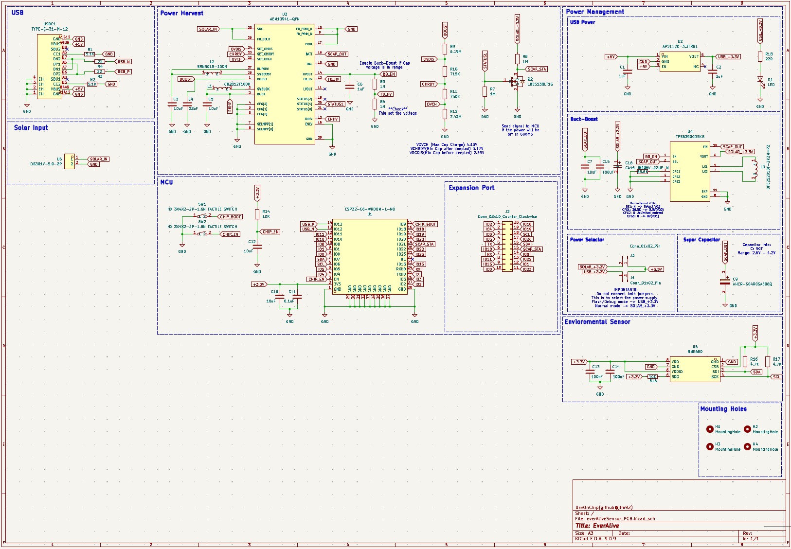
Let's start with the power harvester. I chose the AEM10941 from E-Peas. The technology this company is developing is impressive—they even have models capable of harvesting energy from thermal changes.
I picked this specific IC due to its extremely low-power cold-start capabilities: it only requires 380mV and 3µW to kickstart the harvesting process. Additionally, it supports various energy storages (like single/multi-cell Li-Pos or supercapacitors) and allows you to configure the exact upper and lower charge voltage thresholds via resistors.
Following Jasper's design philosophy, I used the harvester's status output as the Enable signal for the main buck-boost converter. This is a fantastic safety feature because the harvester’s native output rail doesn't provide boost functionality, and its maximum current output is too low to drive the MCU during transmission bursts.
For the storage element, I selected the ABRACON AHCR-S04R0SA506Q supercapacitor. It operates in a 4.2V to 2.5V range (essentially behaving like a standard Li-Po cell), features a very low self-discharge rate, packs 50 Farads of capacity, and most importantly, comes at a reasonable price.
The buck-boost converter handling the rail is the TPS63900. It features an operating input range of 1.8V to 5.5V and an astonishingly low 75nA quiescent current. It fits our design requirements like a glove.
Moving on to the core intelligence: the MCU chosen is the ESP32-C6. Within the Espressif ecosystem, this is likely the chip with the lowest deep sleep consumption, and its multi-protocol wireless stack (Wi-Fi 6, Thread, Zigbee, and BLE) gives us massive flexibility. If one protocol fails to meet our strict energy budget, we can easily swap to another. As a side note, if I were focusing strictly on raw sleep numbers, I probably would have chosen a Nordic Semiconductor MCU, but I didn't have a dev board on hand.
For the environment sensor, I went with the BME680. To be completely honest, it’s probably not the best choice for this specific project. It’s an incredible sensor, but its main feature—the gas index sensor—requires at least 150ms of heater activation time to get a reading. Without continuous tracking, the data isn't great. For future revisions, a much simpler, cheaper sensor tracking just temperature, humidity, and pressure would cut down active time drastically.
Finally, for flashing and debugging, I added a USB-C interface coupled with a 5V-to-3.3V linear regulator and an onboard physical jumper to select the active power source. It's a simple and potentially hazardous layout if you mess up the jumper placement during development, but for a prototype, it gets the job done.
Regarding the PCB layout, there isn't too much complex routing. The components have plenty of breathing room since the overall dimensions of the board were dictated by the footprint of the solar panel. Initially, the supercapacitor was meant to sit on the bottom layer, but I realized I could shrink the enclosure profile by moving it to the top face next to the solar panel connector, keeping it away from any high-heat paths.
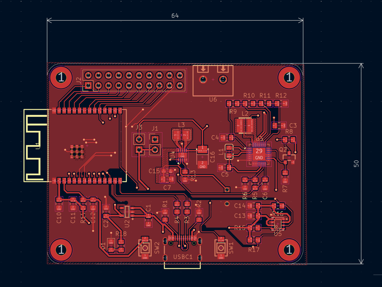
(The sensor is isolated in a corner to sit directly next to the enclosure's ventilation grille)
Firmware
For the software stack, I developed the firmware using the official ESP-IDF SDK. The main reason behind this choice was the granular control it offers over the bootloader configuration, allowing us to shave off precious milliseconds from the boot sequence.
I completely disabled all bootloader logs, UART working traces, and ROM firmware verification checks at startup. With these optimizations, we managed to cut roughly 200ms from the entire power-on process.
When designing the wireless topology, I decided to stick with BLE. My initial idea was to implement Matter via ESPHome to get effortless integration into Home Assistant. However, after some profile testing (maybe I missed an optimization step), the full wake-and-connect sequence took a painful 7 seconds!
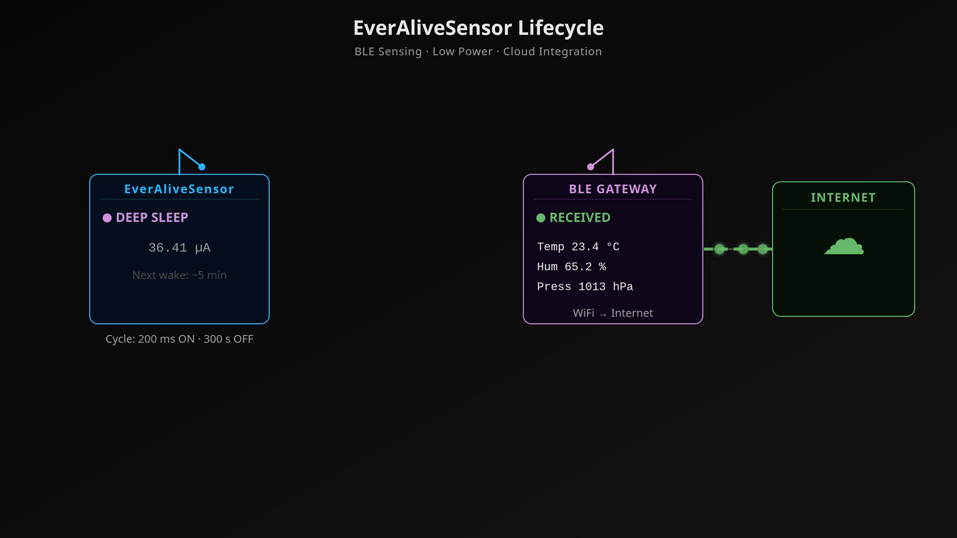
That is an eternity for an energy-harvesting node. So, I stripped everything down to a stateless BLE configuration. The device never negotiates an active connection with a central router; instead, it formats the sensor telemetry into a compact 6-byte raw payload and injects it directly into the Manufacturer Specific Data field of a standard BLE advertisement broadcast.
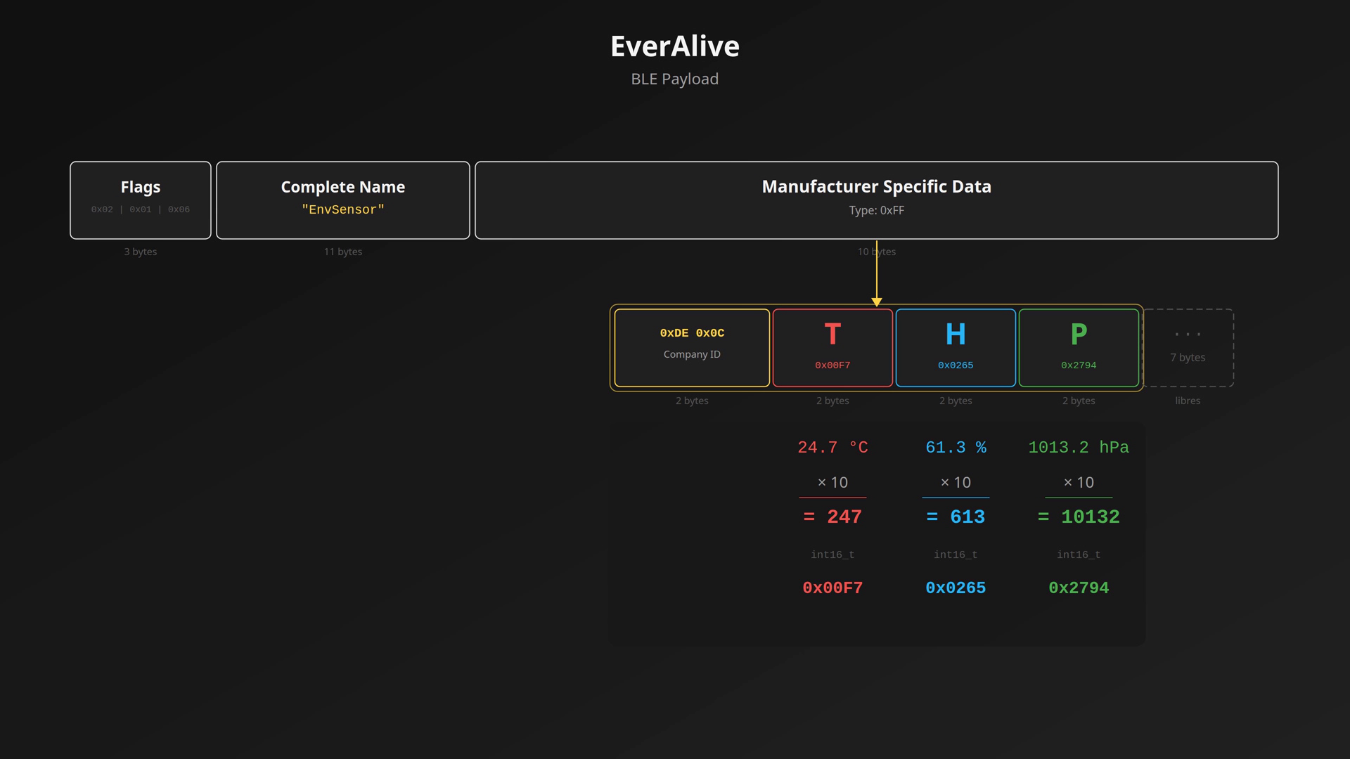
With this approach, the active overhead drops to a mere 20ms. The obvious downsides are that the data is transmitted in the clear and there is no handshake acknowledgment to guarantee the packet was received. But hey, it's incredibly fast, and indoor room temperature isn't exactly sensitive classification data.
The optimized firmware routine follows this exact loop:
- Wake up / Boot.
- Sample the BME680 (skipping the gas heater ).
- Structure the 6-byte raw payload.
- Broadcast the advertising packet 4 times over a 20ms window.
- Kill all peripherals and enter Deep Sleep for 5 minutes.
You might think a 20ms advertising window is way too tight for a receiver to catch, and footprints normally it would be. To solve this, I set up a second ESP32-C6 running as a continuous bridge router.
This router runs in promiscuous mode, listening to the BLE spectrum constantly and filtering specifically for our node's MAC address. The moment it captures a packet, it prints the raw metrics to the terminal. From there, it's trivial to bridge that data over to MQTT or the internet.
Power Consumption Study & Mathematical Validation
To validate the theoretical lifespan of the everAliveSensor, I carried out a basic DIY characterization of the Aliexpress polycrystalline solar panel (rated at 3V, with no datasheet provided) and measured the current profiles of the PCB using a power profiler.
1. Solar Panel Empirical Harvesting Data
Measurements taken at short circuit (Isc) and open-circuit voltage (Voc):
| Scenario | Voltage (V) | Current (mA) |
| Direct Sunlight | 3.4 | 90.0 |
| Indoor Ambient Light (with curtains) | 2.5 | 1.2 |
| Ultra-low Indoor Light (Monitor glare only) | 1.2 | 0.002 |
As expected, performance is great under direct sunlight but drops significantly inside a room, which proves why aggressive firmware optimization is non-negotiable.
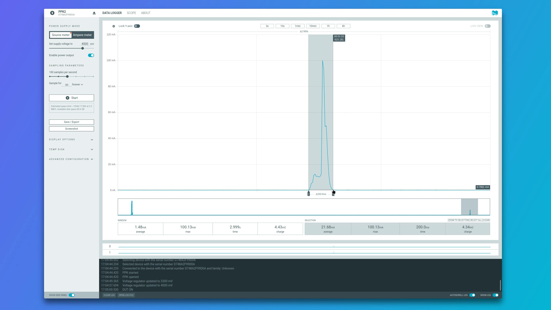
2. Hardware Power Profiling
- Active State: Average current draw I_active = 21.68 mA during an active window of t_active = 200 ms.
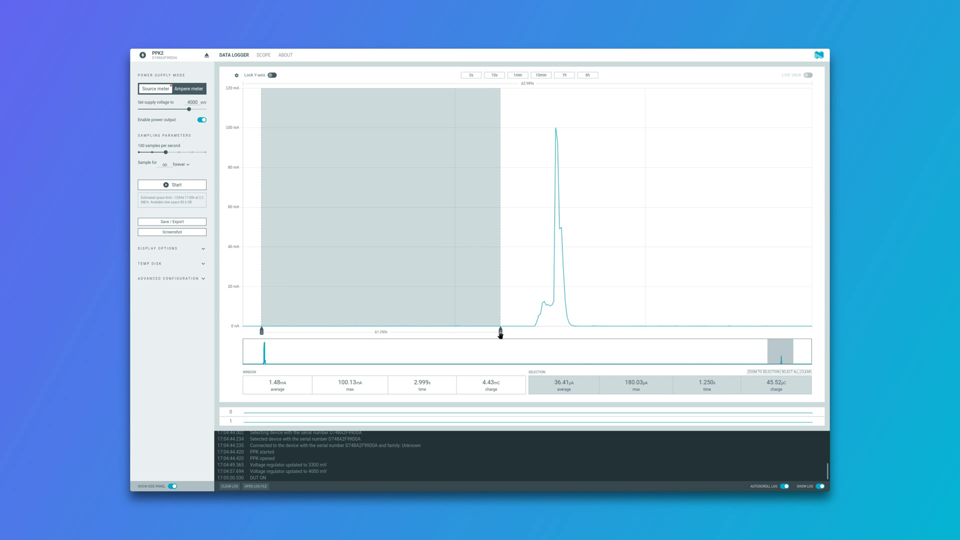
- Sleep State: Average deep sleep leak current I_sleep = 36.41 µA over a sleep window of t_sleep = 299.8 s (completing the 5-minute cycle).
3. Mathematical Model & Capacitor Capacity
To make the energy balance easier to visualize, let's use the exact values from the video characterization. First, we calculate the time-weighted average current (Imed) over a full 300,000 ms (5-minute) duty cycle, converting all units to microamperes (µA):
With an average current of 50.8 µA, the total daily capacity consumption scales over 24 hours as follows:
Now, let's find out the usable capacity of our 50 Farad supercapacitor. The AEM10941 thresholds and the TPS63900 buck-boost keep our usable voltage window between 4.2V (max charge) and 2.5V (cutoff threshold). The usable charge in Coulombs is defined by:
Converting Coulombs to mAh (where 1 mAh = 3.6 Coulombs):
With a usable capacity of 23.61 mAh and a daily draw of 1.22 mAh, the device can survive in absolute darkness for:
4. Solar Panel Scenario Analysis
Let's cross-reference our daily consumption requirement (1.22 mAh/day) with the empirical data gathered from our polycrystalline solar panel to see under which conditions the node is viable:
- Scenario 1: Direct Sunlight (90 mA output): The panel can harvest the entire day's energy budget in just 49 seconds. In outdoor conditions, the platform is overwhelmingly sustainable.
- Scenario 2: Indoor Light with Curtains (1.2 mA output): To cover the 1.22 mAh daily budget, the panel needs to receive this ambient light level for roughly 1 hour per day (approx. 61 minutes). This scenario is highly viable for standard office spaces or rooms with regular indirect daytime illumination.
- Scenario 3: Ultra-low Indoor Light / Monitor Glare (0.002 mA output): Even if the device is exposed to this faint light for 24 hours straight, it would only harvest 0.048 mAh/day, which covers less than 4% of the system's needs. Under these conditions, the node will slowly deplete the supercapacitor.
Conclusion
The everAliveSensor proves that building a battery-free, "immortal" IoT platform is absolutely achievable, but it is not magic—it is an exercise in strict energy budgeting.
Whether the node runs indefinitely depends entirely on three physical variables: the exact placement of the sensor (lux levels), the hours of indoor light it receives daily, and the transmission frequency programmed in the firmware. Thanks to the massive 19-day buffer provided by the 50F hybrid supercapacitor, the system can easily bridge dark weekends or cloudy weeks, establishing a rock-solid foundation for permanent indoor telemetry.