 Roni Bandini
Symple Synth (sic) is a very simple polyphonic sound generator designed to be easy to build and to make use of recycled electronic components such as potentiometers, resistors, capacitors, and diodes.
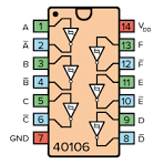
Hex Schmitt Trigger
At the heart of the device is a simple integrated circuit called a Hex Schmitt Trigger, available from electronics suppliers for around US$1. It may be labeled as 40106, CD40106, 4584, or 74C14. Prefixes and suffixes usually do not matter and the circuit will work the same way. For example, the HF40106BP works perfectly well. However, if the part number includes different characters in the middle, it may not operate at the required voltage. The 74HC14, for instance, is not suitable because of the "HC" designation.
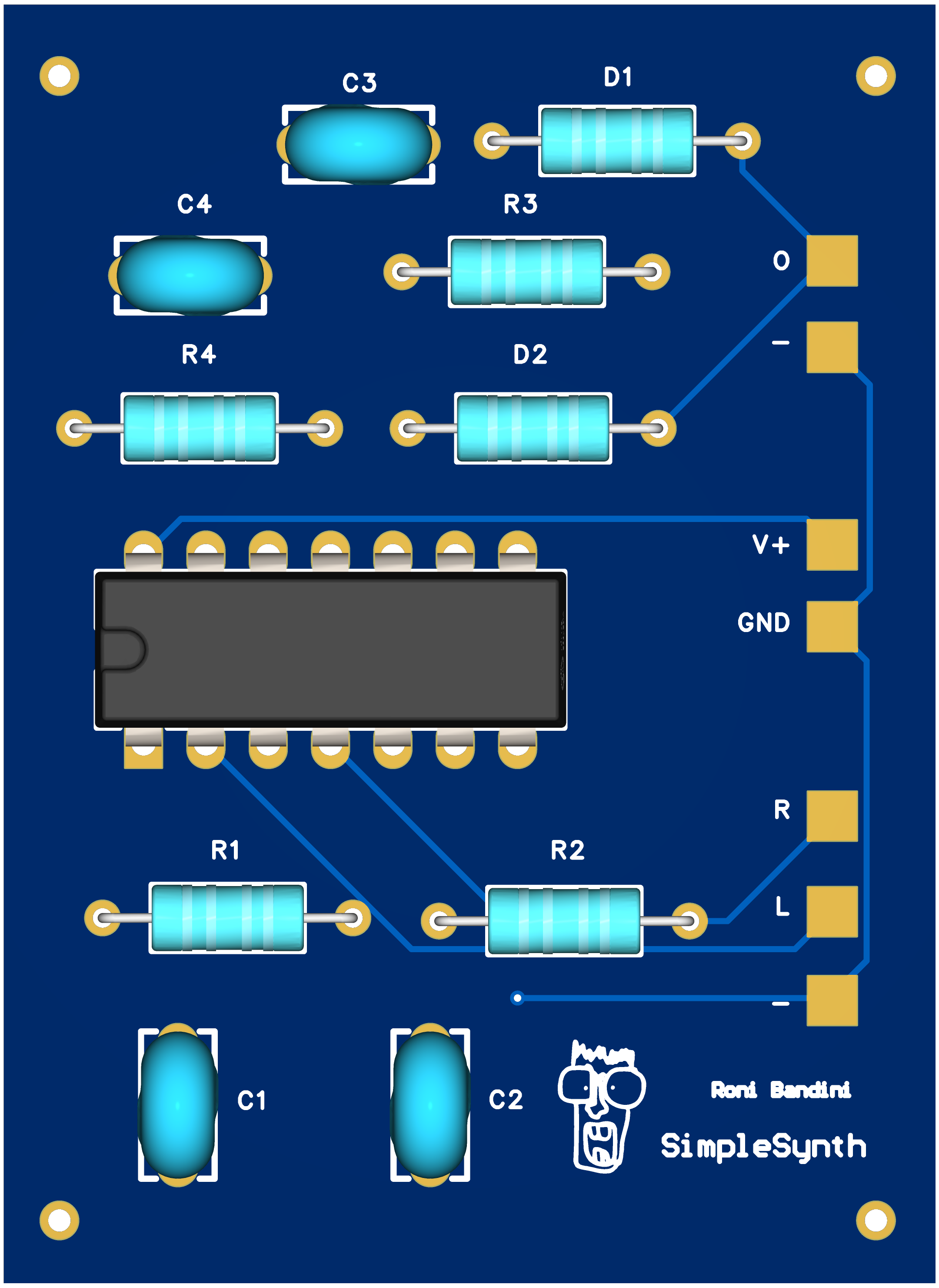
PCB or breadboard
To simplify the assembly process, I quickly designed a PCB that can be ordered from PCBWay. If you do not want to spend money on a custom board, or if ordering one is not practical, it is also possible to build a version of the Symple Synth on a breadboard (see note * below).
Which Components to Use
Salvaging components from discarded electronics is straightforward. Heat the solder joints with a soldering iron or hot-air station, then either remove the solder with a desoldering pump or extract the components directly using pliers.
Useful parts include resistors, diodes, capacitors, transistors, potentiometers, toggle switches, and audio jacks. Experiment with whatever you can find.
If you have a surplus of parts and can be selective, these are recommended:
- 1N914 or 1N4148 diodes
- Linear potentiometers from 10 kΩ to 100 kΩ, or photoresistors. Fixed resistors can also be used.
- 0.1 µF ceramic capacitors or 8.2 µF electrolytic capacitors. Larger capacitors tend to produce lower-pitched, metronome-like sounds, while smaller capacitors generate higher frequencies that can even reach the ultrasonic range.
In addition, you will need:
- A 9V battery with a battery clip
- A toggle switch
- Two 3.5 mm female audio jacks
- An IC socket (optional)
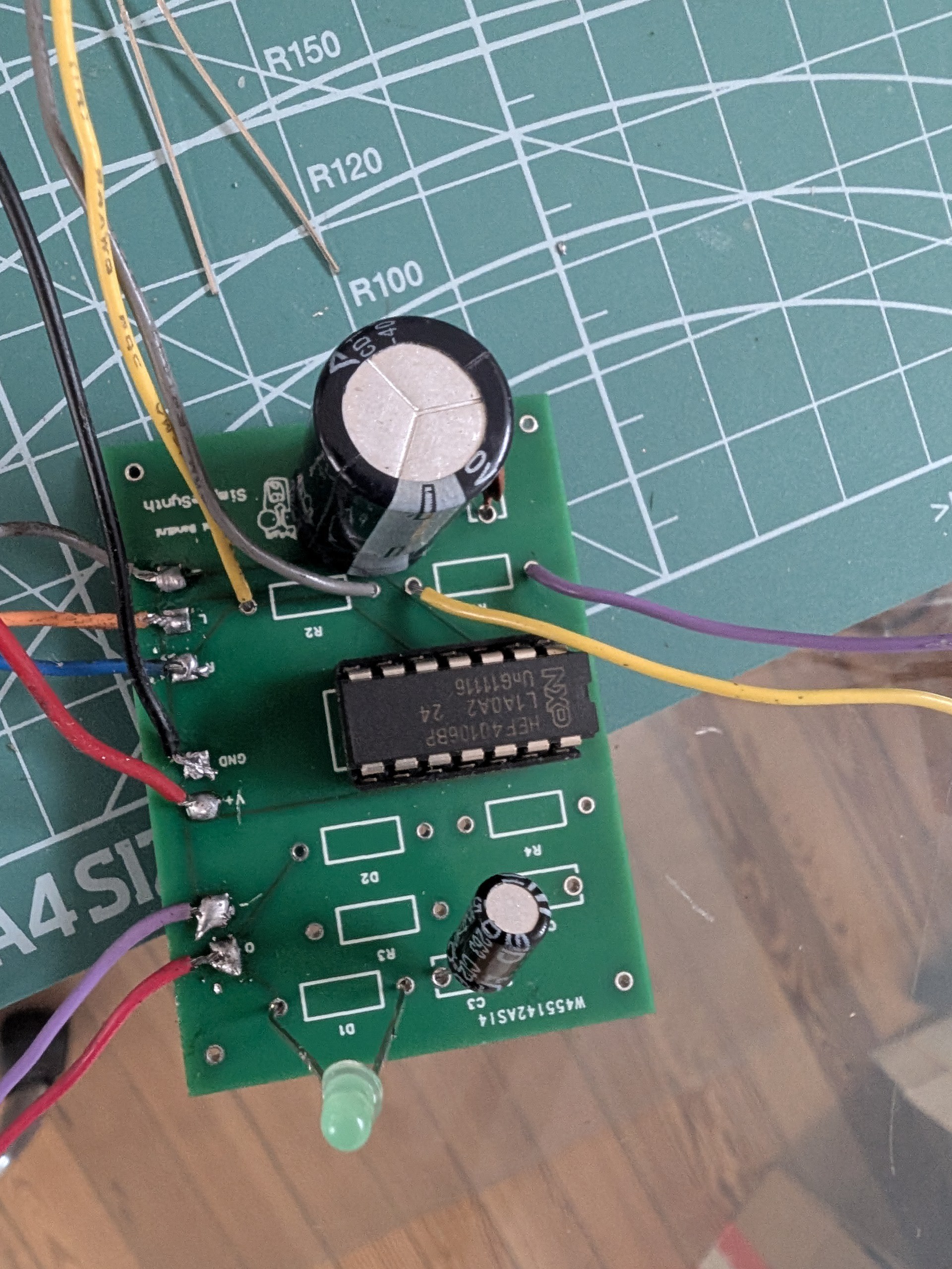
How to Assemble the Components
Place the integrated circuit in the row of 14 holes marked with the IC outline. Next, install the capacitors in positions C1 through C4, the diodes in D1 through D4, and the potentiometers or LDR photoresistors in positions R1 through R4.
For the audio connections, connect one output jack to the pads labeled R and L, and the second output jack to the pads labeled O and –.
Finally, connect the 9 V battery to the V+ and GND terminals.
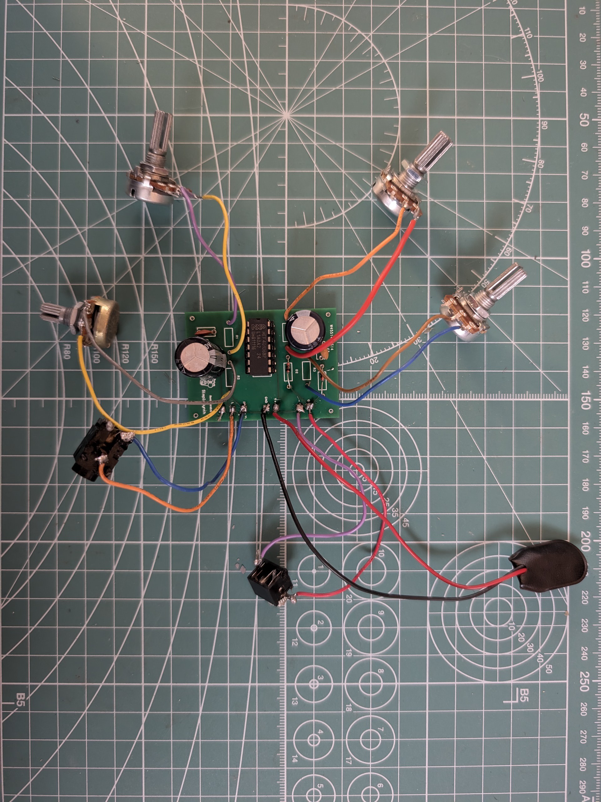
About the Channels
The circuit is divided into two sections. The section without the diodes sends signals to the left and right channels of a stereo output jack. Depending on the components used, the two channels may have different volume levels. This can be corrected either with the balance control on your amplifier or by adding 10 kΩ resistors to each output.
The diode section combines the audio from each channel using ring modulation. In this case, balancing the output levels is generally unnecessary, as the signals are mixed together through the modulation process.
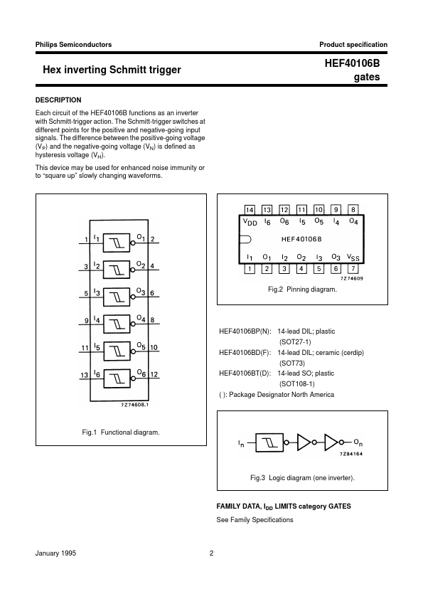
More About the Hex Schmitt Trigger
The integrated circuit contains six inverters. Each inverter takes a logic high (1) and turns it into a logic low (0), or takes a logic low (0) and turns it into a logic high (1).
When 9 V is applied to the input, the inverter drives its output low. That low signal is then fed back to the input through the resistor-capacitor network, causing the input voltage to change until the inverter switches state again. The process repeats continuously, creating a square wave oscillator.
The rate at which the output flips between high and low states depends on the values of the resistor and capacitor. Changing either component changes the oscillation frequency and therefore the pitch of the sound produced.
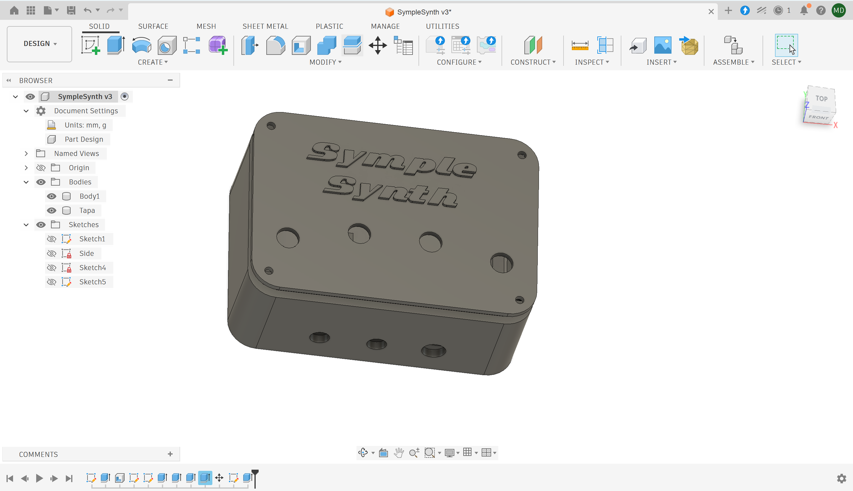
3D-Printed Enclosure
I designed a custom enclosure that can be 3D printed in PLA without the need for support structures.
When printing the lid, pause the print just before the...
Read more »
 Sagar 001
 Pierre-Loup M.
 Zeppelin Design Labs
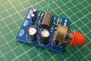
 ElectroBoy