Close
0%
0%

ESP32 Walkie Talkie

Utilizes an I2S mic and I2S amp using an ESP32 with the ESPNOW wireless protocol to communicate audio wirelessly at over 600+ meters.

Similar projects worth following
These walkie talkies send voice directly from one ESP32 to another using ESP-NOW. Audio is captured through an I2S microphone, processed in firmware, compressed, transmitted wirelessly, decoded on the receiving side, and then played through a speaker amplifier and internal speaker.

The system includes:

push-to-talk voice communication
20 logical channels
OLED user interface
link detection
battery monitoring
signal indicator
volume control
menu-based apps and settings
onboard diagnostic logging

The same hardware can also be reused as a wireless controller for other ESP32 or Wi-Fi projects. Since each unit already has a screen, buttons, battery power, and radio capability, it can be adapted for robots, RC systems, lights, or other IoT devices.

ESP32 ESP-NOW Walkie Talkies

For full firmware, wiring details, documentation, and project files, see the GitHub repository: github.com/GuzziFlipFlops/ESP32-Walkie-Talkie

Overview

This project is a pair of custom digital walkie talkies built around ESP32 boards with external antennas, OLED displays, I2S audio hardware, and custom 3D-printed casings. They communicate directly with each other using ESP-NOW, so they do not need a router, hotspot, or cellular connection to work.

The goal was to build a real handheld communication system, not just a desk prototype. Each unit has its own screen, buttons, battery monitoring, volume control, and a menu-driven interface. The result is a compact embedded device that combines wireless communication, real-time audio, and custom hardware design into a fully self-contained build.

What it does

These walkie talkies send voice directly from one ESP32 to another using ESP-NOW. Audio is captured through an I2S microphone, processed in firmware, compressed, transmitted wirelessly, decoded on the receiving side, and then played through a speaker amplifier and internal speaker.

The system includes:

  • push-to-talk voice communication
  • 20 logical channels
  • OLED user interface
  • link detection
  • battery monitoring
  • signal indicator
  • volume control
  • menu-based apps and settings
  • onboard diagnostic logging

The same hardware can also be reused as a wireless controller for other ESP32 or Wi-Fi projects. Since each unit already has a screen, buttons, battery power, and radio capability, it can be adapted for robots, RC systems, lights, or other IoT devices.

What makes it work well

A basic wireless voice demo is not that hard. Making it work like a real handheld device is harder.

To improve usability, I added several firmware features that make the system much more robust:

  • audio compression so voice fits efficiently into ESP-NOW packets
  • jitter buffering so received audio plays more smoothly
  • packet-loss concealment to reduce harsh dropouts
  • heartbeat packets for link detection
  • weak-link redundancy that sends duplicate frames when signal conditions get worse
  • onboard telemetry logging for range testing and diagnostics

These details matter because wireless performance changes constantly with interference, antenna placement, and obstacles. Instead of guessing why the link gets worse, the firmware records data such as RSSI, link quality, jitter depth, duplicate packets, and missing-packet behavior.

Hardware

Each walkie talkie is built around an ESP32-U style development board with an external antenna. The supporting hardware includes:

  • SSD1306 OLED display
  • I2S microphone
  • I2S speaker amplifier
  • internal speaker
  • potentiometer for volume
  • six push buttons
  • LED
  • 3.3 V laser module
  • battery voltage monitoring
  • lithium battery power system
  • custom 3D-printed enclosure

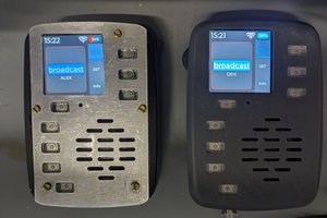
The project has two physical versions, a black walkie and a grey walkie. They are wired slightly differently, so the firmware supports separate board profiles instead of forcing both devices to be identical. That made the system easier to maintain and much more practical to develop.

Design and build process

The electronics were first tested outside the enclosure, subsystem by subsystem. After confirming the power system, display, microphone, buttons, amplifier, and battery measurement were working, everything was arranged into the printed casing.

One of the biggest lessons from this build was that internal layout matters almost as much as the circuit itself. The second unit has cleaner routing, thinner wiring, and better internal placement than the first version. That made it easier to close, easier to debug, and much easier to improve.

This project ended up being a combination of several disciplines at once:

  • embedded firmware
  • wireless protocol work
  • digital audio handling
  • power and battery integration
  • user interface design
  • 3D enclosure design

Challenges

Audio over ESP-NOW

ESP-NOW is fast and convenient, but it is not a complete voice-radio solution on its...

Read more »

esp32_walkie_talkie.bin

walkie talkie firmware

octet-stream - 917.45 kB - 06/11/2026 at 00:14

Download

walkie_talkie_top_cover.stl

3d printed case part

Standard Tesselated Geometry - 2.34 MB - 06/11/2026 at 00:07

Download

walkie_talkie_bottom_case.stl

3d printed case part

Standard Tesselated Geometry - 308.48 kB - 06/11/2026 at 00:07

Download

walkie_talkie_OK_button.stl

3d printed case part

Standard Tesselated Geometry - 379.77 kB - 06/11/2026 at 00:07

Download

walkie_talkie_top_buttons_grid.stl

3d printed case part

Standard Tesselated Geometry - 297.35 kB - 06/11/2026 at 00:07

Download

View all 7 files

  • 1 × ESP32 WROOM32 /w U.FL
  • 1 × ESP32 WROOM32 /w U.FL
  • 1 × INMP441 I2S Mic
  • 1 × INMP441 I2S Mic
  • 1 × MAX98375A Speaker Amp

View all 24 components

  • 1
    What to do if you want to build your own
    1. Fork the github repository: github repo walkie talkie
    2. Review the circuit diagram and photos.
    3. Add or modify CAD files in the repository
    4. Wire one black-style or grey-style unit, or create a new board profile.
    5. Set the correct peer MAC addresses in menuconfig
    6. Build and flash the firmware.
    7. Test audio at short range first.
    8. Tune mic gain, speaker gain, channel, and antenna placement.
    9. Test range outdoors with clear line of sight.

    If your wiring differs, add a new board profile instead of hardcoding changes over the existing black/grey profiles. That keeps the firmware easier for other builders to understand.

View all instructions

Enjoy this project?

Share

Discussions

Ken Yap wrote 06/13/2026 at 02:26 point

That's a strange speaker opening. Looks like connectors. Did you reuse an existing case?

  Are you sure? yes | no

Aditya Verma wrote 06/14/2026 at 16:01 point

Thank you for looking at my project,

The design is similar to a real walkie talkie, (like a baofeng), are you talking about the several holes I have for the speaker?

  Are you sure? yes | no

Ken Yap wrote 06/14/2026 at 16:07 point

Yeah those holes that look like connectors but are not.

  Are you sure? yes | no

Aditya Verma wrote 06/14/2026 at 16:11 point

I see what you're talking about. I added those holes to help open the speaker's output. When I printed the model on my ender 3, the holes got covered up and became solids, so I added larger rectangular holes, but after I got a new printer the holes came out much better, I didn't really feel like removing them.

  Are you sure? yes | no

Oliver Ridler wrote 06/13/2026 at 00:05 point

This is an impressive project, well done!  

600m range is surprising, how did you achieve such a long range?

Also I wonder why having 2 different hardware variants was so important?

I hope you are planning to develop a PCB to simplify all the wiring (and make it more robust).

Cheers

Oliver

  Are you sure? yes | no

Aditya Verma wrote 06/14/2026 at 15:56 point

Thank you for looking at my project,

I achieved the 600m long range by ditching the 2-way handshake espnow normally uses for a 1-way transmitting only protocol. I got rid of the ACK packet that acknowledges that the recieving esp32 recieved the message. This significantly increases range, and the farther you get, the more data loss you'll have (less data integrity), and more stutturs, but at my 600m range, I could still make out what the other walkie talkie was saying. 

I had 2 different hardware variants because when I was soldering them, I mistakenly soldered some components to different pins, this was not intentional, instead of resoldering and risking melting some plastic as I had placed the components in, I decided to just change up the code.


About the pcb- Yeah, the PCB would make wiring MUCH easier. Wiring was hell for me, if you look at the open body for the black walkie talkie, you can see how thick and squished the wires are. I learned and chose to use much higher AWG wires in the 2nd one, making it much cleaner, but yeah, a PCB would make things a lot easier.

  Are you sure? yes | no

Oliver Ridler wrote 06/15/2026 at 11:04 point

There are a few good and free shematic capture and PCB options out there, but I have had great success with Kicad.  JLCPCB and PCBway make great low cost PCBs, recently I have had more success with JLCPCB.   Good luck!

  Are you sure? yes | no

Similar Projects

Does this project spark your interest?

Become a member to follow this project and never miss any updates