 thomaswust79
1. System Architecture and Register-Level Parallel Bus
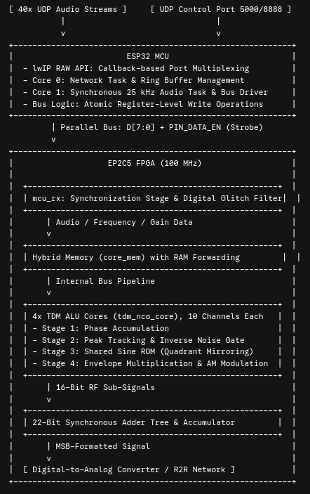
The overall architecture is partitioned into two fundamental domains: the asynchronous network and control domain (ESP32) and the synchronous, deterministic DSP modulation domain (EP2C5).
The Bus Interface: Byte-Wide Register Driving
The transfer of modulation data occurs over an 8-bit wide data bus, flanked by a dedicated enable strobe (PIN_DATA_EN). Rather than utilizing sequential bit-shifting (bit-banging), the MCU leverages the low-level, hardware-near register structure of the ESP32 SoC. By executing atomic writes to the GPIO.out_w1ts (set) and GPIO.out_w1tc (clear) registers, the GPIO states for the entire data byte are manipulated in parallel within a single CPU clock cycle.
The protocol enforces a strict temporal sequence to allow transient states on the physical bus lines to settle before being sampled by the FPGA:
- Data Setup: The MCU calculates the logic bitmask for the byte to be transmitted and writes it simultaneously to GPIOs 0 through 7.
- Strobe Activation: Following a defined nanosecond-scale hardware setup time, the MCU asserts
PIN_DATA_ENhigh. - Strobe Hold & Data Hold Time: The signal remains stable until the FPGA safely captures the data, followed by the atomic clearing of the enable pin.
2. The lwIP RAW Real-Time Network Stack and Port Multiplexing
The central challenge for the MCU firmware lies in the simultaneous management of up to 40 independent UDP ports (one port per transmission channel) at a constant audio sampling rate of 25 kHz per channel.
The Bottleneck of the BSD Socket Model
Deploying the standard POSIX/BSD Socket API (socket(), bind(), recvfrom()) is entirely unfeasible for this application due to the following reasons:
- Context Switch Overhead: Sockets require blocking calls or kernel-level multiplexing via
select(). With 40 active channels, this induces continuous context switching between the application's user space and the TCP/IP stack's kernel space, devastating the FreeRTOS scheduler. - Resource Exhaustion: Each BSD socket instantiates dedicated control structures and thread contexts. Scaling this to 40 ports would rapidly exceed the ESP32's SRAM footprint.
- Data Copy Cycles: Payloads must be copied from the network driver to the lwIP buffer, then to the socket buffer, and finally to the application buffer. This cascade destroys the deterministic timing required for the 25 kHz audio task.
The Solution: lwIP RAW API
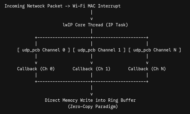
The lwIP RAW API circumvents the OS abstraction layers entirely. It operates on a purely event-driven, callback-based paradigm executing directly within the context of the core IP network thread.
For each audio channel, a Protocol Control Block (struct udp_pcb) is registered and bound to a global callback function via udp_recv(). When a UDP packet arrives at the Wi-Fi MAC, the lwIP core parses the header and immediately executes the registered callback.
This approach yields maximum efficiency:
- Zero-Copy Approximation: The callback receives a direct pointer to the linked buffer list (
struct pbuf). Audio data is iterated and pushed directly into the channel-specific ring buffer without intermediate OS allocations. - Latency Minimization: Devoid of blocking queues, the system achieves the theoretical minimum jitter between packet arrival and buffer update.
- Centralized Port Management: All ports are handled seamlessly through a single linked list of lightweight control blocks.
https://github.com/radiolab81/FPGA_AMWaveSynth/tree/main/mcu_examples/esp32/udp_rx_mcu_tx
https://github.com/radiolab81/FPGA_AMWaveSynth/tree/main/TDM/40ch/udp_rx_mcu_tx
3. FPGA Pipeline: 4-Core TDM and Hybrid Memory Hierarchy
On the FPGA side, the design must strictly adhere to the aggressively constrained resources of the Altera Cyclone II EP2C5 (comprising merely 4,608 Logic Elements and 26 M4K blocks). The solution is a semi-parallel Time-Division Multiplexing (TDM) architecture, distributed across four parallel Arithmetic Logic Unit (ALU) cores.