• Infrared Communication - Sending a 1-second tweet

    Parallel Logic18 分鐘前 0 comments

    I've mentioned previously that part of my motivation for this project was the rock paper scissors concept presented at Supercon 2025 and before that at Burning Man, but wanted to expand on that to encourage longer interactions.  I was also inspired by the RF badge at Supercon 2025 that served as an interesting platform to host a bot in.  So I wanted to make a SAO that could exchange messages, and short messages between users naturally gravitates towards the concept of sharing "tweets".

    Having interacted with the device in the video above, it was a little troublesome to make electrical contact, plus it complicated mass production, so I sought to make a contact-less solution.  However, I've shied away from true RF like WiFi and BLE in part due to the extra resource requirements (either requiring an auxiliary chip or delving in with an ExpressIf solution), and in part because of the hacking-concentric nature of DEFCON and my own unfamiliarity with securing/hardening that kind of solution.  So that left with Infrared as being a more traditional solution better suited to line-of-sight and short distances.


    Each vendor of a TV or other device responding to IR has a slightly different implementation, but categorically you're talking about a ~940 nm wavelength LED emitting light.  To avoid interference from static sources like light bulbs or otherwise, the protocol actually defines the active state as transmitting pulses of IR light at ~38 kHz, and the inactive state as transmitting no light at all.  The traditional protocols also tend to define the data in terms of the length of the signals transmitted - so 600 us or 1200 us of pulses or inactive can encode values of 1 or 0.  Some protocols (ex. NEC) repeat the signal inverted (active is inactive, inactive is active)as a form of error correction.

    To send a 256-character tweet using this protocol at ~1ms off and ~1 ms on per bit, plus doubling the message length for error correction would take ~8 seconds, which feels on the long side if there are potentially other users in the vicinity also using this half-duplex channel (a receiver can only listen to one source at a time - multiple independent transmitters would stomp atop one another, making the channel unusable).  So I was looking for something faster.

    Commercial receivers actually do this 38 kHz pulses = active, no pulse = inactive, decoding for me (I do not get 38 kHz as an input), so it's straight-forward to see the chip claims the minimum detectable signal as 16 cycles of 38 kHz IR light.  From there I thought about various protocols that could work over this, with the aim of increasing the data rate, and better yet if they were dynamic where the user could select the rate their device transmitted at and the receiver would dynamically tune to that, on the premise the transmitting user could effectively choose their signal integrity that way with a trade-off against message transmit time.

    I thought about UART (could even route this directly into one of the RP2350 hard-coded IPs so I wouldn't have to do any decoding), but that normally requires some apriori agreement on roughly (+/-10%) what the data rate will be.  I ultimately settled on the WS2812 protocol (more often used for driving long strings of RGB LEDs) - that is: each data bit requires three bits: a 1, a data bit, and a 0.  In this way, the receiver can look for the rising edges to directly extract the data rate of the transmitter, and the duty cycle (66% vs 33%) determines if the bit was a 1 or 0.  Simple.  In theory.

    In my experience, the receiver architecture tends to be more complicated than the transmitter, mostly because you're trying to do more (like sync with clocks, balance between idle and active decode modes, etc), whereas the transmitter tends to be more open-loop: fire and forget.  So I implemented the receiver first.  I've tried to re-use ideas...

    Read more »

  • MalO SAO - LEDs

    Parallel Logic06/21/2026 at 18:15 0 comments

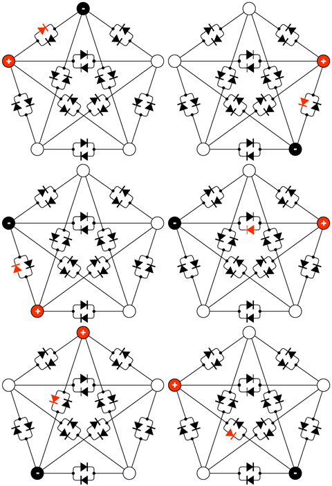
    Not every peripheral is equal, so I opted to prioritize the most important ones first.  I figure the most  critical parts of this design will be the LEDs, cap touch, and OLED screen, with the IR TxD/RxD close behind.  With that in mind, I focused on the Charlieplexing of the LEDs next.  This constituted a jump up in complexity by an order of magnitude or two since this is now leveraging the advanced features of the RP2350.

    The processor is equipped with 3 PIO banks (with 4 state machines each - the 4 state machines all share the same shared instructions, but have their own pointers) and 16 DMAs.  To run each bank of charlieplexed LEDs, I opted to use one PIO state machine and 2 DMAs.  One DMA loads commands into the PIO (which pins to input/output, which pins to drive high/low, and for how long), and one DMA does nothing more than restart the first DMA when it finishes.  The DMAs do have a ring-buffer feature, but that requires the list of transactions be an clean power of 2 (48 LEDs would need some padding to fit in 64 instructions).  But more importantly, to avoid shearing, I want to load in a new series of LED commands only at the exact moment the complete set finishes, and I'd prefer not to have to rely on an IRQ interrupt.

    There's a good talk here about driving LEDs with PWM.  My main takeaway from that is the human eye response is logarithmic, and an easy way to implement that on the hardware side is to square the brightness of each LED.  So while the software may command, as an example, an 8-bit brightness of 100 (out of the max 255), under the hood 100*100 = 10'000 is used for the duration that LED is ON for (out of the max 256*256-1= 65535).

    If all 48 LEDs in a bank are driven at the max brightness of 255*255, that's 48*255*255 clock cycles, at 150 MHz = 20 ms.  I'm targeting a 60 FPS system (16.6 ms), and rather than possibly skipping every 5th LED bank update (due to timing async updates between the core0 running py at 60 FPS, and the core1 pushing the updates to the LEDs when they're ready), I scaled down the max brightness by 20%.  So in the C code you'll see brightness*brightness*4/5;

    It's also important to note that if you drive one LED at brightness 100, that should look different than driving it at brightness 255.  However, if you do nothing but loop around the LED instructions for driving one LED, that becomes: turn LED ON, wait for 100*100*4/5, turn LED OFF, turn LED ON, wait 100*100*4/5..., which for all intents and purposes is identical to the 255 case: turn LED ON, wait 255*255*4/5, turn LED OFF, turn LED ON, wait 255*255*4/5.  What is needed is a pad time so that the 255 LED can remain on continuously, but in the 100 case, the pad fills a period of time with no light, effectively stabilizing the brightness of the entire bank of LEDs.  LED commands to the PIO are 16-bit duration, 8-bit output/input direction, and 8-bit output high/low.  However, if all the pins are disabled in a PIO command, the state machine interprets this as an extra long delay, in effect: 24-bits delay, and 8 bits of 0s.

    There is some trickery that can be done with how the pad delay time is calculated.  The simplest approach is to take the number of LEDs and multiple by the max brightness any LED can have: 48*255*255*4/5.  However, this can lead to a dim display if the LEDs aren't being driven at max - ex it's common to fade from one LED color to another.  So for this I compute an "effective led count".  For example I might set an effective LED count of 1, even tough I have two LEDs: one at 100 and one at 155.  The pad time becomes: 1*255*255*4/5 - (100*100*4/5 + 155*155*4/5) = 24800.  The take-away is: count the max number of LEDs you plan to have ON during an animation and set that as the effective LED count.  If the display is too bright, increase the effective...

    Read more »

  • Prototype r1 - Startup

    Parallel Logic06/21/2026 at 17:09 0 comments

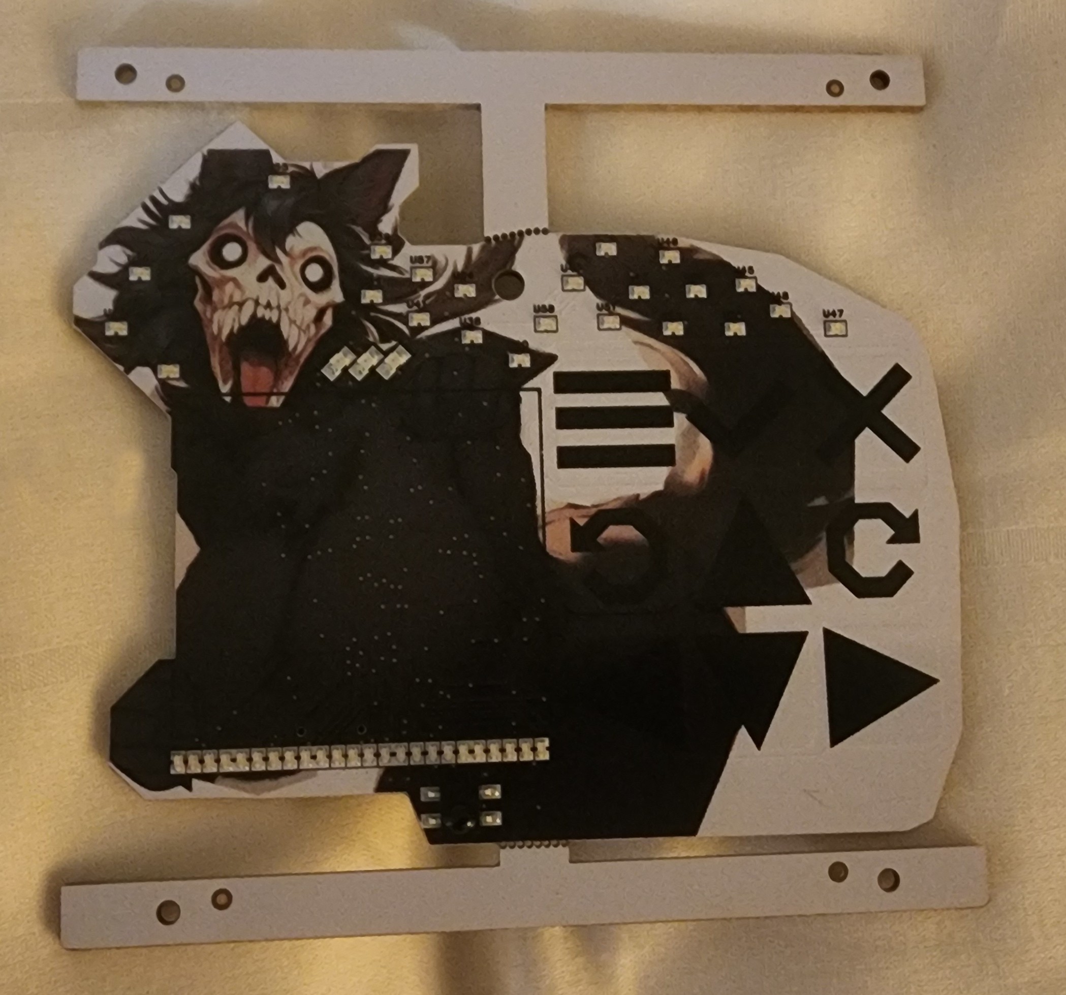
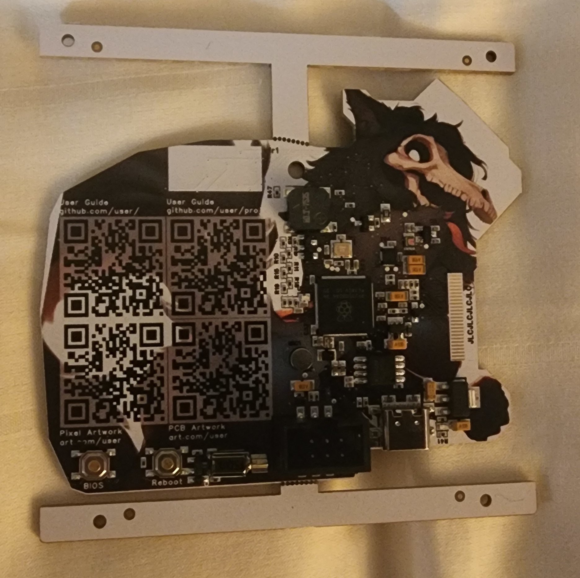
    First action when receiving new boards is to photograph them:

    One detail that irks me is the small white pull-back around every pad.  That's a property of the color silkscreen technology, but it's not something you see in the CAD render and does hide/obscure the artwork a little.

    I didn't take any effort to remove the black silkscreen, so you can see the reference designators around the entire back side, particularly over the white background

    A small note: the fab house has a minimum order of 5 PCBs, but I chose to only have 4 populated with parts - that gives me a clean copy of just the PCB itself that I can check continuity on the traces (workmanship) independent of the parts themselves (ex, a chip may internally close the connection between two VCC pads, where the PCB may have otherwise treated them independently).

    First power-ON is the most nerve-racking part of the process in my experience: either the board works fully or it doesn't - it's a very binary fork in the road.  It's normally worth taking this step very slowly - I have spare populated prototypes, yes, but those are really for backup/experiments during development).

    - Did a resistance check between power (3v3) and ground.  Got 600 ohms.  Not terribly insightful aside from there at least shouldn't be a dead short between power and ground, so that's good enough to proceed.

    - Observed that there is a mechanical interference between the screen and the edge of the PCB (her hand holding the screen).  I had specifically planned around this, but still ended up with interference - turns out misread the screen mechanical drawing and though the cable was much longer than it ended up being, so definitely a fix for the next prototype... I later used a dremmel to shave off that part of the PCB so I could assemble the screen properly.

    - I applied 3.3V with a 100 mA OCP limit on my power supply, with the thought that if this design was defective, it should hopefully not draw so much power that it destroys itself- trying to preserve the prototypes as long as I can

    - The 3.3V power indicator LED came ON (much brighter than I expected, will be decreasing the 1~5mA current draw notably on that LED in the next prototype). Power draw is around 100 mA, where is all that power going...

    - Poking my finger around on the PCB to try to find the hot spot, I misdiagnosed the problem as coming from the crystal, and I went down a rabbit hole trying to debug that.  In the coming weeks, I would determine it was the neighboring IMU where I swapped the interrupt and VCC pins, putting it in a half-driven configuration that loosely shorted power to ground and drawing excessive power.  There is an option to de-solder one part and observe the impact on the power draw that way to definitely prove where the issue is coming from, but I didn't pursue that path here, in part because this is a 2-sided PCB design and makes it hard to rest the board on a hot plate and not inadvertently remove part from both side of the PCB.

    - But pushing forward, can it be programmed despite the high power draw?  Plugging in via USB in BOOTSEL mode and it successfully manifests as a USB drive just like the pico2 (I was using this for software development up to this point), so far so good.  Uploaded a simple blink sketch (driving the debug LEDs), and nothing...

    - However, adding in Serial printout works normally, so the chip is running the bit file, but not driving the LEDs... issue was the pico2 is a RP2350A chip, and in order to program the larger (more pins) chip, you need one that enables the extra GPIOs.  When I set the Arduino IDE to MyMakers RP2350B, that enabled the extra pins, including the LEDs on the upper bank, and the debug LED blinked.

    The objective now is to test each sensor/peripheral to a bare minimum degree necessary to make a go/no-go determination to move forward.  Simplest one after the...

    Read more »

  • Prototype r1 Design

    Parallel Logic06/20/2026 at 05:00 0 comments

    One of the very first risk-reduction activities I did was to inspect how difficult it is to run Python on the Pico2 (RP2350A with 4MB Flash), running across the dual cores.  Findings:

    - Core0 executes MicroPython out of Flash, which means core1 doesn't have Flash access.  Any data that core1 operates on needs to comes from shared memory between core0 and core1 (there is also a FIFO that raises IRQ events, but that's more for flagging transfers than to actually bulk-transfer data)

    - I'm not entirely clear how much of a performance hit running Python on a core is vs running C.  I opted for C++ code on Core1, accessible as a library in Python in core0.  This allowed me to prototype the C code portion standalone in the Arduino IDE (this is the contents of the src/experimentation/ folder)

    - The original vision was to have core0 perform administrative functions "draw a rectangle here" and core1 would perform them "pixels x-y in this list are now this value, 'for' loop runs...".  Core1 would also handle all the peripherals.

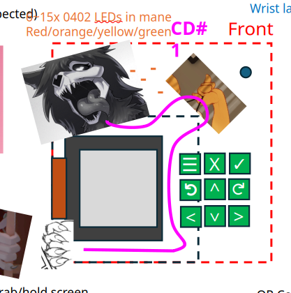
    First concept layout

    - I had early notions of a leash of LEDs going from her neck all the way around the screen.  Later, when I laid this out to scale, the cap touch buttons needed to be so large, there wasn't good clearance between the touch pads on the right and the screen on the left (plus I has EMI/EMC concerns between the sensitive cap touch pads and the high frequency charlieplexed LEDs), so I ultimately broke this string of LEDs into two banks: one in her hair, and one as a kind of status/scroll bar below the screen - giving the cap touch pads a clan shot directly into the processor (where I'm trying to measure capacitance changes on the order of 10s of pF).

    - I opted for red-green LEDs, on the premise the primary color of SCP content is a shade of orange (mix of green and red).  Chareliplexing N pins allows control of N*(N-1) LEDs - ex for 8 pins that's 56 LED elements.  The width of the screen fit around 24 LEDs (24 red-green LEDs is 48 LED elements).  So I moved forward with a lower bank of 24 red-green LEDs below the screen, and an upper bank of also 24 LEDs.  This allowed me to recycle the same PIO/code interface between the LED banks.

    - I considered WS2812 LEDs to get full RGB support (also called "NeoPixel"s by Adafruit).  The SAO standard stipulates 3.3V input, and I disliked the idea of needing to add a 5V step-up converter required by the WS2812s.  I wanted to keep the BOM cost reasonable, so opted for dumb LEDs (with a 1.8~2.3V forward voltage) with a plan to Charlieplex them (requires floating most of the GPIO pins in a bank, and then driving one pin high, one pin low, holding that for a tiny fraction of a second, then moving on to the next pairing).  The RP2350 supports floating the pins through PIO, where the prior generation chip did not.  The impact of chareliplexing LEDs vs a serial string of WS2812 is that it notably complicates PCB layout since there is now a direct electrical connection from LED directly to the processor (vs just a chain connection to each LED's neighbor in WS2812).


    - Those reviewing this closely will note the processor runs at nominally 3.3V (per the SAO standard), but the green LEDs wants ~2.9V and the red ~2.1V.  There is a dirty trick where high current draw (~20mA) through the processor will actually drop the drive voltage a bit, so I actually drive the green LEDs straight off the RP2350 GPIO pins.  For the red, I did include a resistor dropper, but I kept it to only 3 resistors total across the entire bank of 8 GPIO pins.  I did this by carefully selecting grouping of red LEDs to all share a common pin and routed the red connections through the resistor before reaching that gpio pin.

    - All this work was done before the DEFCON34 MICD was released.  At this stage, I was very concerned about overall size and keep-out zones....
    Read more »

  • Getting Started - Project Formulation

    Parallel Logic06/18/2026 at 07:56 0 comments

    The idea for this project came together while walking around Supercon 2025 and combining several factors:

    - I made made an SAO design for DEFCON31.  I had a base design that could be customized with a sticker. One lesson learned was that scrounging through a bag to find the exact right sticker the customer wanted was time-consuming.  Rather than many products offered at a single price point, it's better to diversify the product offering across price points, or just offer a single configuration of the product.  Also, the dark/broody design sold the best (and incidentally was the one I made the least copies of and sold out first).

    - DEFCON is themed around skulls and hacking

    - If centering the design around a character, it would be advantageous to avoid copyright (ie. open source character), but still have something recognizable.  This being for DEFCON34, could have a tie in with rule34... (but still keep the hardware and software design formally SFW)

    - A rock-paper-scissors type interaction is very effective as an ice breaker, but lacks motivation to continue talking with the person after the first interaction.  Want something with more staying power, like a chat bot that is broadcasting messages/replies - so the longer you talk with someone (assuming both have this SAO), the more of their messages you pickup, and maybe unlock perks in the SAO... (FYI, laser tag has been done)

    - Have had requests in the past to make the SAO hackable, so want something modern running at least some Python, so thinking RP2040 or ESP32 product line for good community support.  Went with RP2350B and 16MB external Flash.

    - I've had trouble conveying information (game/menu state) to users with LEDs alone, so want to include a proper screen in this design so information is all presented in one place.

    - I wanted to do capacitive touch buttons since they are the lowest profile option and feel better (imho) than traditional clicky buttons.  ESP32 has a built-in controller for this, but the RP2 series does not.  So doing capacitive touch on the RP2 series will be a gamble/risk...  Since most are right handed, would have the buttons on the right, and the screen to the left.