-
Omnipolar hall sensor is good!
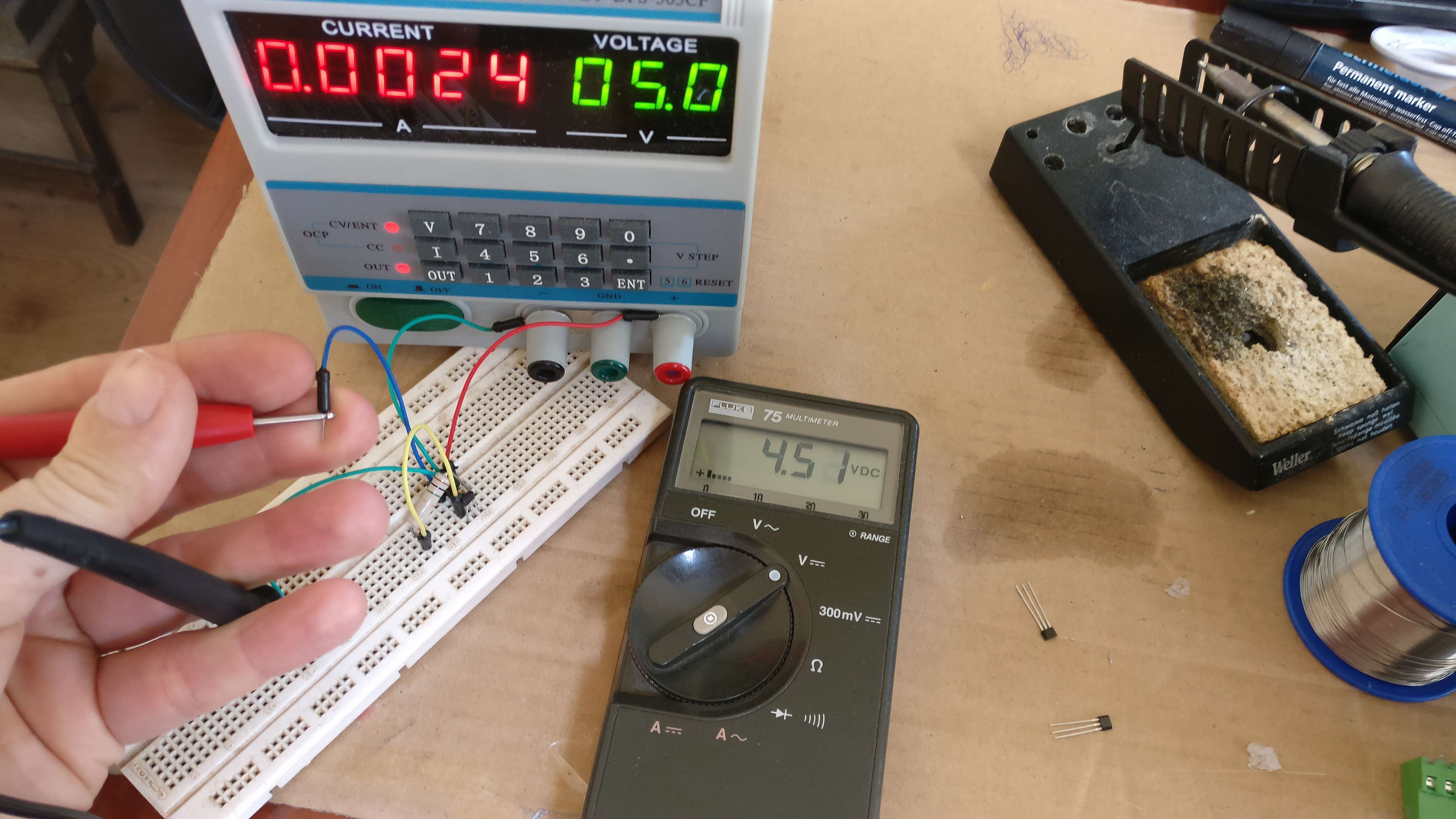
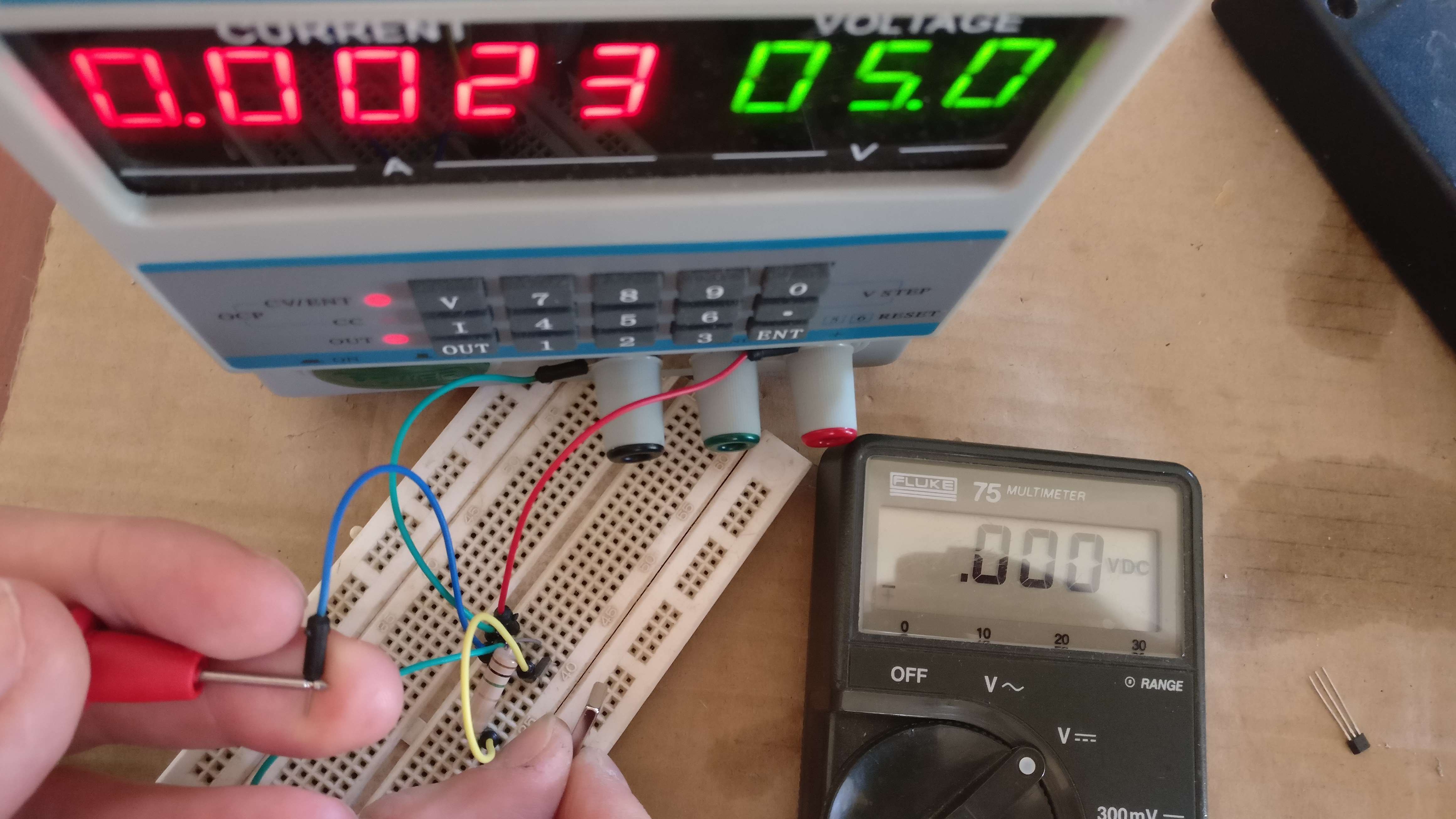
05/15/2017 at 11:33 • 0 commentsI had a problem with the latching hall sensors last friday. Today I got the omnipolar hall sensors from Farnell. And these sensors work as it should. So I will use these sensors in my door and windows frames. The output is high when no magnet is detected and is low when a magnetic field is present. I have used a high pull-up resistor (1M ohm), so the high level is only 4.5V.
![]()
![]()
-
Door/window sensor
05/12/2017 at 11:52 • 0 comments![]()
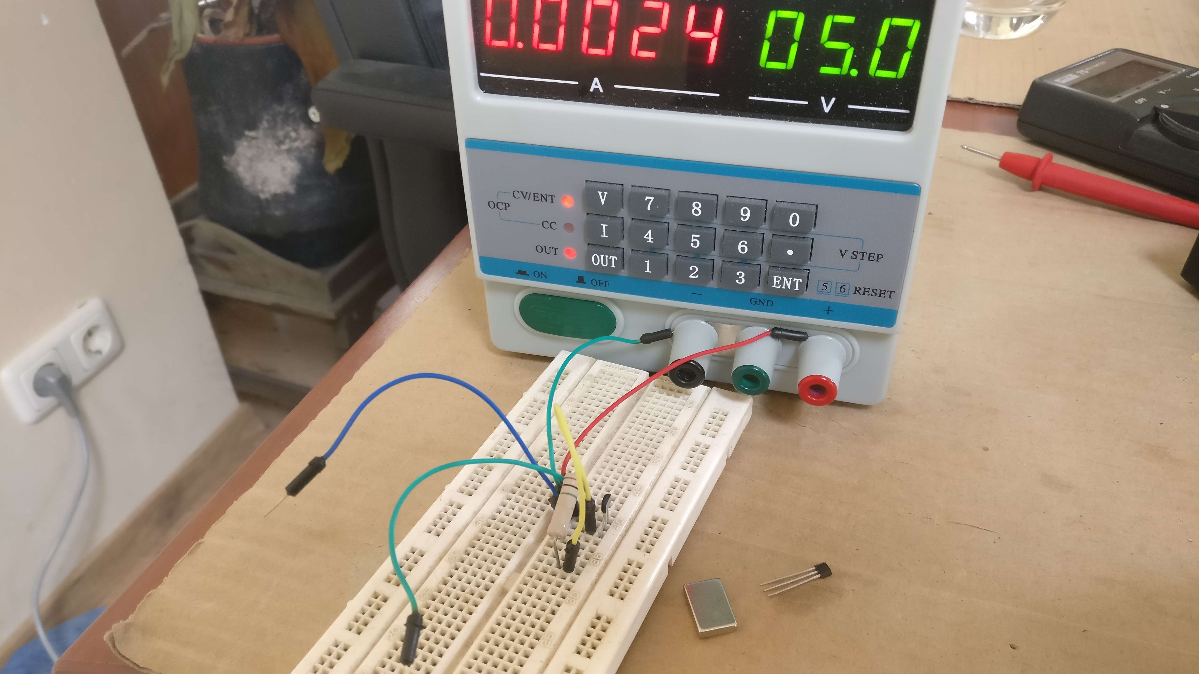
How does the door/window sensor work? I will place a small magnet in the door/window (has to be painted again, so it doesn't matter) and a hall sensor in the frame of the door/window.
Today I got my hall sensors from Farnell. Yesterday I was in a hurry and just ordered a few hall sensors (in TO92 housing). What can go wrong? Well, the hall sensor I ordered can not be used as a door/window sensor. The sensor I ordered is bipolar. The output is set when a S field is applied and reset when a N field is applied. The state of the output is maintained when there is no magnetic field present. I need a sensor that has an active output when a magnetic field is present (so a S or N magnetic field when the door/windows is closed) and the output is not active when no field is present(door/window is open). This means I need an omnipolar hall sensor for the door and window sensors. The output becomes active (this means low because of the open colector output) when a magnetic field is present. On monday I will receive the omnipolar sensors....To be continued.
-
Sensors for the extension PCB
05/06/2017 at 13:12 • 0 commentsI will add the posibility for a KNX TP-UART2. If I don't have enough sercoms on my Atmel device, I will use zero ohm resistors to enable the KNX uart OR another function.
When I finish this project, I will have some very nice sensors that I will modify:
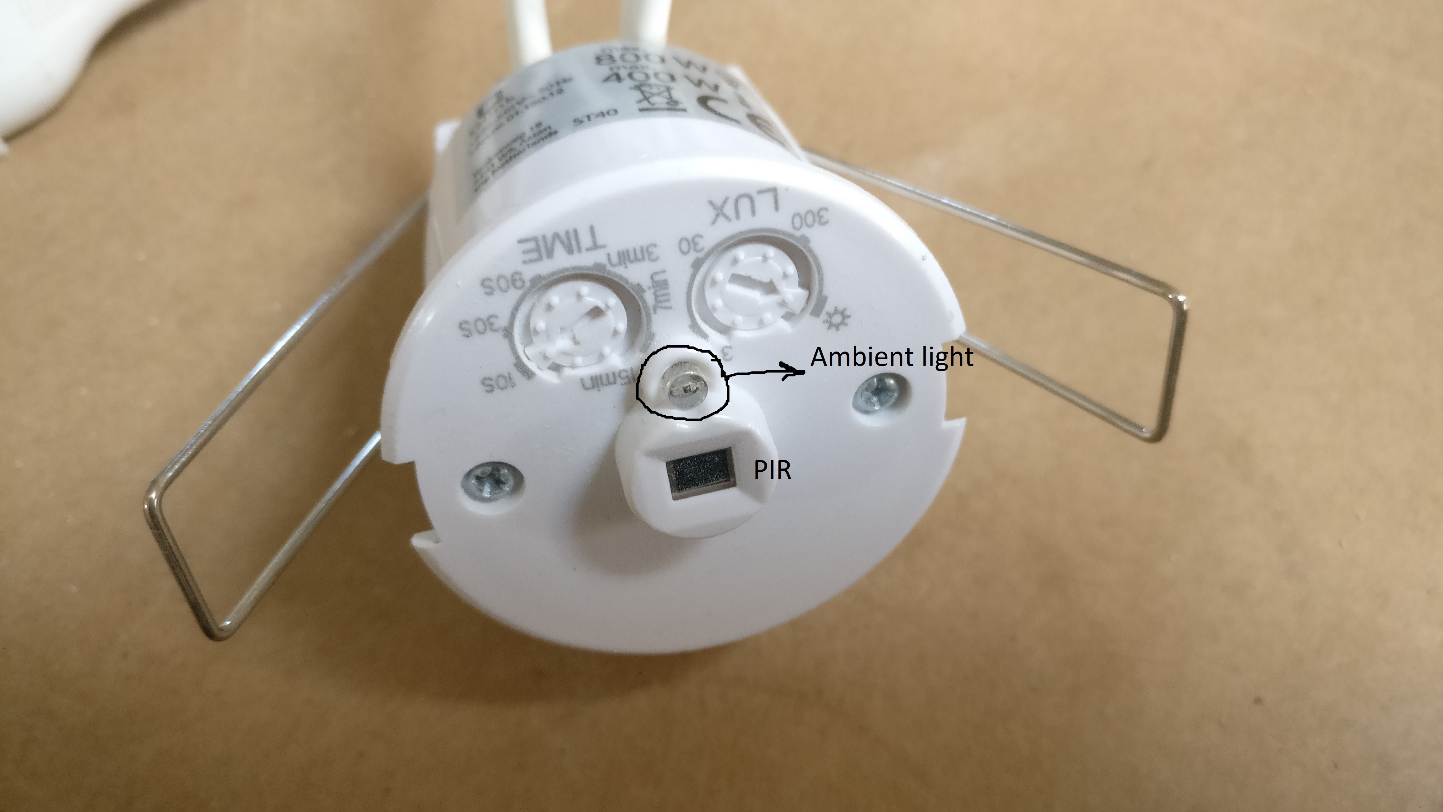
* PIR with separate Ambient light output and PIR sensor output. I have bought a cheap PIR from hornbach (12Eur, Q-link Wall mount sensor.). This pir is a ceiling pir for a round mounting hole in the ceiling. Just like a ceiling spot light. I will modify this PIR to have 2 separate digital outputs. 1 open collector digital output for the ambient light strength (PIR unit will handle the Lux threshold) and the other open collector digital output is for the PIR sensor. Separation enables me to switch the light with the Loxone when it's dark, but it will also enable me to use this PIR unit to enable the alarm (also when it's light, so during the day).
![]()
* CO2 sensor. I have found a cheap CO2 sensor on aliexpress. I will also use this sensor in my livingroom and bedroom to maintain a healthy climate in those rooms. It will switch the perilex socket of the Heat recovery ventilation (HRV). A humidity sensor will be used in my bathroom. https://www.aliexpress.com/item/MH-Z19-NDIR-CO2-Sensor-Module-0-5000ppm-new-and-original-in-stock-free-shipping/32697750985.html
* Windows/door sensor. For the windows and some doors I will not use a reed-relay, but probably a hall sensor with small PCB to make a open collector output. https://www.aliexpress.com/item/50-pcs-SS41F-41F-0H41-SH41-S41-Bipolar-Hall-Effect-Position-Sensors-SIP-3/1903012341.html
Most of these sensors will be handled after this extension PCB. Some of these sensors will be developed in parallel to this project.
PS. why am I not using reed relay and a normal relay? I want to use hall sensors and SSR because these semiconductor parts have no mechanical parts that can wear down. I want to make the system durable.
-
Dali?
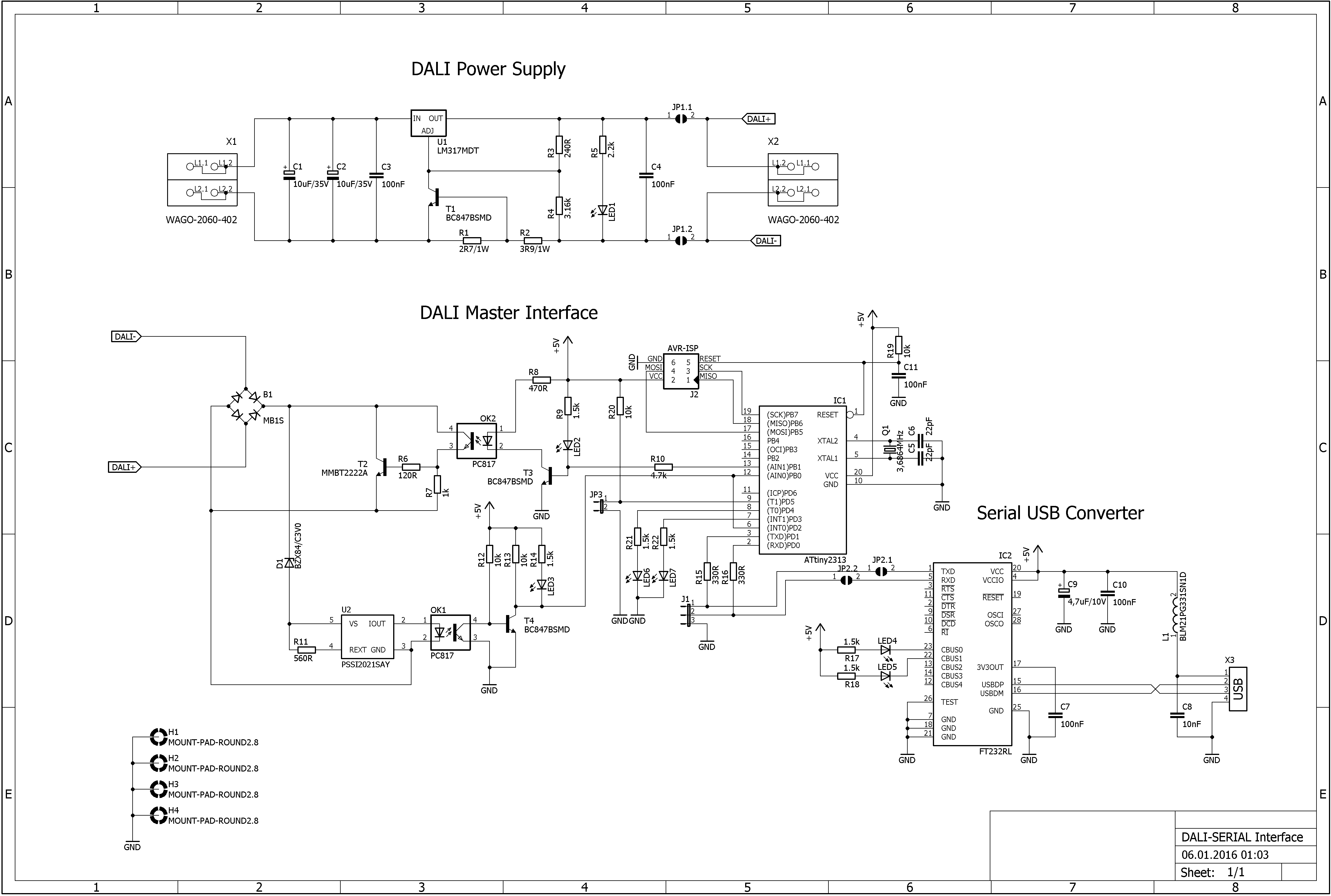
05/04/2017 at 15:36 • 0 commentsIt's also possible to add Dali, but too many interfaces seems overkill. Software for Dali can be found here: http://blog.perquin.com/blog/arduino-dali-interface/
This is the schematic that I can implement :
![]()
-
Arduino Modbus and KNX software & hardware
05/03/2017 at 09:11 • 0 commentsSome software links for this project....
* Modbus TCP. http://myarduinoprojects.com/modbus.html
* Modbus master. https://github.com/4-20ma/ModbusMaster
* KNX TP uart and libraries. https://bitbucket.org/dka/arduino-tpuart http://www.opternus.com/de/siemens/knx-chipset/knx-transceiver-ics-tp-uart-fze1066.html http://liwan.fr/KnxWithArduino/
* KNX TP UART chipsets. http://www.opternus.com/en/siemens/knx-chipset.html
* 1 wire software for the DS2484. https://github.com/ianmetcalf/arduino_libraries/tree/master/DS2482
-
The status of the project....so far.
05/02/2017 at 19:25 • 0 commentsIt has been quiet for some time, but I have made some progress. This is the current status of project. I am making the schematics in Altium designer. These are the features I will add to the project:
* main controller is the ATSAMD21G18A-AUT. I want to make the schematic Arduino M0/Arduino zero compatible. Controller and SWD connections have been drawn (controller is now in PCB library).
* 64 IO's with IO expanders. I can make them with 3v3 or 5v level output. I chose for the 5v level for a better robustness against interference. The IO's are expanded by PCAL6416APW,118 IO expanders (16 IO's). These expanders can also generate an interrupt when an input changes and can therefore react very fast when a button is pushed. I have 64 IO's, so this means 4 expanders. There is only 1 addr line on the I2C device, so actually I can only have 2 expanders on 1 I2C bus. I solved this by using the 4053 that switches between I2C-group1 (expanders 1 and 2) and I2C-group2 (expanders 3 and 4). The IO's are NOT protected against 220VAC or 24VDC, but have a normal ESD protection. These digital IO's can be connected to a relais board or SSR board (I will make this board afterwards). The inputs can be connected to an optocoupler board to separate the safe electric zone of the IO expander with the unsafe zone, but you can also switch the 5V directly with the momentary switches from the outside (less safe). The IO expander schematic is finished. I use 1 sercom for this I2C connection and the I2C from this sercom is only for the expenders.
* Ethernet. The ethernet connection is provided by the ENC28J60 board from aliexpress. Cheap and fully functional. I have to add this to the schematic
* RS485/Modbus/DMX. Since we have ethernet, it may be possible to make an ethernet to MODBUS and/or DMX interface. I have added 2 RS485 connections. One for the Modbus and the other for the DMX bus. The RS485 will be half duplex and will be connected to 2 sercom uart interfaces. The RS485 interface IC's are the MAX485CSA or the ST1480ACDR. I have already added this to the schematic.
* 1-wire. I will also add a DS2484R+T device. This is an I2C to 1 wire interface. Most home automation systems have the DS18S20 thermometer sensors to measure the temperature. This will also be possible with our device. I2C will be connected to a sercom. I can optionally add an I2C graphic LCD. Please leave a comment if you think this is useful. I have only drawn the D2484 in the library.
* KNX. I wanted to add KNX to this device. But it doesn't make sense to address KNX devices from this device (since the Loxone can do that) and I think the main connection to the outside will be TCPIP, so making the KNX device connection to the Loxone will also not be an option. Please leave a comment if you think it is useful that this device will functions as a KNX device. It's also more expensive due to the software stack. No KNX connection is present in the current schematic.
* Wifi. I will use ethernet, but I think that many people want Wifi on this device. I chose for the 'old' ESP8266 and not the ESP32 (with BLE). I will add the ESP12 module. I have added this to the schematic.
* USB. I want to make board with the ATSAMD21 arduino M0 compatible, but I don't know if we need an host USB connection. It's a small effort to make it possible to make this connector host capable, but then I have to use micro USB. I prefer the good old USB B connector to make the connector more tough. This means the ATSAMD21 will only be an USB device. Do you use the host function?
* Power. DC-DC synchronous switches will convert 24VDC to 5VDC and 3V3. This has not been implemented yet.
Schematics will be shown here on a short notice.
Just a question....I have muliple functions added to this PCB. It will have an ethernet to 1-wire function, ethernet to Modbus, ethernet to DMX and ethernet to IO function. Is it possible to have all these function with 1 ethernet connection?
Cheap Ethernet IO extension board for smarthome
Cheap low power smarthome extension board with Ethernet/Modbus/1-wire/DMX512/Wifi connection