Vlad
Vlad-
HDMI/DVI: TFP410
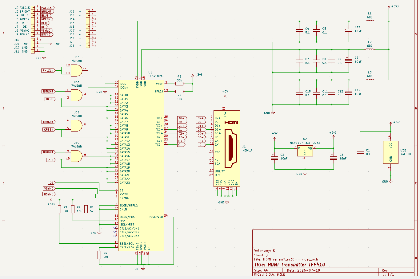
07/19/2026 at 17:49 • 0 commentsFinally, at least for now, I've decided to go with TFP410. It is exactly what is needed for my task to translate video output BRGB+HSYNC+VSYNC into TMDS for DVI-digital. The circuit diagram I created for an adapter board:
![]()
The AND-gates will be 74LVC08. I didn't found this symbol in KiCAD but it is not a problem. I will also need to generate pixel clock signal 27MHz and Data Enable signal in my rp2350b ULA firmware but is not an issue too because I have 2 additional GPIOs available that were initially planned specifically for HDMI output support.
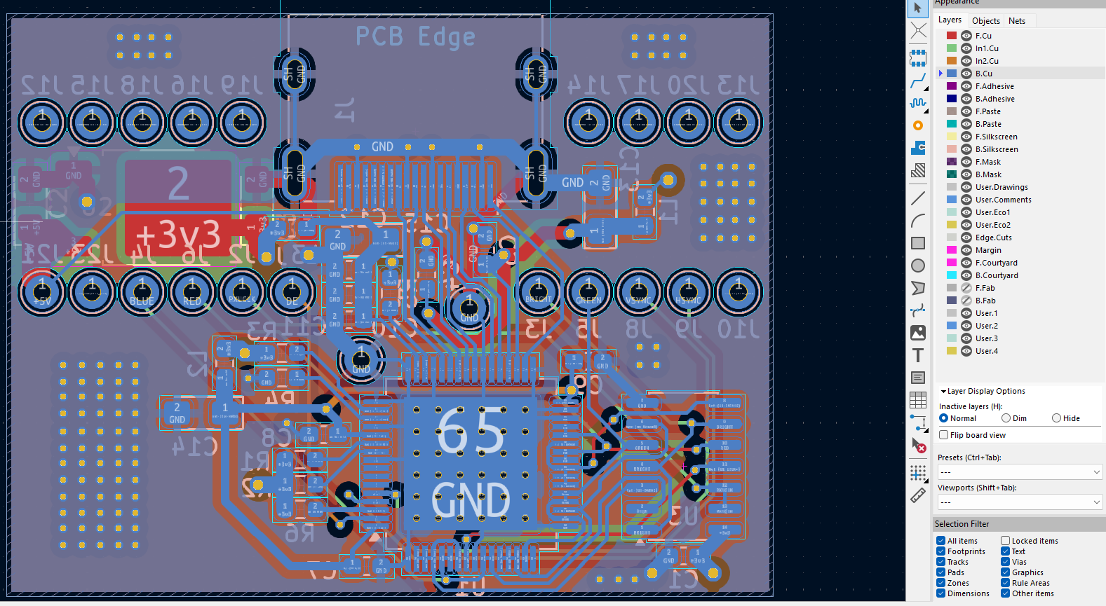
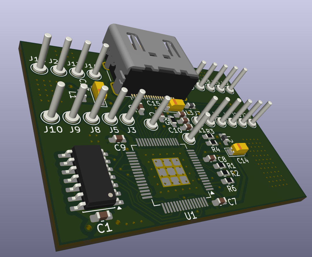
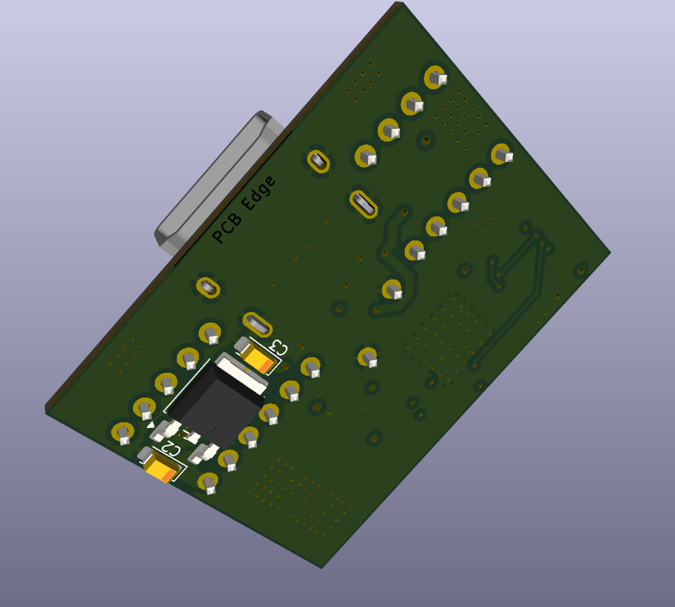
Current PCB design:
![]()
![]()
![]()
A real challenge will be soldering of TQFP-64 chip with my hand solderer manually.
-
HDMI - another idea
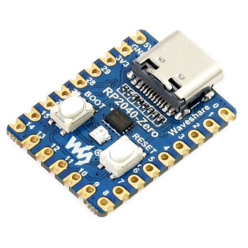
07/15/2026 at 15:16 • 0 commentsThanks to comments on Jenny's article, another idea came into my mind - VGA to HDMI adapter. I have digital RGB/Bright/VSYNC/HSYNC signals out from my "ULA" rp2350b and only need to translate them to TMDS. There are some specialized chips like tfp410 for this purpose but probably much easier would be using another Raspberry mcu and do it in software. Looks like something like rp2040-Zero must be good for this task:
![]()
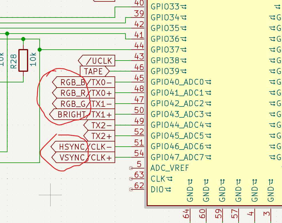
The task is to catch VGA output from "ULA" GPIOs:
![]()
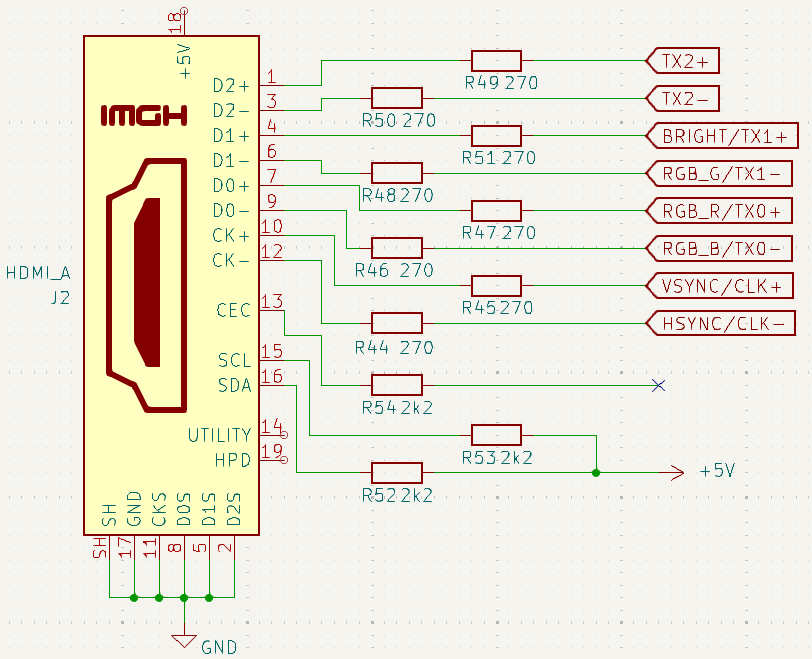
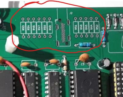
and translate them into TMDS for HDMI output. Looks like it should be possible to put the Zero board "instead" of resistors R49 - R51 on existing PCB:
![]()
![]()
The resistors still have to be installed somewhere though.
To be continued...
-
HDMI/DVI
07/11/2026 at 14:54 • 0 commentsWell, I investigated HDMI/DVI stuff a bit. For 720x576x50 progressive video mode, which works perfectly via analog VGA, the calculations doesn't look optimistic. Pixel rate in this mode is 27MHz which means bit rate 270MHz. To implement it in this project I have to do the following:
- Overclock rp2350b deep enough to handle 270MHz bit rate. It looks possible. At least there are a lot of projects doing this, especially for HDMI/DVI support.
- Recalculate some timings and delays in existing software. Not a big deal.
- Implement the functionality itself to support DVI. This is the challenge. However, there are successful implementations can be found in the net.
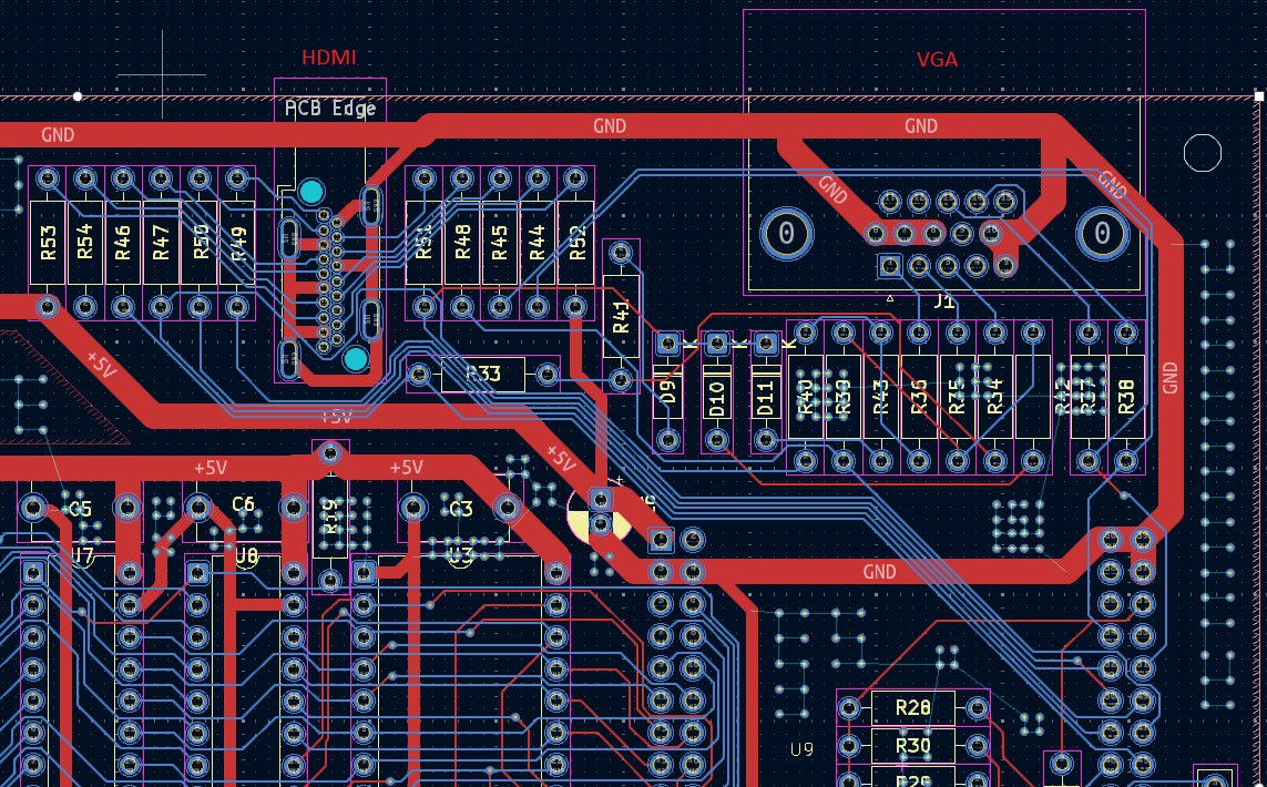
The real obstacle to move forward with this implementation is probably current PCB design. I'm not sure if it will work for 270MHz bit rate. First of all, rp2350b is located on WeAct board which connected to PCB with a connector. Then HDMI and VGA networks are messed up a bit on the PCB itself. Unfortunately, I didn't take into account DVI timings when designed the PCB.
![]()
For now it looks like there is no sense to even try implementing HDMI/DVI output with the current schematic and design.
-
Joystick adapter
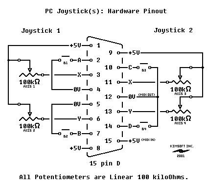
07/08/2026 at 16:23 • 0 commentsInitially I planned to find some cheap used joystick on flea market and just install switches instead of whatever it has on its axis to connect it as Sinclair joystick 1. But then I realized that there are still analog joysticks with DA-15 GamePort connector available even new on marketplaces so I found one for only $3.5. Ok, it took another $4 for delivery.. :)
These joysticks use analog potentiometers for X and Y axis and switches for buttons:
![]()
I decided to design an adapter to use the joystick as is and connect it as Kempson interface to appear on port 1Fh.
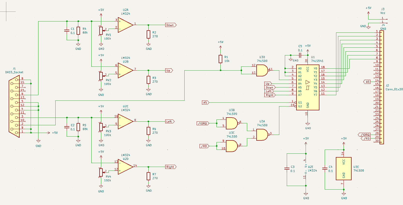
Circuit diagram of the adapter:
![]()
I used LM324 op-amp to translate analog potentiometers resistance to digital On/Off signal. Thresholds to switch Up/Down/Left/Right bits On or Off can be set using RV1 - RV4.
Button signal must be inverted so I used 74LS00 for all needed logic here. Another option would be using buffer with inverted outputs in place of 74LS541 and set up op-amps network accordingly. I guess it would be less natural so it doesn't worth it.
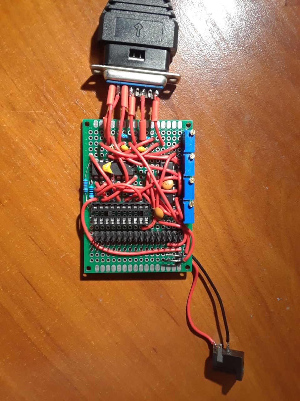
Prototype of the PCB:
![]()
KiCAD project includes PCB design. I'm continuing to use the prototype, it works perfectly.
Z80 + RP2350B ZX-compatible homebrew retrocomputer
ZX Spectrum-compatible homemade retrocomputer based on Z80 CPU + discrete RAM and ROM + Raspberry RP2350B as ULA/chipset