 George Conneely

I have a pretty varied stash of retro display equipment, mainly nixie tubes and wanted to make something a little different than another clock, as well as something actually useful. I like electronic projects, so I decided to make my own soldering fume extractor with a bit of an overengineered twist.
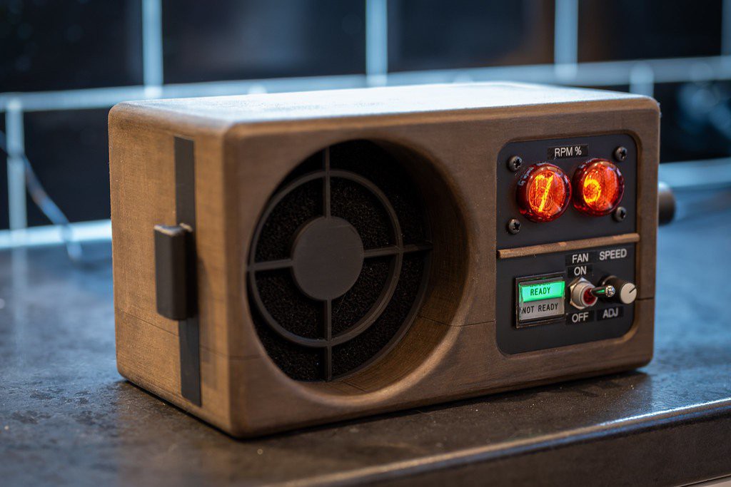
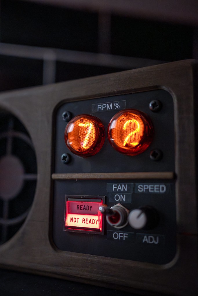
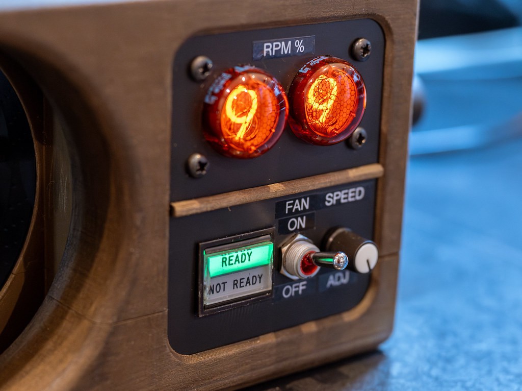
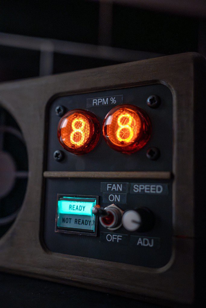
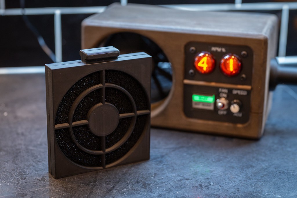
The extractor features two GN-4 nixie tubes which display fan RPM from 0-99%, and a "READY/NOT READY" indicator from the cockpit of an RAF Tornado fighter jet. The desired fan speed is set using the knob on the front panel. The ready/not ready indicator changes state depending on whether the actual speed is close enough to the desired speed. The fan can also be manually switched off with the satisfying metal switch. The fan is a 120mm Noctua industrial PWM fan, with a slide out charcoal filter fitted in front of it to keep the exhaust air somewhat clean.
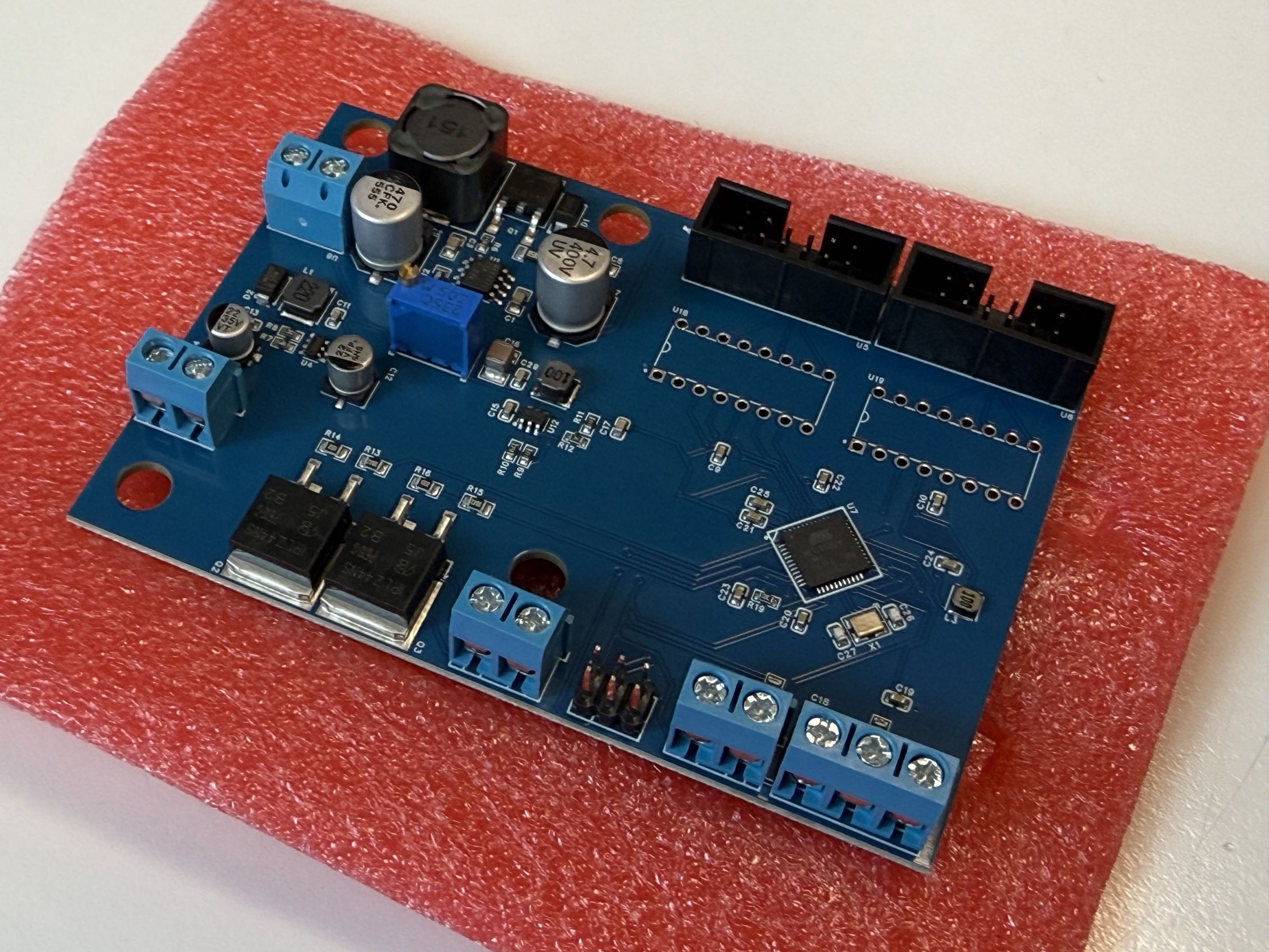
I made a custom PCB to control the fan,tubes and indicators. Simply put, it's an ATMega microcontroller linked to two K155ID1 Nixie drivers, two IRLZ44N MOSFETs for the ready/Not ready indicator and the tach/PWM signal lines for the fan to report/control its speed to the microcontroller.
The PCB also uses two simple DC-DC boost converters to power 170V to the nixie tubes, and 24V to the ready/not ready indicator. I used EasyEDA pro for the PCB design and JLCPCB to manufacturer the boards.
The enclosure is 3D printed in PLA Wood, which I sanded down and then stained with wood dye to give a natural look. There is a removable cartridge containing a charcoal filter to keep the exhaust fumes relatively clean.
Hopefully I've went into enough detail on this project without rambling on too much. Enjoy the pictures!
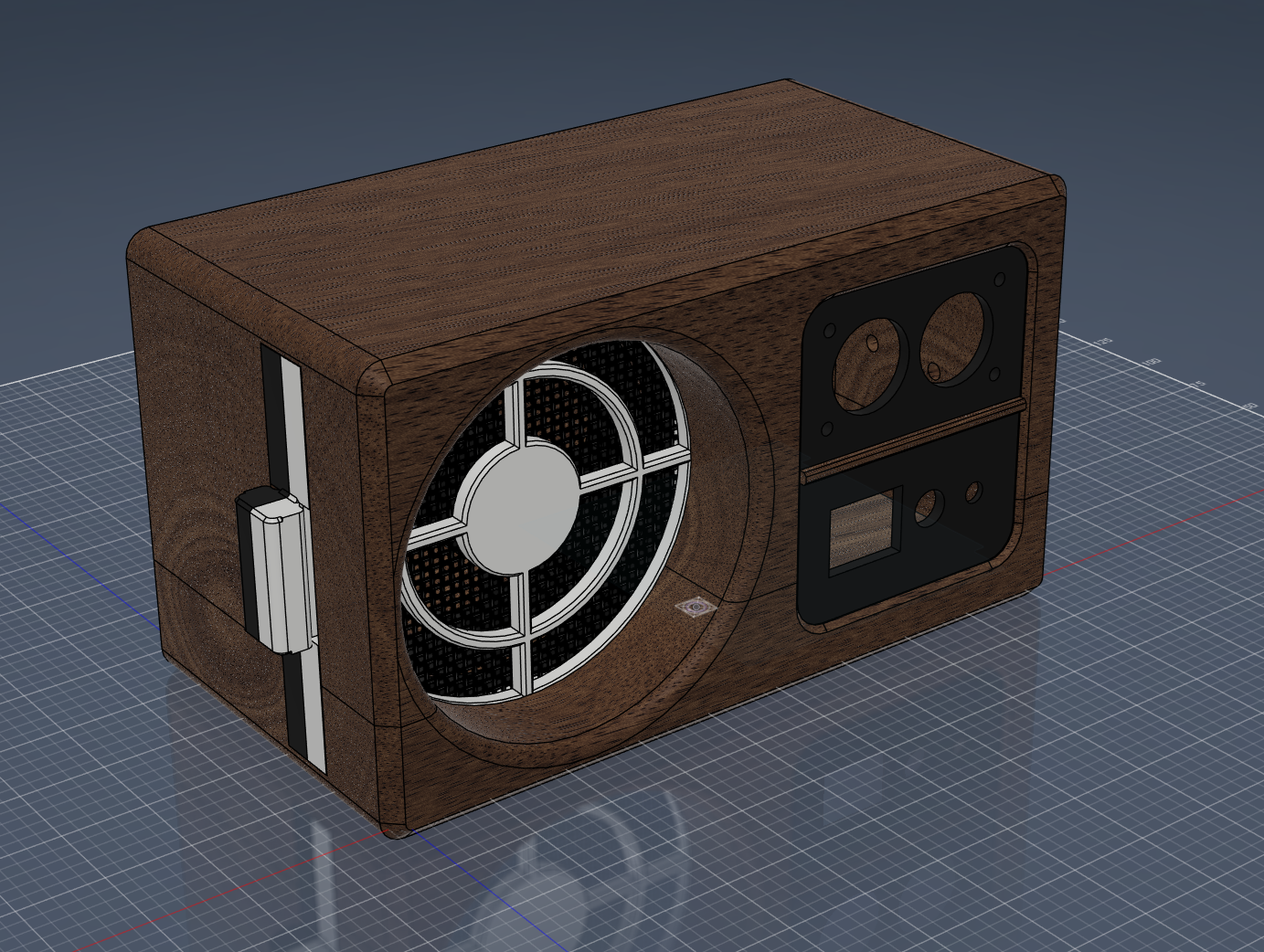
A general overview of the enclosure in Fusion360.
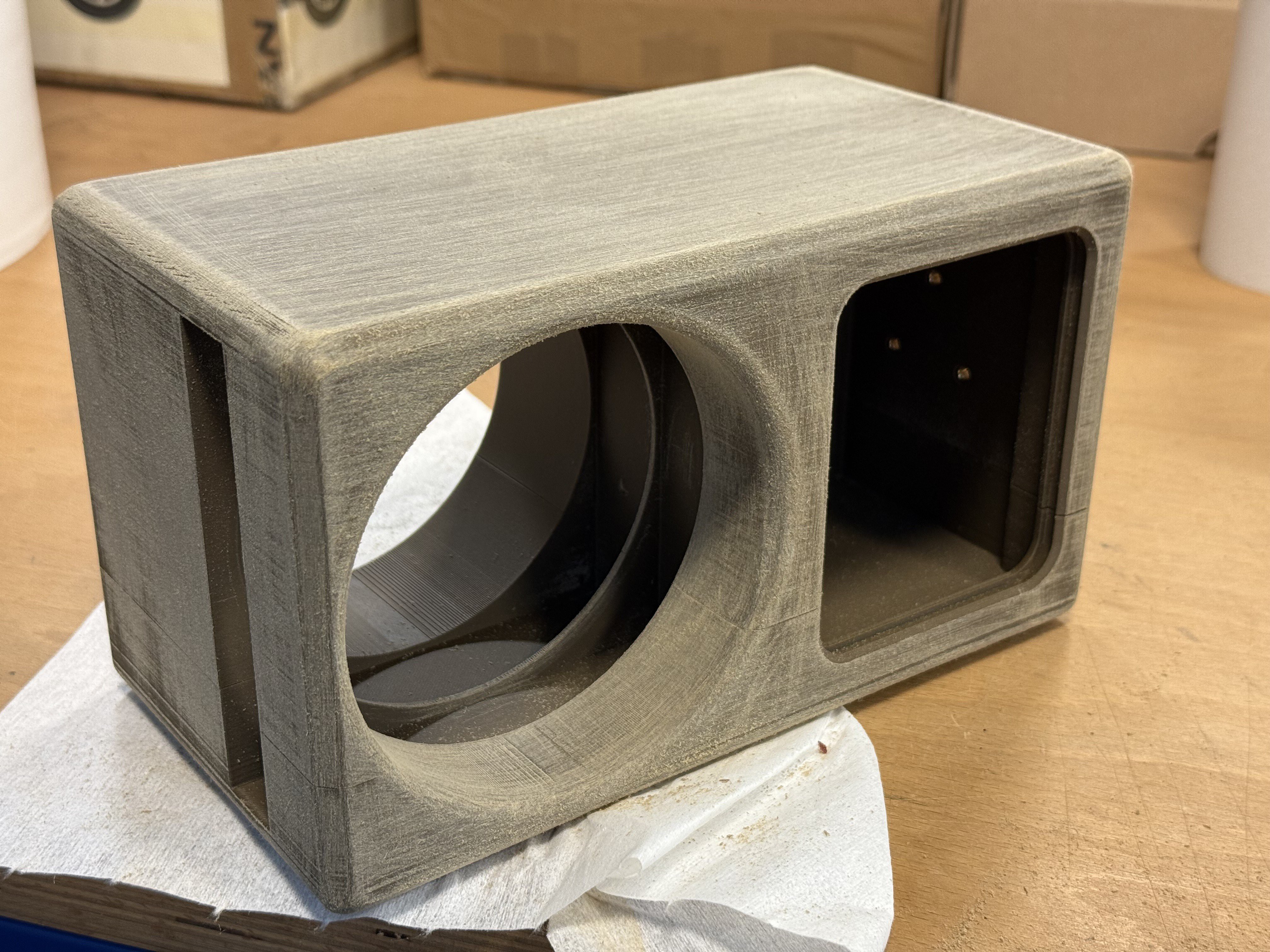
Enclosure bolted together and sanded down prior to staining with wood oil.
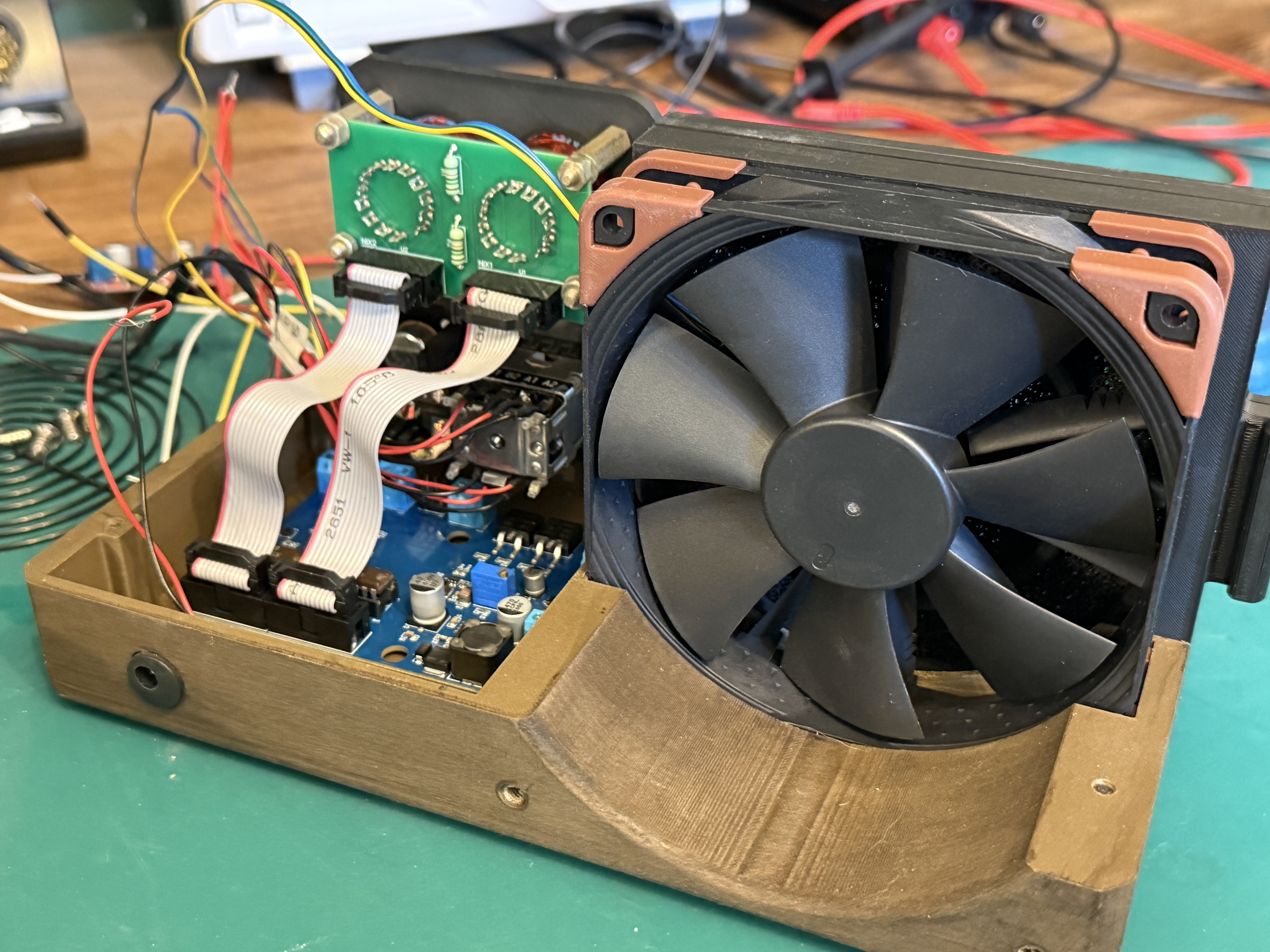
Somewhat of an idea of how everything fits (crams) together inside.
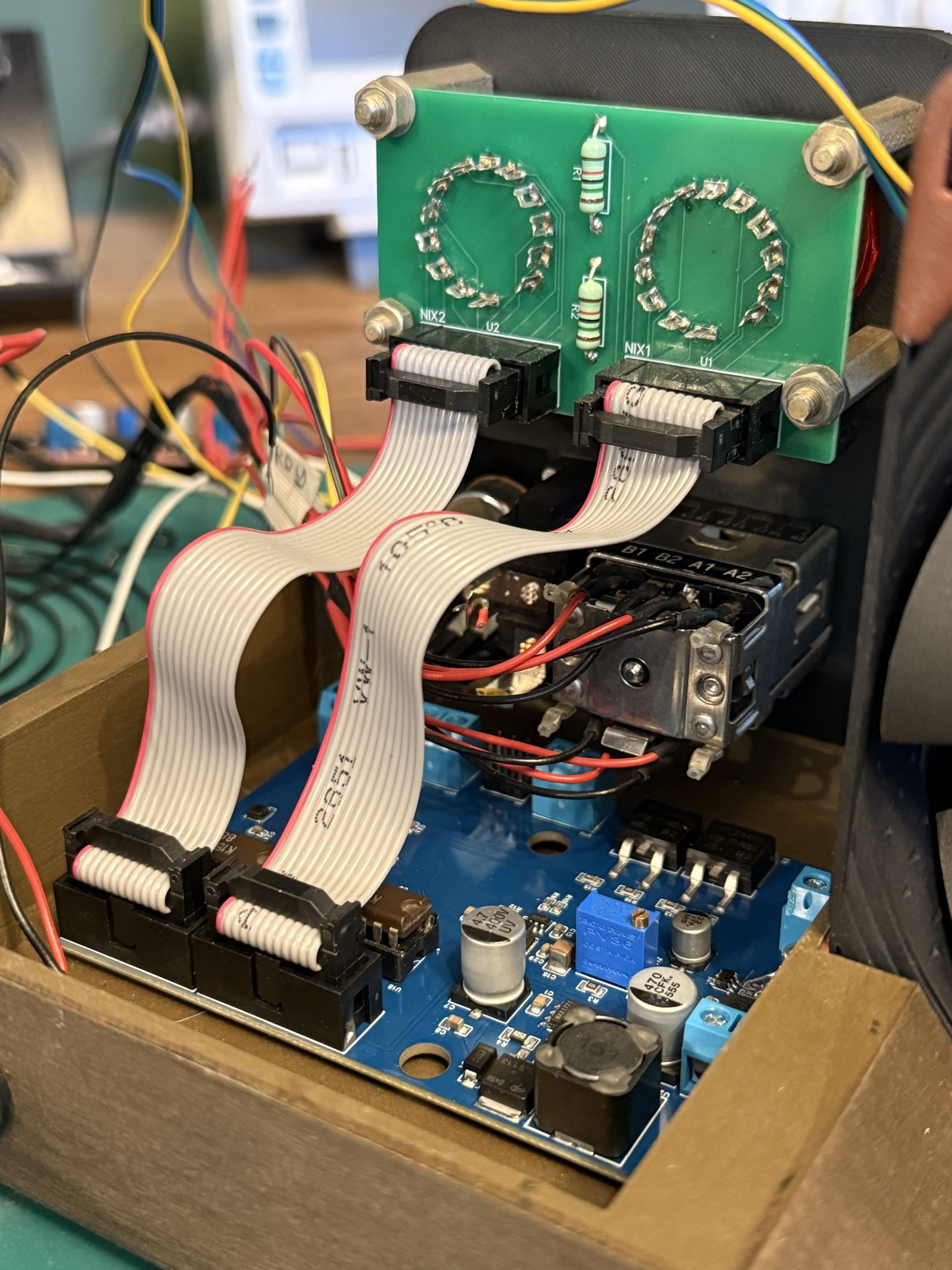
The PCB (without K155ID1 drivers fitted). I'm still figuring out the world of efficient PCB design. If I were to make this again it would be laid out and routed a little differently.
This project really driven home the lesson on how important adding decoupling capacitors practically everywhere is.
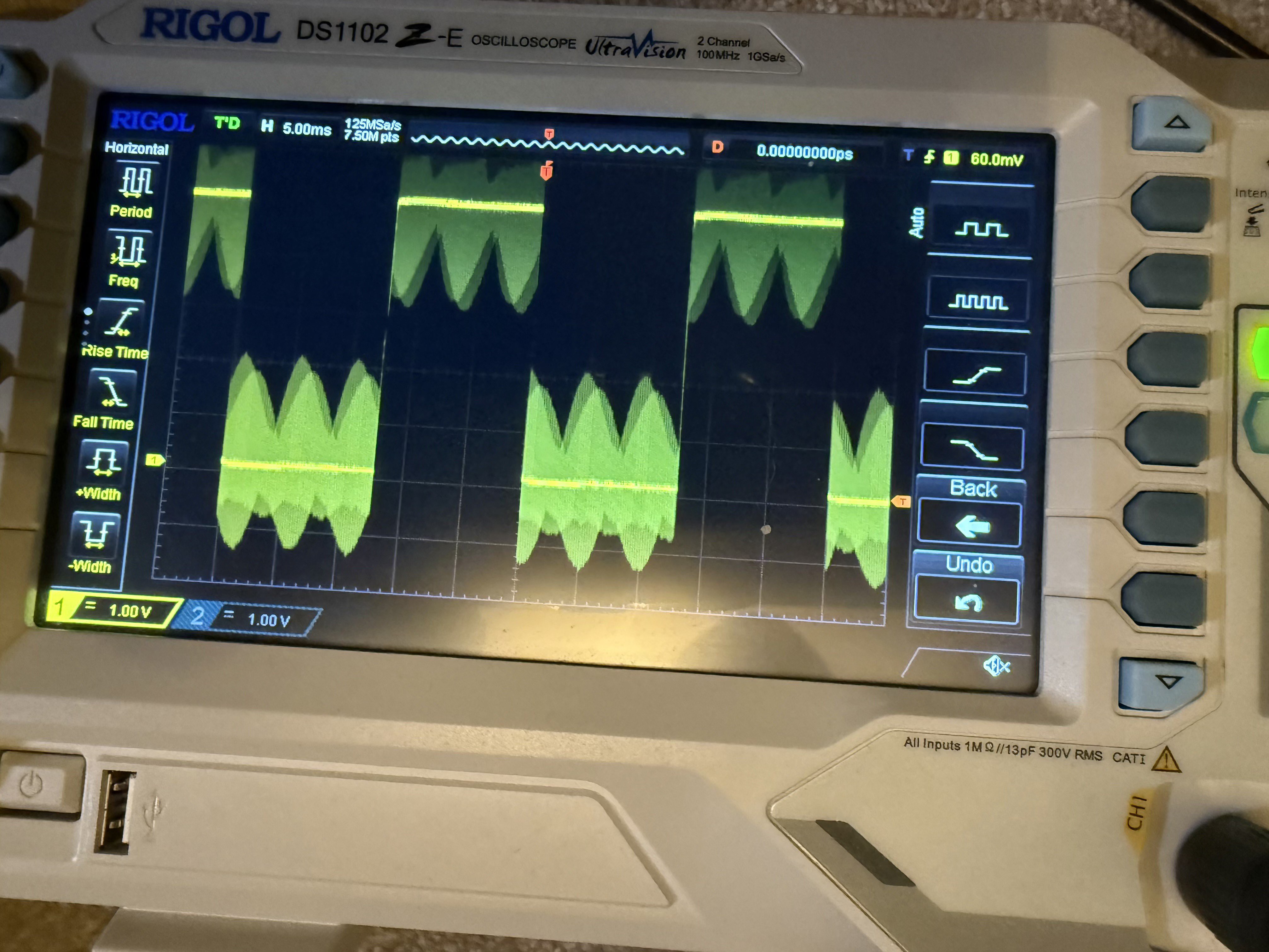
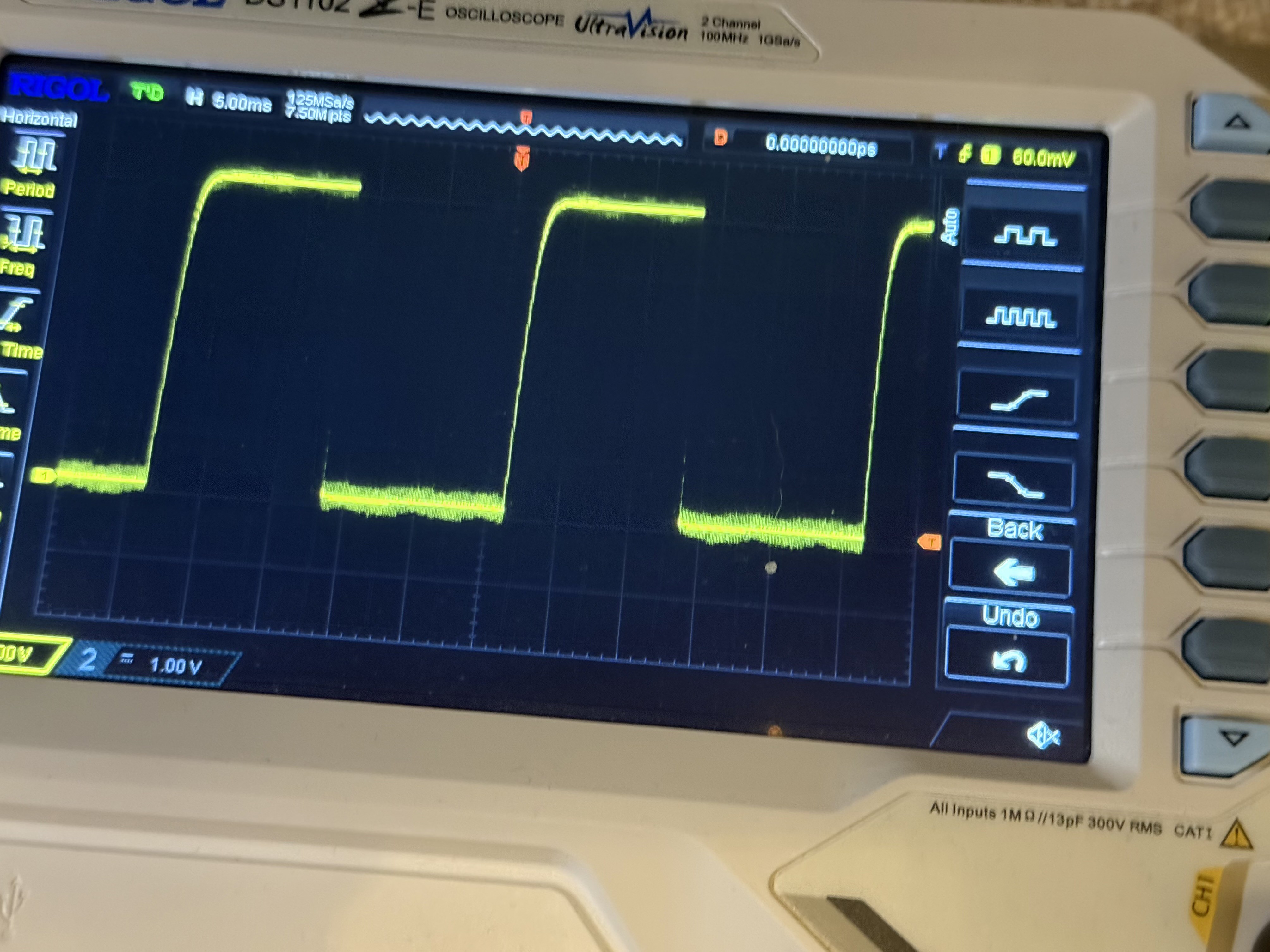
I initially didn’t add any to the PCB for the fans PWM line as there was no issue on my breadboard mockup. On the finished product, going over around 70% on the fan control suddenly introduced huge noise into the PWM square wave, and erratic fan speed readings with it. Bodging a 100nF cap across the pins fixed the noise at higher speeds right up, as well as the jittery fan! If you look really carefully (lol) at the scope photos you can spot the difference 😅

 WJCarpenter
 Androiders
 Arnov Sharma
 Mrinnovative