 Arnov Sharma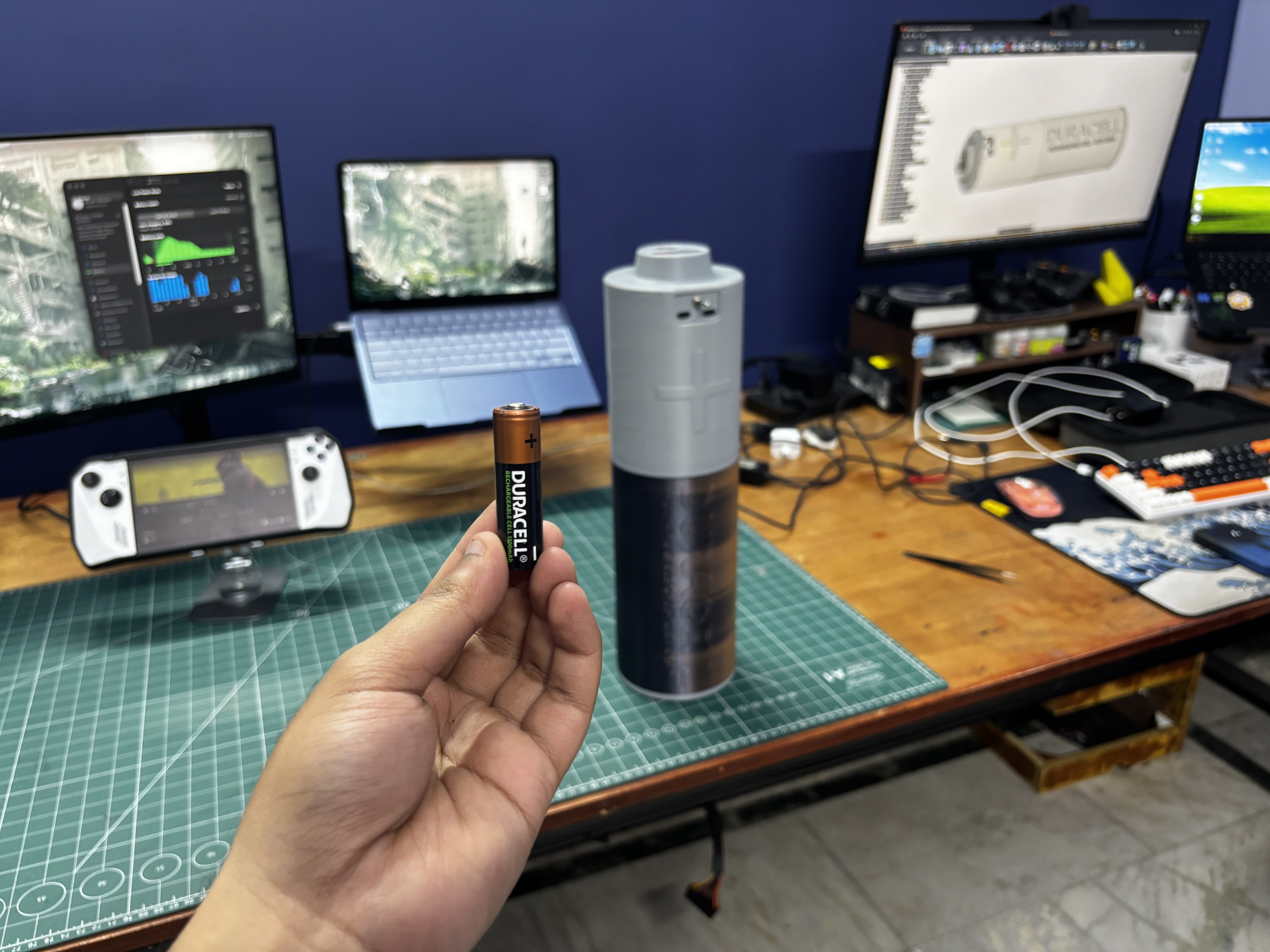
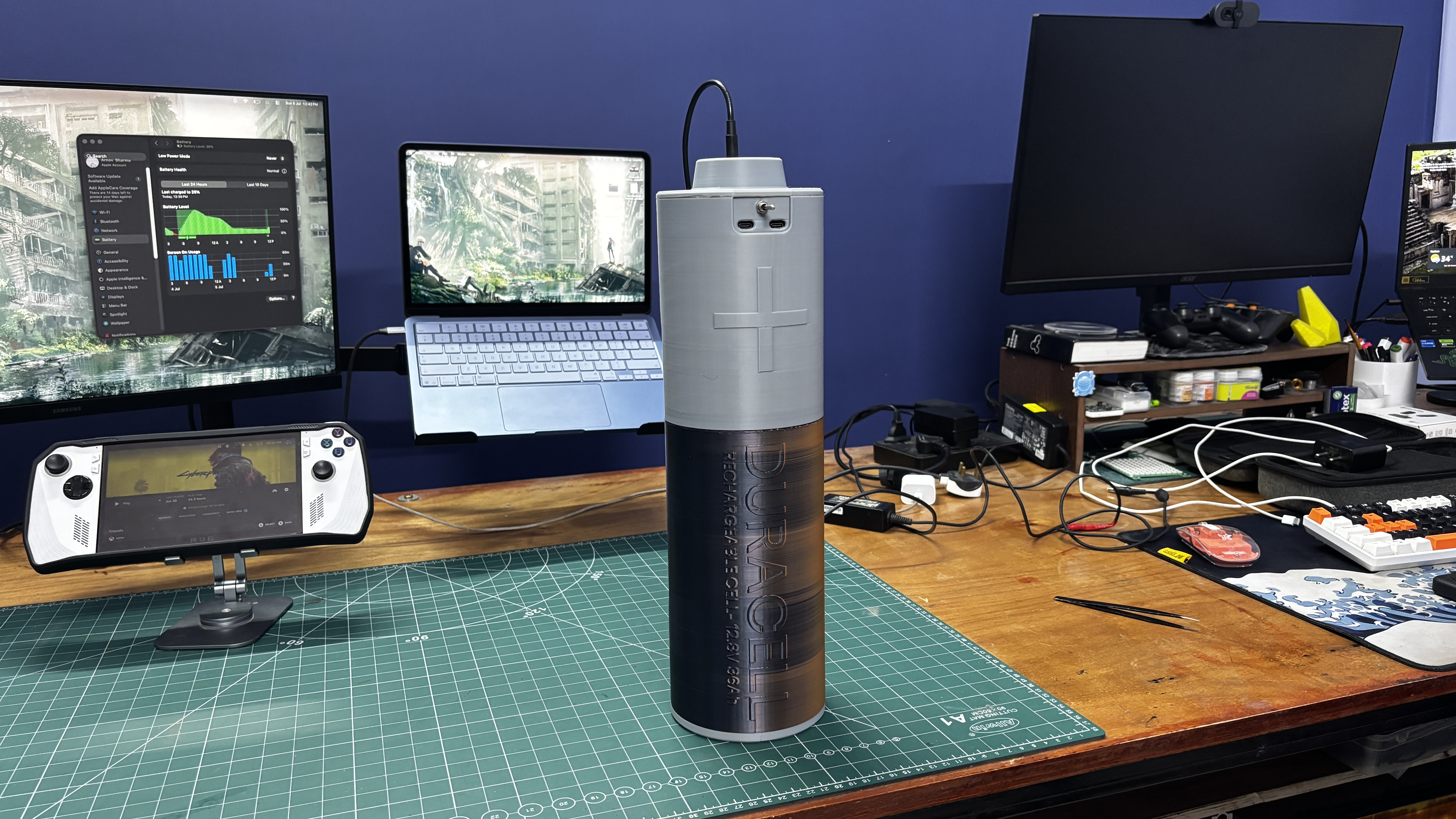
For the design of this project, I wanted to create something truly different from a regular battery pack enclosure. So, I modeled the entire battery pack to look like a ridiculously oversized Duracell AA battery.
Inside the enclosure is a custom-made battery pack built using LiFePO4 cells arranged in a 4S6P configuration. The completed battery pack has a nominal voltage of approximately 13.3V, a capacity of 36Ah, and stores roughly 470Wh of energy.
HARDWARE- LiFePO4 CELLS
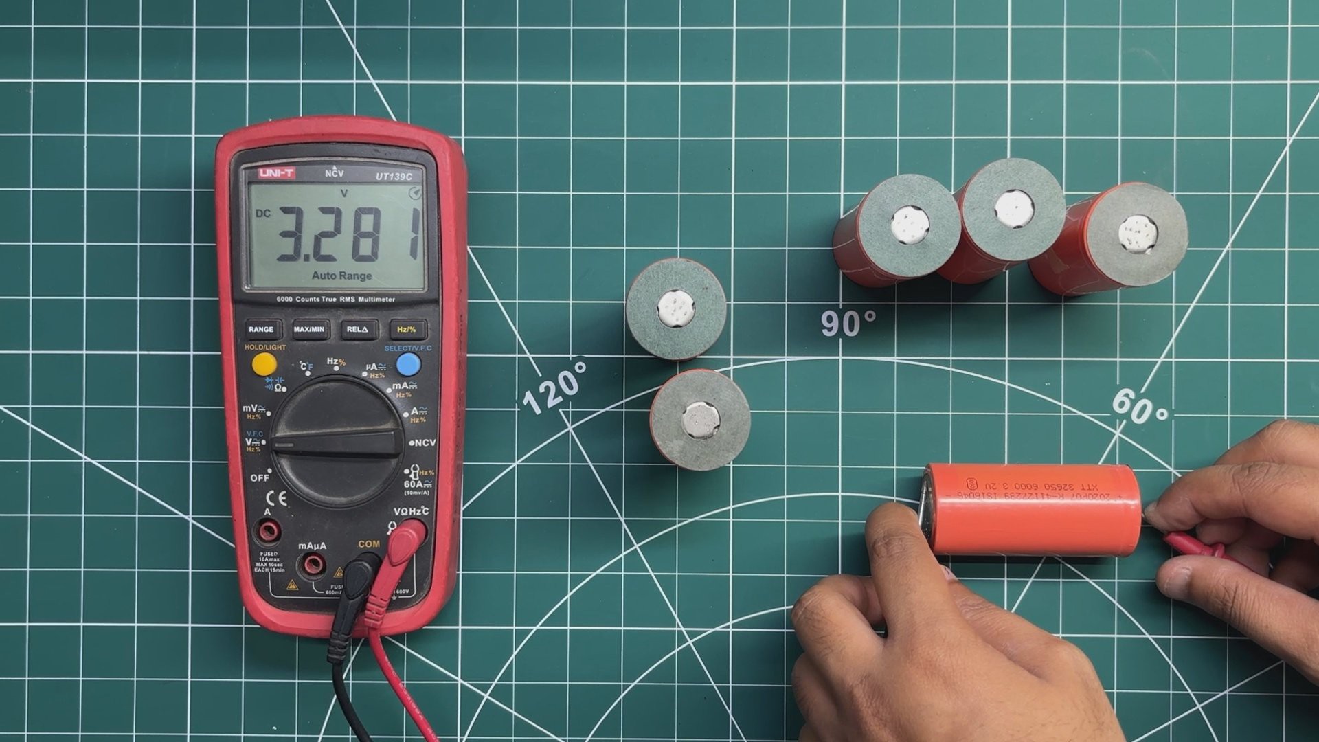
The main power source for this project is a set of LiFePO4 (Lithium Iron Phosphate) cells, each rated at 3.3V and 6000mAh. LiFePO4 cells are a great choice for this type of project because of their long cycle life, good thermal stability, and relatively safe chemistry compared to many other lithium battery types.
For this project, the idea is to build a 4S6P battery pack. This means six cells are first connected in parallel to increase the overall capacity, and four of these parallel groups are then connected in series to increase the pack voltage. In total, the battery pack uses 24 LiFePO4 cells.
Before assembling the battery pack, I checked the voltage of every individual cell using a multimeter and sorted them into groups with closely matched voltages. The cells used in this project were between approximately 3.270V and 3.280V.
Matching the cell voltages is especially important before connecting cells in parallel. When two cells with different voltages are directly connected in parallel, the higher-voltage cell will immediately start supplying current to the lower-voltage cell. Since lithium cells have very low internal resistance, even a relatively small voltage difference can potentially result in a high equalization current, causing excessive heat and creating a serious safety hazard.
Once cells are permanently connected in parallel, they behave electrically as a single, higher-capacity cell group because all the cells share the same voltage.
Series-connected groups work differently. In our 4S configuration, each parallel group can have a different voltage from the others because the BMS individually monitors the voltage of each series group through its balance connections. During charging, the BMS helps prevent individual series groups from exceeding their safe voltage limits and, if the BMS supports active or passive balancing, helps keep the series groups balanced.
However, the BMS cannot individually monitor or control each cell inside a parallel group. This is why checking and closely matching the voltage of all cells before connecting them in parallel is an important step in building the battery pack safely.
After checking all 24 cells and confirming that their voltages were within the required range, they were ready to be arranged inside the custom battery holders and connected to form the 4S6P battery pack.
HARDWARE- BMS
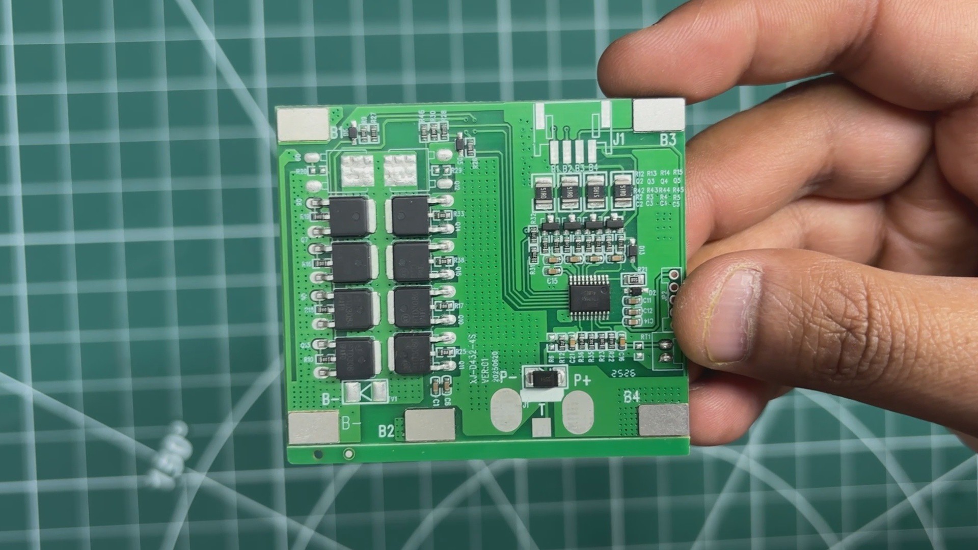
For managing and protecting the battery pack, I am using a 4S 20A BMS specifically designed for LiFePO4 cells. The BMS supports a 4S configuration with a nominal pack voltage of 12.8V and a continuous discharge current of up to 20A.
The main purpose of the BMS is to protect the LiFePO4 cells during charging and discharging. It provides essential safety features, including overcharge, over-discharge, overcurrent, and short-circuit protection.
The BMS continuously monitors the voltage of each series cell group and disconnects the battery pack if the voltage exceeds or drops below the safe operating limits.
With its 20A continuous discharge capability, this BMS is suitable for our 4S6P battery pack and allows us to safely charge the battery and power various devices connected to the output.
HARDWARE- PD MODULE
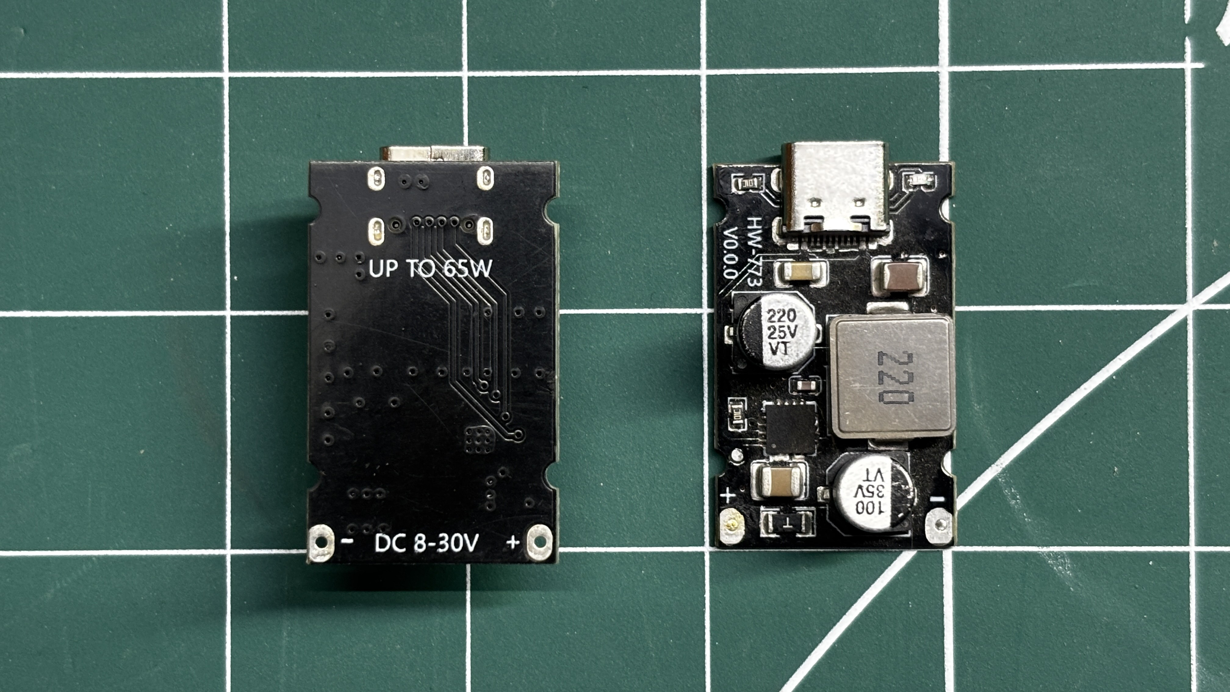
For the USB-C power output, I am using a 65W PD fast-charging module. This is a compact and highly efficient DC-DC step-down converter that supports multiple fast-charging protocols, including PD3.1 (PPS), QC3.0, Huawei SCP/FCP, and Samsung AFC.
The module accepts an input voltage of 8V to 30V and can provide up to 65W of output power through the USB-C port. It features intelligent PD negotiation, which automatically adjusts the output voltage between 3.3V and 21V according to the requirements of the connected device.
With a conversion efficiency of around 92–97%, the module produces minimal power loss and heat. It also includes built-in over-voltage, under-voltage, short-circuit, and over-temperature protection.
Its compact 32x20mm size makes it perfect for integrating into our giant battery pack and allows us to charge smartphones, tablets, handheld gaming consoles, and even PD-compatible laptops.
I found this really good guide on the internals of this PD Module, its schematic, and other working details.
https://www.beyondlogic.org/review-usb-pd-65w-fast-charging-module-xpm52c/
DESIGN
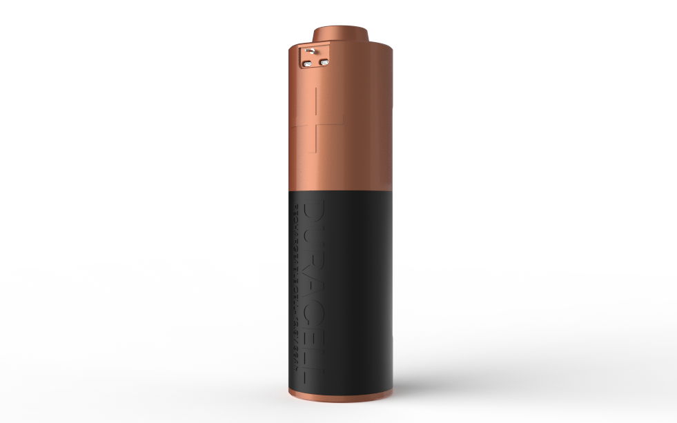
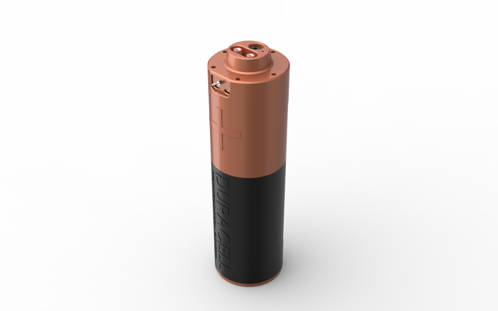
For the design of this project, my plan was to model the battery pack after a Duracell AA cell. However, instead of completely replicating the original design, I only used its basic cylindrical shape and appearance as inspiration. The rest of the parts were designed from scratch based on the specific requirements of the project.
I started by designing an internal battery holder that holds six cells in a parallel configuration. Four of these battery holders are then stacked together to form the complete cylindrical 4S6P battery pack assembly.
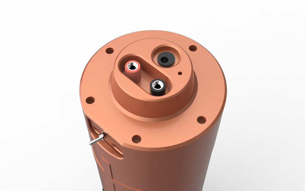
The Duracell-inspired outer enclosure is essentially a cover that fits around the cylindrical battery assembly. The top section was also designed to resemble the positive terminal of a regular AA cell. This section houses two banana plug connectors and a DC barrel jack for the main power connections.
On the front of the enclosure, I also added two USB Type-C openings for the dual 65W PD modules, allowing us to connect and charge USB-C PD-compatible devices directly from the battery pack.
The entire enclosure and internal assembly were designed from scratch using Fusion 360, with each part modeled around the dimensions and requirements of the battery cells, electronics, and output connectors.
CELL HOLDER
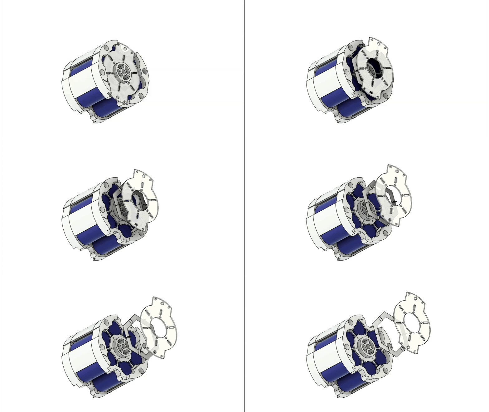
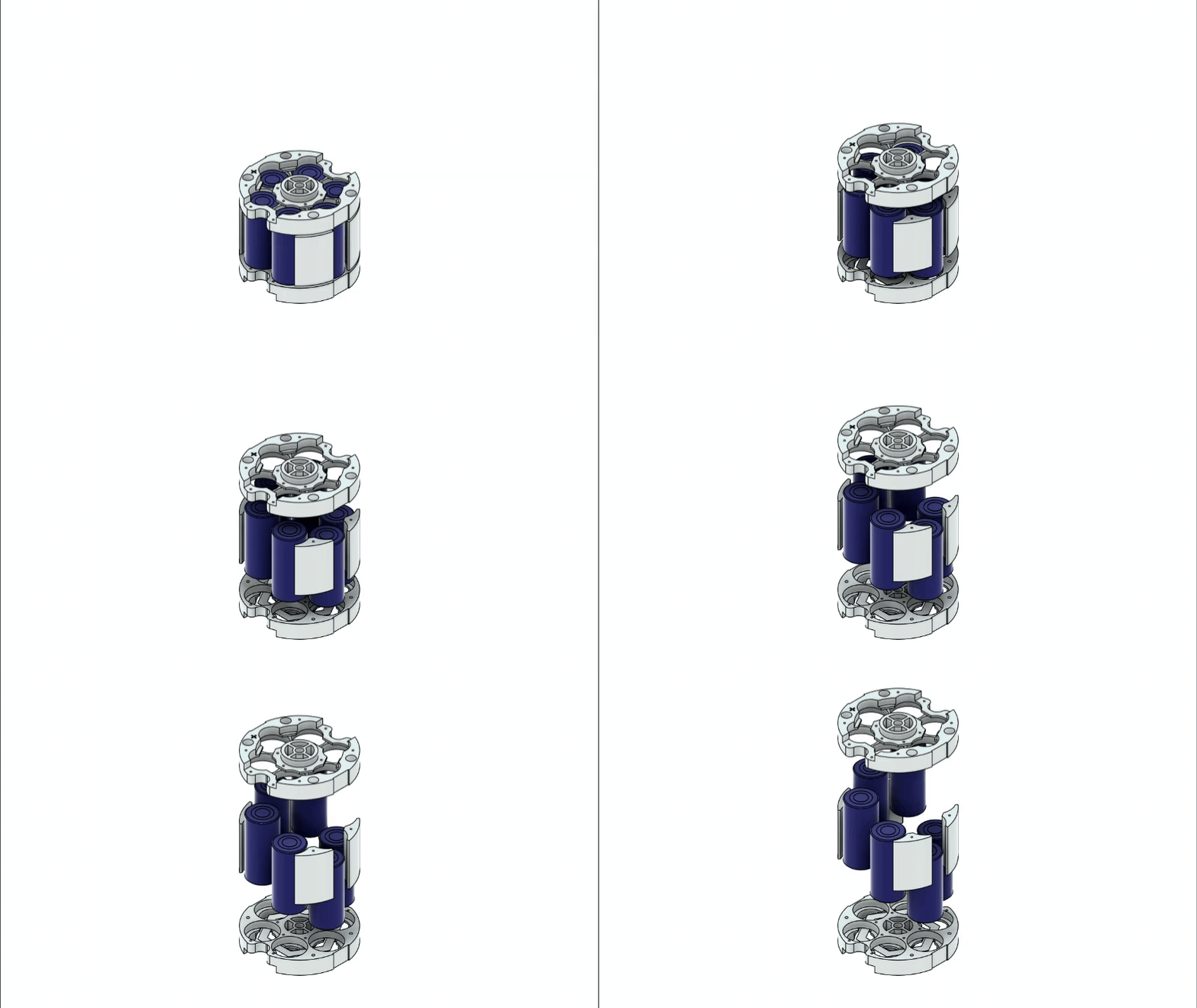
The core part of this project is the cell holder, which was designed to hold six LiFePO4 cells in a hexagonal arrangement.
The holder mainly consists of three parts: the top holder, the bottom holder, and four mid-support pieces. These mid-support pieces are placed between the top and bottom holders, and M2.5 screws are used to secure the top holder to the mid supports and the bottom holder to the mid supports. This assembly securely holds the LiFePO4 cells in place.
The top and bottom holders are open on one side, allowing access to the cell terminals. This exposed side is required so that nickel strips can be spot-welded to the cells, connecting all six cells in parallel. I also designed a custom hexagonal nickel strip, which I will make using standard nickel strips and a 3D-printed jig.
On both the top and bottom holders, I added a PCB that is soldered to the nickel strips. These PCBs are used to connect multiple cell holders together, allowing all four parallel groups to be connected in series.
CELL HOLDER GROUP
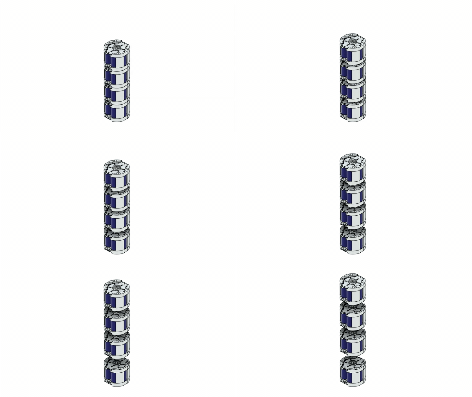
Once all four cell holders are assembled, they are stacked one above the other to form the complete battery pack. M4 nuts and bolts are then used to secure the assembly while simultaneously connecting the PCBs of adjacent cell holders. These PCB connections link the positive terminal of one cell holder to the negative terminal of the next, creating a 4-series (4S) battery pack.
The final result is a large cylindrical battery pack consisting of four cell holders connected in series. Each cell holder contains six LiFePO4 cells connected in parallel using the custom hexagonal nickel strips and connection PCBs, resulting in a complete 4S6P battery pack.
DURACELL SHELL & TOP PART
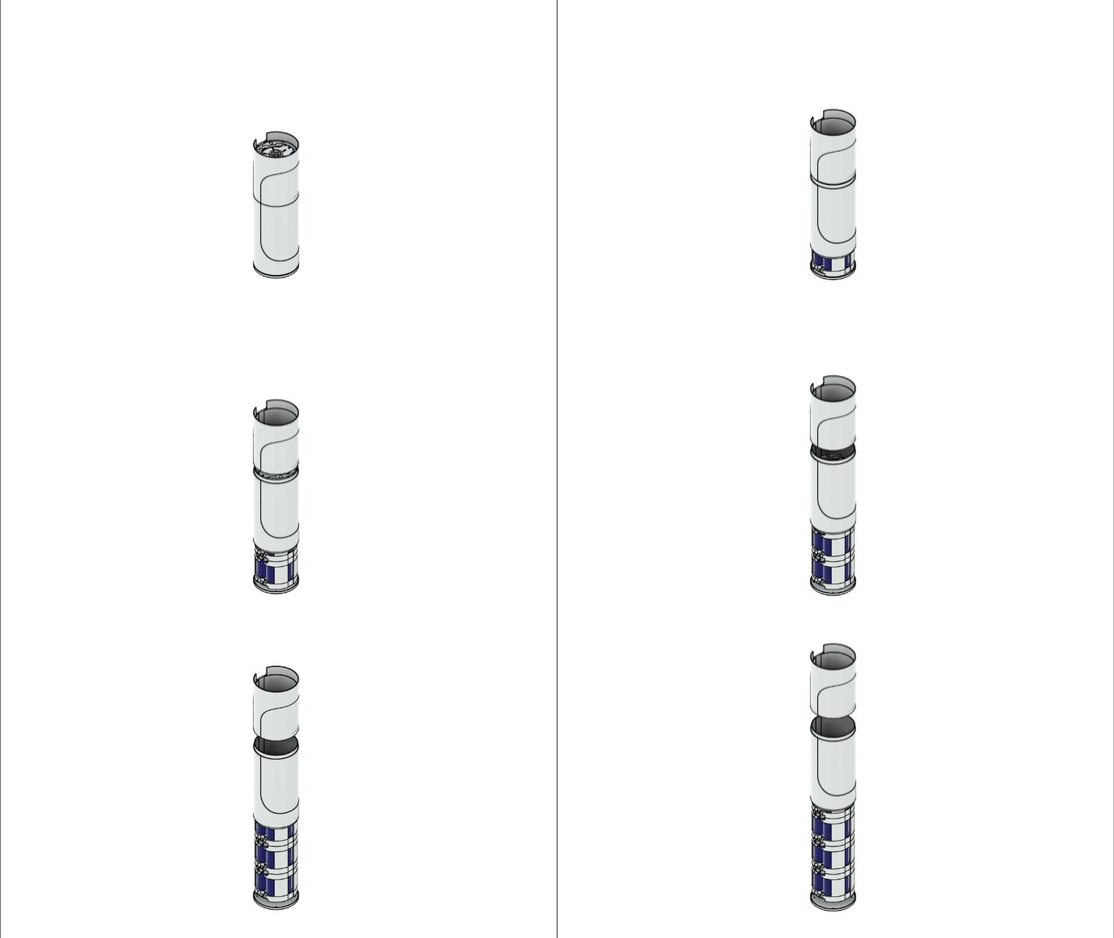
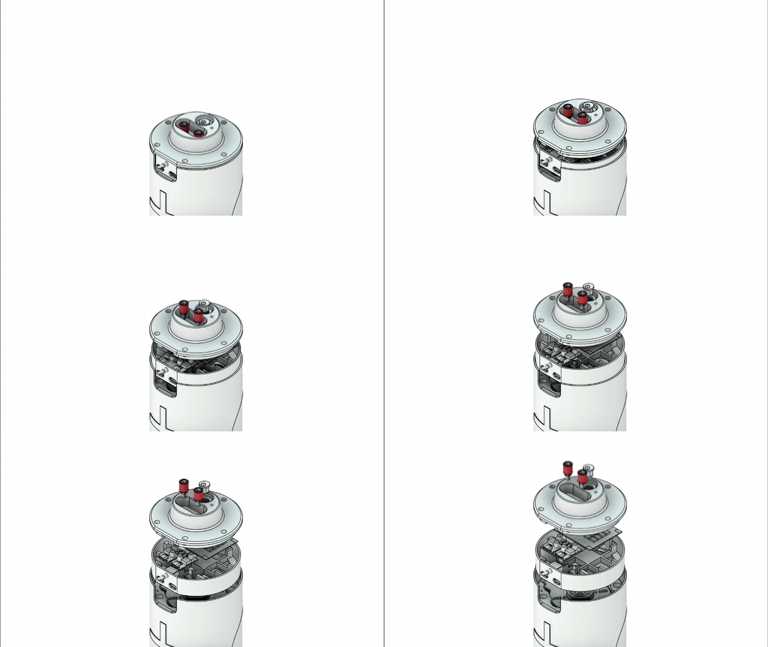
Next comes the outer shell, which mainly consists of three parts: the base, the Duracell shell, and the upper section.
Starting from the bottom, the base is attached to the battery pack assembly using four M2 screws, securing it to the bottom of the cell holder group. The Duracell shell then slides into position over the cylindrical battery pack and is held in place by the base. Finally, the upper section slides into place above the Duracell shell, completing the main body of the enclosure.
The top assembly is made up of two parts: an inner support and the top cover itself. The inner support is responsible for holding the 65W PD modules, the BMS, and most of the internal wiring, keeping all the electronics securely organized.
Also, we have added an opening for the Type C port in this inner support part and also a slide switch for turning the PD Module ON or OFF.
The top cover acts as the lid of the entire assembly and houses the main input and output connectors. For power output, I added two banana plug connectors, allowing the battery pack to power various external devices. A standard DC barrel jack is also included for charging the battery pack, along with an indicator LED that lights up whenever the charger is connected.
Besides housing the connectors, the top cover also locks the Duracell shell and the upper section in place. In combination with the base, it effectively sandwiches the entire enclosure together, keeping all the internal components securely assembled without any movement.
3D PRINTED PARTS
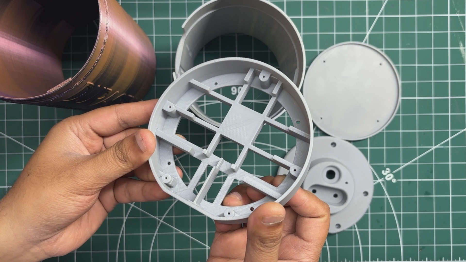
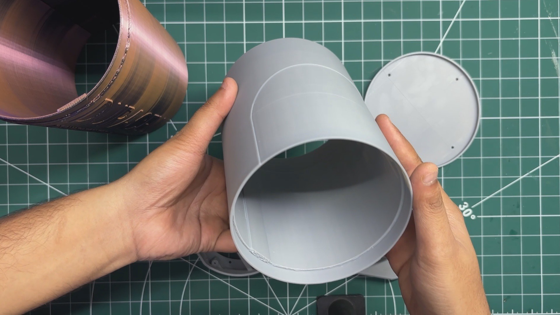
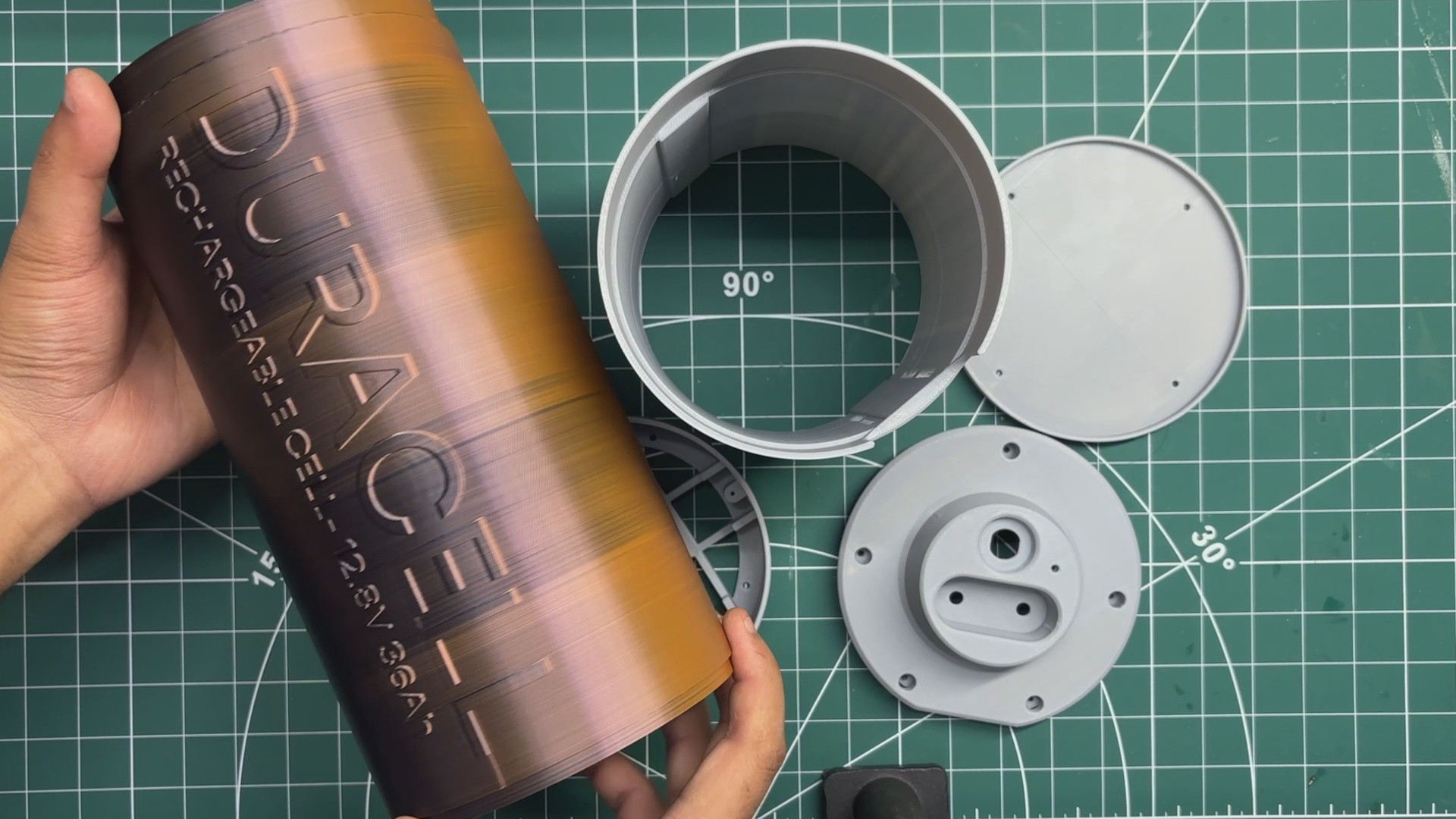
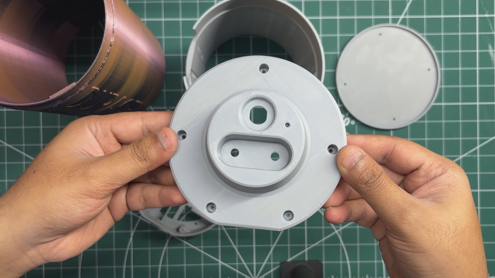
After finalizing the 3D model, all the parts were exported as mesh files and 3D-printed on our Anycubic Kobra S1 printer. I used white, grey, and dual-tone Hyper PLA filaments for the different parts of the enclosure.
All parts were printed using a 0.2mm layer height, a 0.4mm nozzle, and 25% infill.
For the parts that required support, I mostly used tree supports with a 0.3mm top Z distance. This provided enough clearance between the supports and the printed parts, making the supports relatively easy to remove after printing.
PCB DESIGN
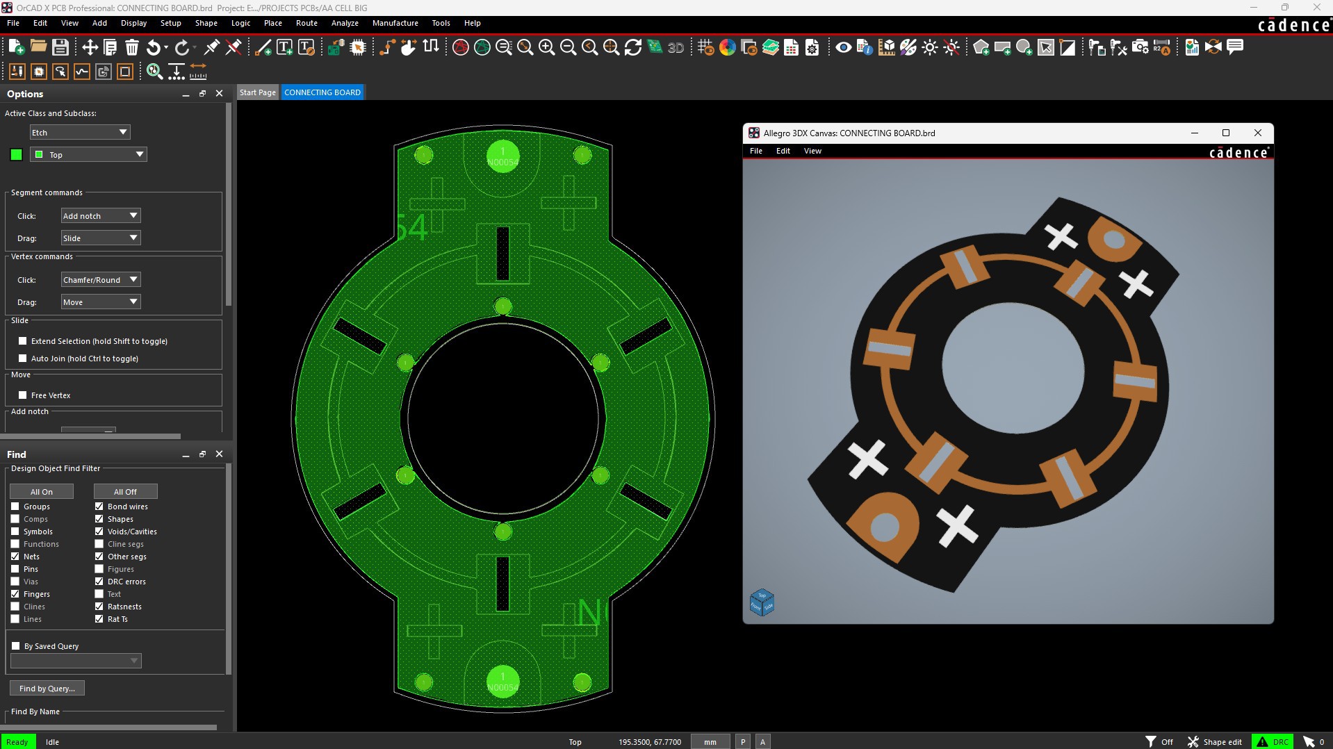
Following the board outline from my CAD model, I designed the connection PCB for this project. There is nothing particularly complex about this board—it is essentially a simple PCB with a large copper pour used to carry the battery current.
The PCB includes several slots where the custom nickel strips are inserted and soldered, along with mounting holes that allow it to be securely fixed to the cell holder.
Since the shape of the PCB is quite unconventional, I first exported the board outline as a DXF file from Fusion 360. I then imported this DXF into my PCB design software and used it as the board outline. This ensured that all the mounting holes and nickel strip slots were positioned exactly as designed in the CAD model, eliminating any alignment issues during assembly.
To simplify the assembly process, I added a + symbol on the top silkscreen layer and a − symbol on the bottom silkscreen layer. When mounting the PCB on the positive side of a cell holder, the side with the + marking faces upward. Likewise, when mounting it on the negative side, the PCB is flipped so that the − marking faces upward. This simple orientation system makes it much easier to identify the polarity of each cell holder and simplifies connecting all four holders together in series.
NextPCB PCB SERVICE
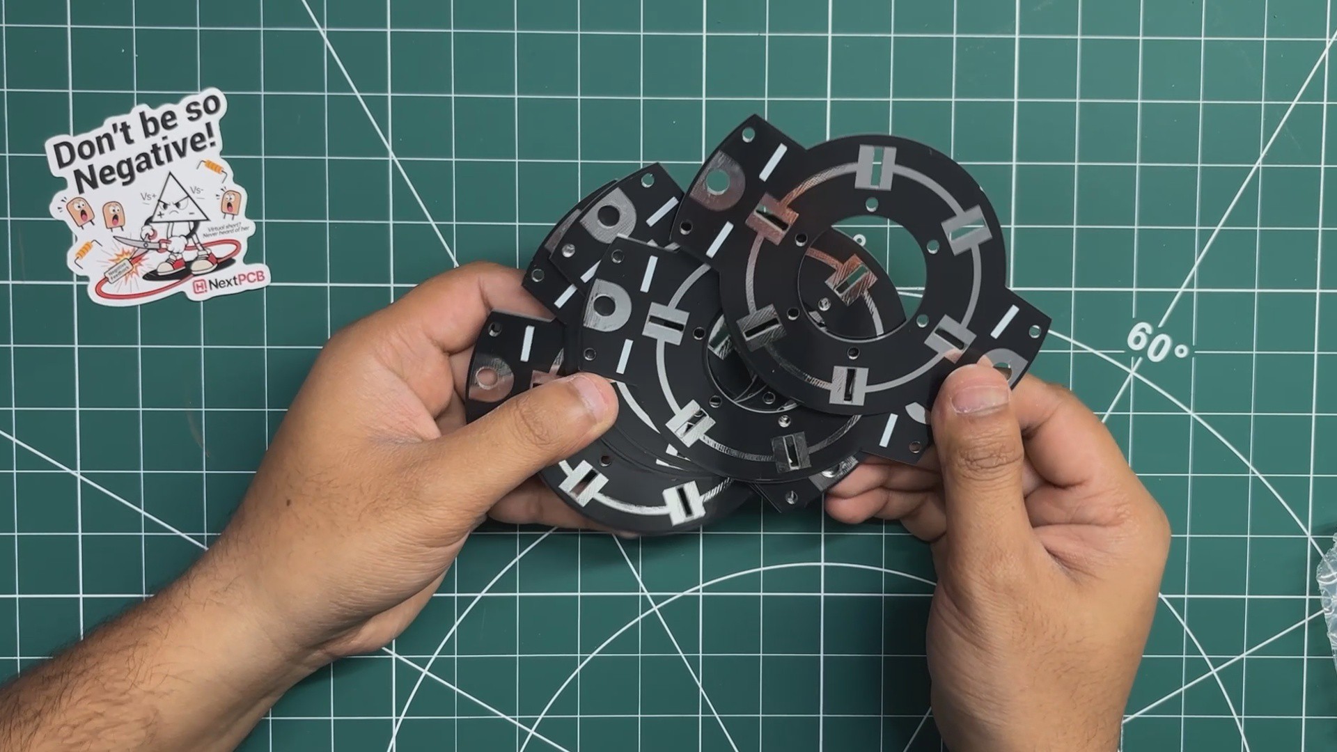
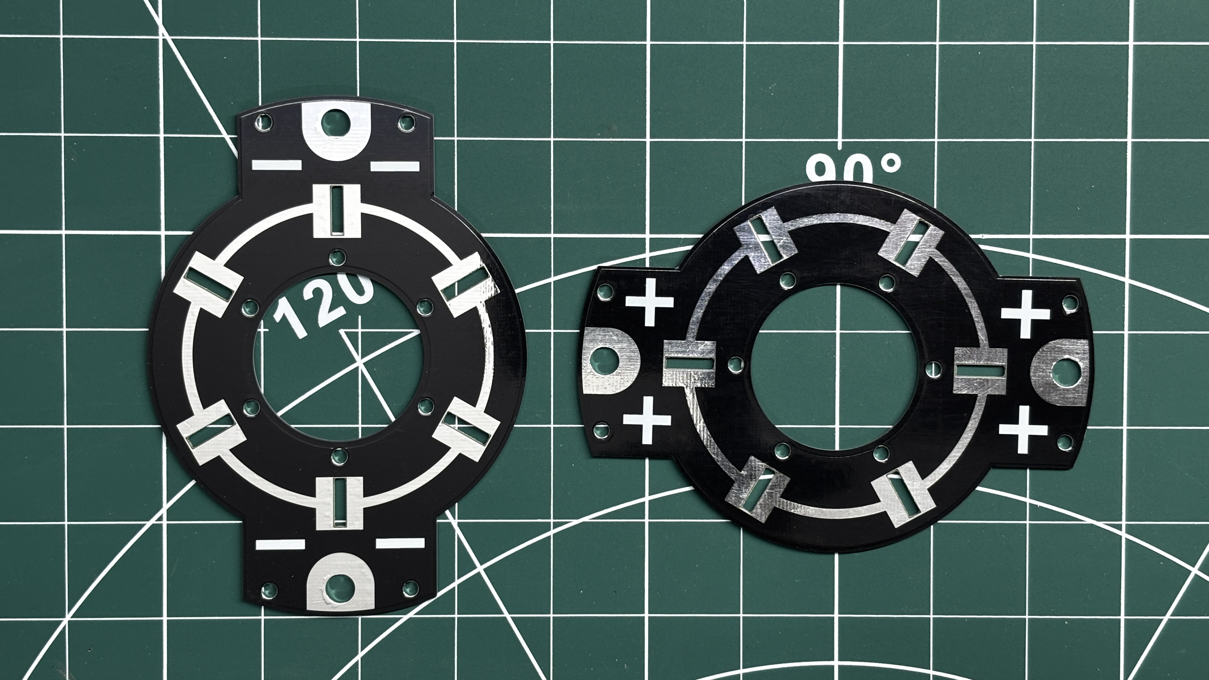
Gerber data for the PCB was sent to HQ NextPCB, and an order was placed for a Black solder mask and white silkscreen.
After placing the order, the PCBs were received within a week, and the PCB quality was pretty great.
In addition, I have to bring in HQDFM to you, which helped me a lot through many projects. Huaqiu’s in-house engineers developed the free Design for Manufacturing software, HQDFM, revolutionizing how PCB designers visualize and verify their designs.
Take advantage of NextPCB's Accelerator campaign and get 2 free assembled RP2040-based PCBs for your innovative projects.
https://www.nextpcb.com/blog/rp2040-free-pcba-prototypes-nextpcb-accelerator
This offer covers all costs, including logistics, making it easier and more affordable to bring your ideas to life. SMT services can be expensive, but NextPCB is here to help you overcome that hurdle. Simply share your relevant project, and they'll take care of the rest. Don't miss out on this amazing opportunity to advance your tech creations!
HQDFM: Free Online Gerber Viewer and DFM Analysis Tool
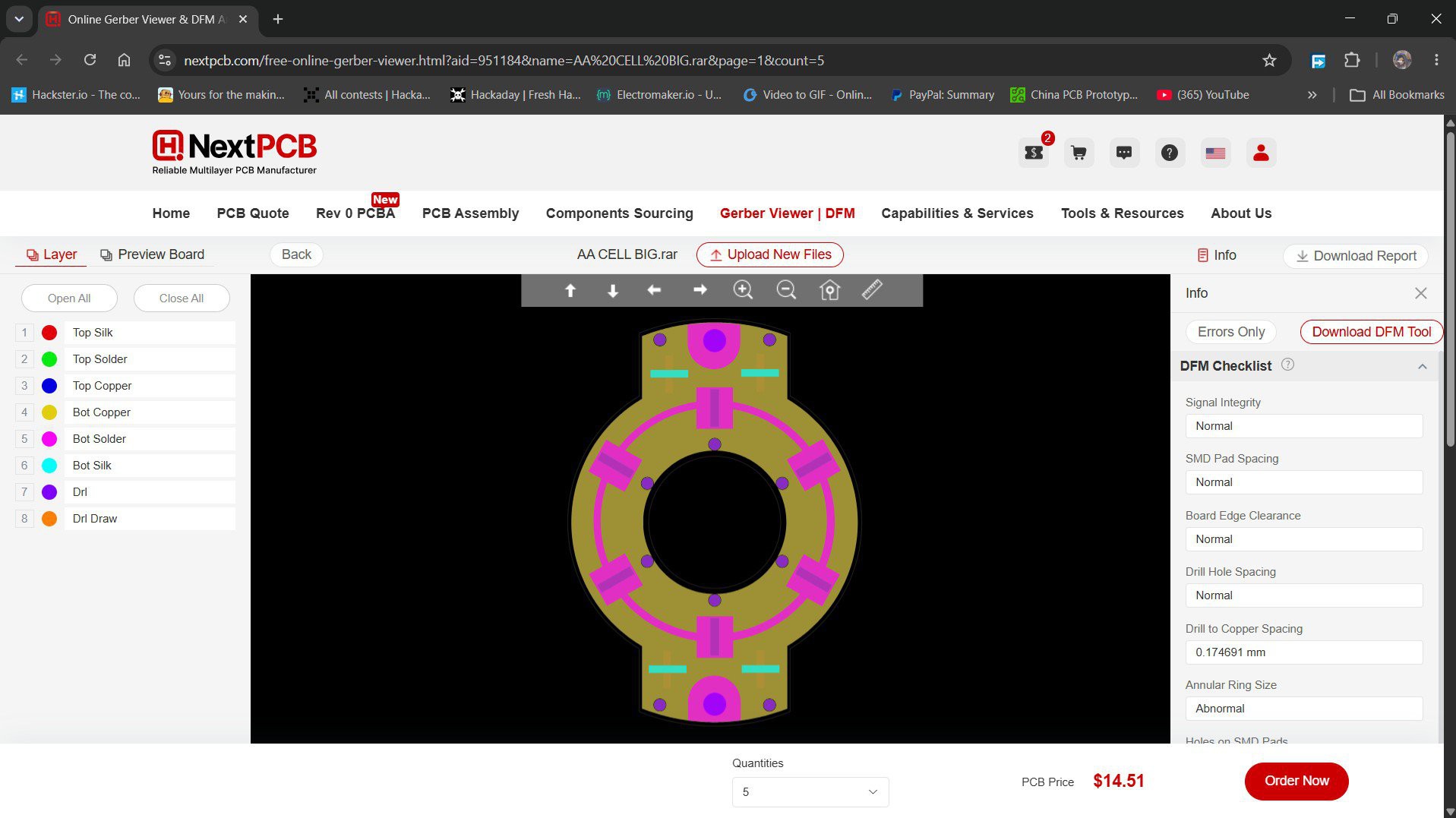
Also, NextPCB has its own Gerber Viewer and DFM analysis software.
Your designs are improved by their HQDFM software (DFM) services. Since I find it annoying to have to wait around for DFM reports from manufacturers, HQDFM is the most efficient method for performing a pre-event self-check.
This is what I see in the online Gerber Viewer. It's decent for a quick look, but not entirely clear. For full functionality—like detailed DFM analysis for PCBA—you’ll need to download the desktop software. The web version only offers a basic DFM report.
With comprehensive Design for Manufacture (DFM) analysis features, HQDFM is a free, sophisticated online PCB Gerber file viewer.
With over 15 years of industry experience, it offers valuable insights into advanced manufacturing processes. If you’re looking for reliable PCB services at a budget-friendly price, HQ NextPCB is definitely worth checking out.