Close
0%
0%

Unbeatable purely mechanical Tic Tac Toe Machine

A 3D printed machine which never looses a game of Tic Tac Toe

Similar projects worth following
This project is about a 3D printable machine which can play a perfect game of Tic Tac Toe as the second player. Purely mechanical, no microcontrollers, no electronics, no batteries.

It is based on a modified vintage edge-notched card system to implement a physical database which acts as a lookup table for any reachable board state and returns the best move for that.

To input a move, the human turns one of 9 knobs on the front panel and pulls a release handle. Inside the machine, a grid of rods aligns with cutouts on the stacked cards. When the current board state perfectly matches the physical slots on a specific card, gravity drops that card down. Pushing the handle back in shifts the dropped card sideways, which actuates an indicator plate to reveal the machine's reply move (an 'O') through the front window.

The main challenge was to calculate the slots of the cards and to reduce them from originally 301 to only 65 cards.

History

Built in 1978 by MIT students Danny Hillis and Brian Silverman, the Tinkertoy Computer is a legendary mechanical marvel that plays a perfect, unbeatable game of Tic-Tac-Toe without a single microprocessor.

Rather than calculating moves on the fly, the machine functions as a massive, physical lookup table. The creators compressed every possible game state down to 48 unique configurations, which were hardcoded into the framework as "memory spindles."

To play, a human inputs the current board state into a mechanical "read head" and turns a hand crank to power the machine. As the head descends, it physically scans the spindles. When its fingers find the exact structural match for the board state, the mechanism drops into place, triggering a linkage that points to the computer's winning counter-move. It is a brilliant piece of engineering, but it is also massive.
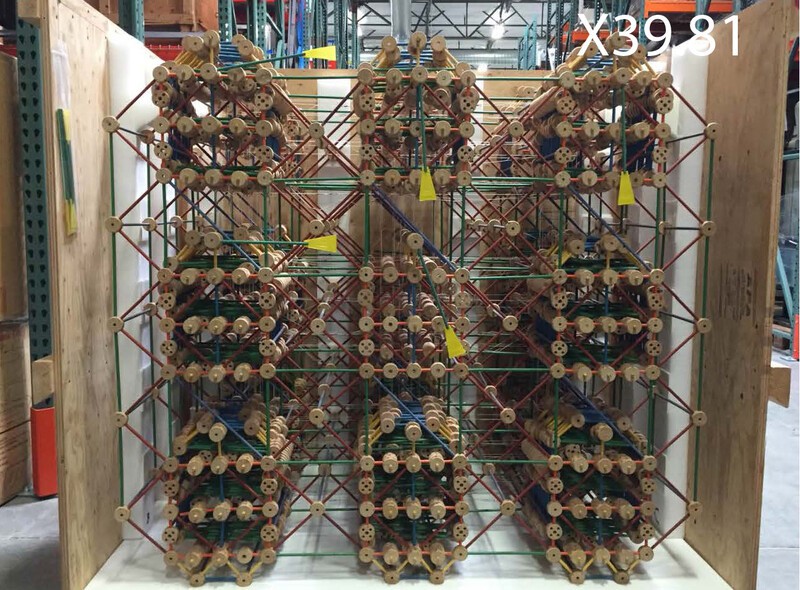
Source: Original Tinkertoy Computer / computerhistory.org

Introduction

My machine, which I call the "XXO Master," solves the exact same problem but at a fraction of the size. While the Tinkertoy computer is a massive 130×122×89 cm, the XXO Master fits on a desk at just 20×12×12 cm—and uses a different mechanical architecture to look up the best move.

The rules of the machine are simple: The human ('X') always goes first, and the machine ('O') will always reply. The machine never makes mistakes—it will never lose, and it will always seize an opportunity to win.

The Machine Design
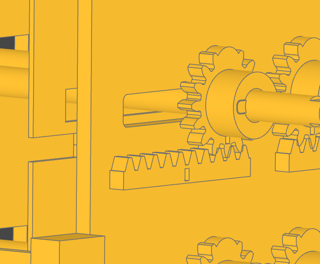
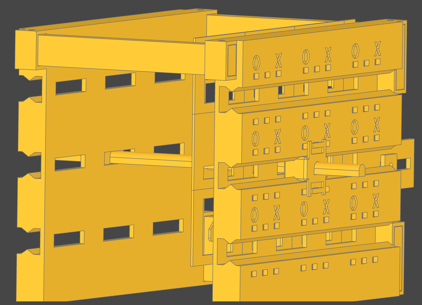
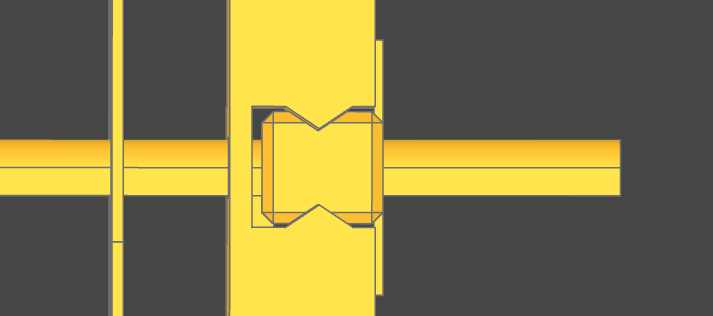
The core of the machine consists of 9 horizontal rods, each equipped with a gear at the front and back. These gears ride on a rack (a rack-and-pinion system), ensuring that when the user shifts a rod to the left or right, it translates perfectly parallel to its original position without binding (see my Project Log, where I describe why a simple linear rail didn't work out)
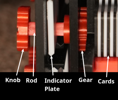
These 9 rods serve two simultaneous functions: Display and Logic.

1. The Display (Indicator Plates)
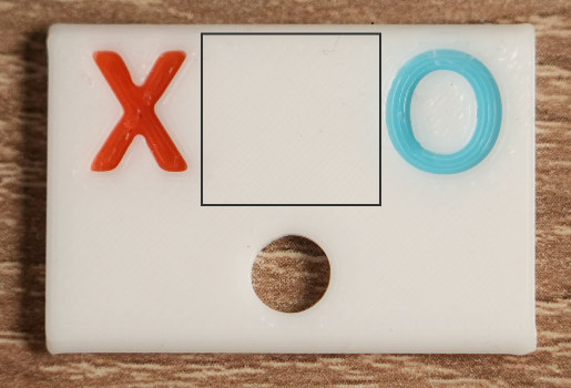
At the front of the machine, the rods thread through small indicator plates printed with an 'X' on the left side, an 'O' on the right side, and a blank space in the center. These plates ride on small upper and lower rails. The front frame of the machine acts as a mask, featuring small square windows so you can only see one section of the plate at a time. When you shift a rod to the left or right, it physically moves the plate, revealing the 'X' or 'O' piece you just played on that specific field.
2. The Logic (Mechanical Punch Cards)
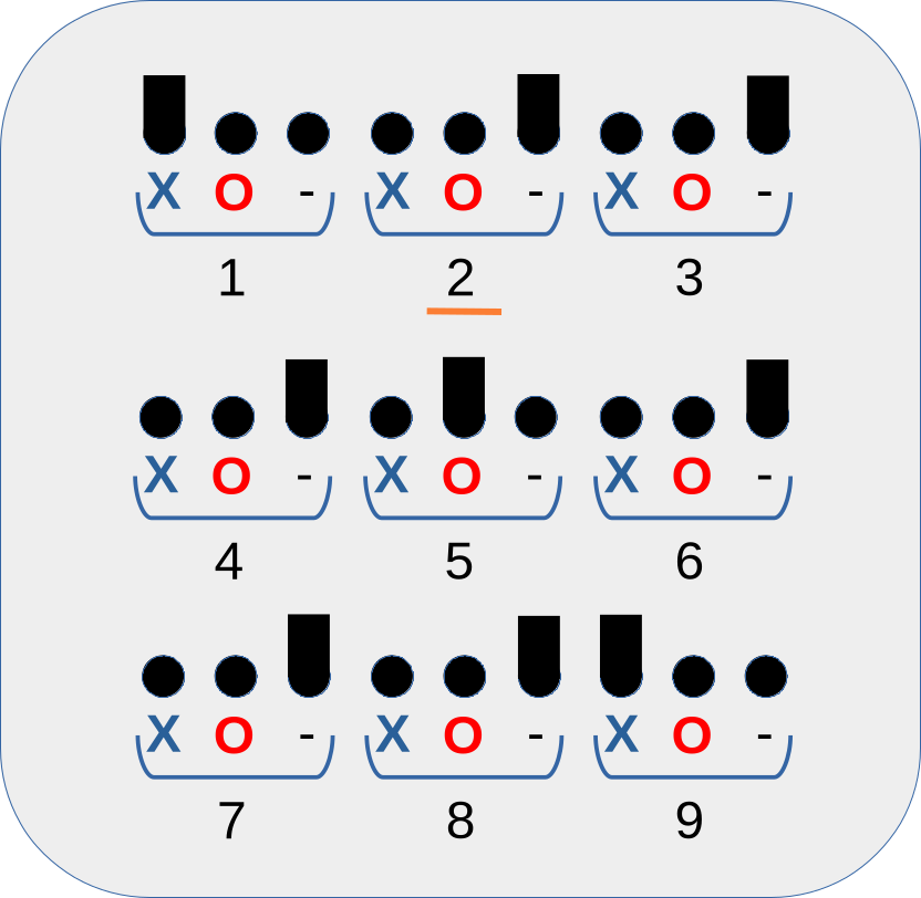
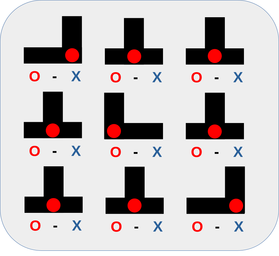
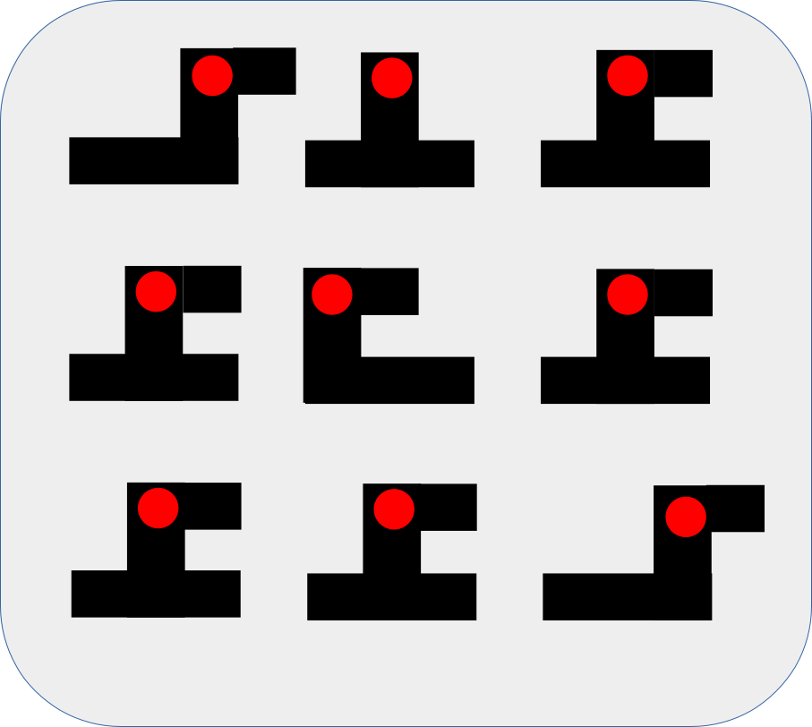
Internally, the rods pass through a stack of logic cards. Each card is divided into 9 fields corresponding to the board, and each field features a specific pattern of slots. At the start of a game, all rods rest in a horizontal baseline slot. Extending straight up from this baseline is a vertical slot, positioned either on the left, right, or in the center.

When the human makes a move, the rod positions shift. When the current board state (represented by the physical alignment of all 9 rods) perfectly matches the slot pattern on a specific logic card, gravity drops that specific card down. Finally, the dropped card is pushed to the left by the user via a "release handle." This horizontal motion forces one specific rod to slide to the left alongside it, shifting its front indicator plate to display an 'O'. The machine has just physically calculated and executed its reply move.

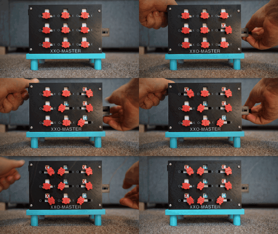
The following animation illustrates how a user enters their first move in the top right corner, how the logic card drops once aligned, and how the reply move is executed:
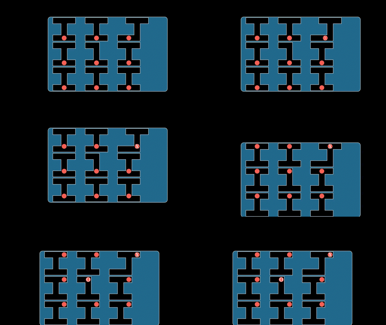
Note: The animation shows only the core concept but does not show the final design of the cards!

The Card Design

First, I wrote a Python script to generate the entire Tic-Tac-Toe game tree using a simple Minimax algorithm. This yielded 447 unique board states that require a reply from 'O' (excluding final states, win states, etc.). I optimized the script further: when there are multiple...

Read more »
minimized_rules.json

The lookup table by using wildcards

JavaScript Object Notation (JSON) - 1.27 kB - 07/21/2026 at 10:53

Download

raw_moves.json

The lookup table for the minimized game tree

JavaScript Object Notation (JSON) - 5.88 kB - 07/21/2026 at 10:53

Download

PhotoTopSide.jpg

JPEG Image - 2.71 MB - 07/17/2026 at 17:21

Preview

  • From Rods moving on Linear Rails to a Rack and Pinion design

    Alex Krasno07/17/2026 at 17:06 0 comments

    In my first design I used linear rails at the front and back frame with the idea that the user can move the rods to the left or right:

    However, after printing this design I quickly found out that even with the best designed rails, there was no way to keep the rods in sync with the front and back. If I tried to move the rods at the front they didn't move at the back (or moved only slightly). The lever was just too long applying an off-center twisting torque. Of course, pushing the rods from the center wasn't an option because this is where the cards will be.

    So, finally I ended up and replaced the linear rails with a "Rack and Pinion" design i.e. I attached a gear at the front and back of the rod and added a rack to the front and back frame. Now, when the user moves them to the left or right, they would turn in one or the other direction and the gears would keep the position of the rod in sync.

  • The breakthrough - An old database system before computers were invented

    Alex Krasno07/17/2026 at 15:51 0 comments

    Since my last two ideas tried to reflect the game tree, I needed something that reacts on a given board state. I stumbled across a vintage system called Edge-notched cards.

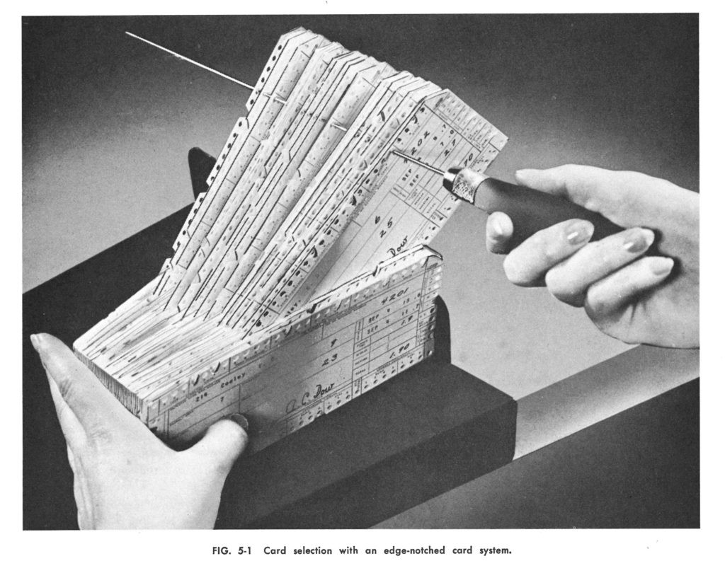
    This system was used to sort a large number of cards by specific properties encoded via the presence or absence of notches:

    And then you could use it as a paper database by passing needles through the selected holes:

    Source: "The Bourne Collection" / computerhistory.org

    Finally, you got all cards that matched a certain property.

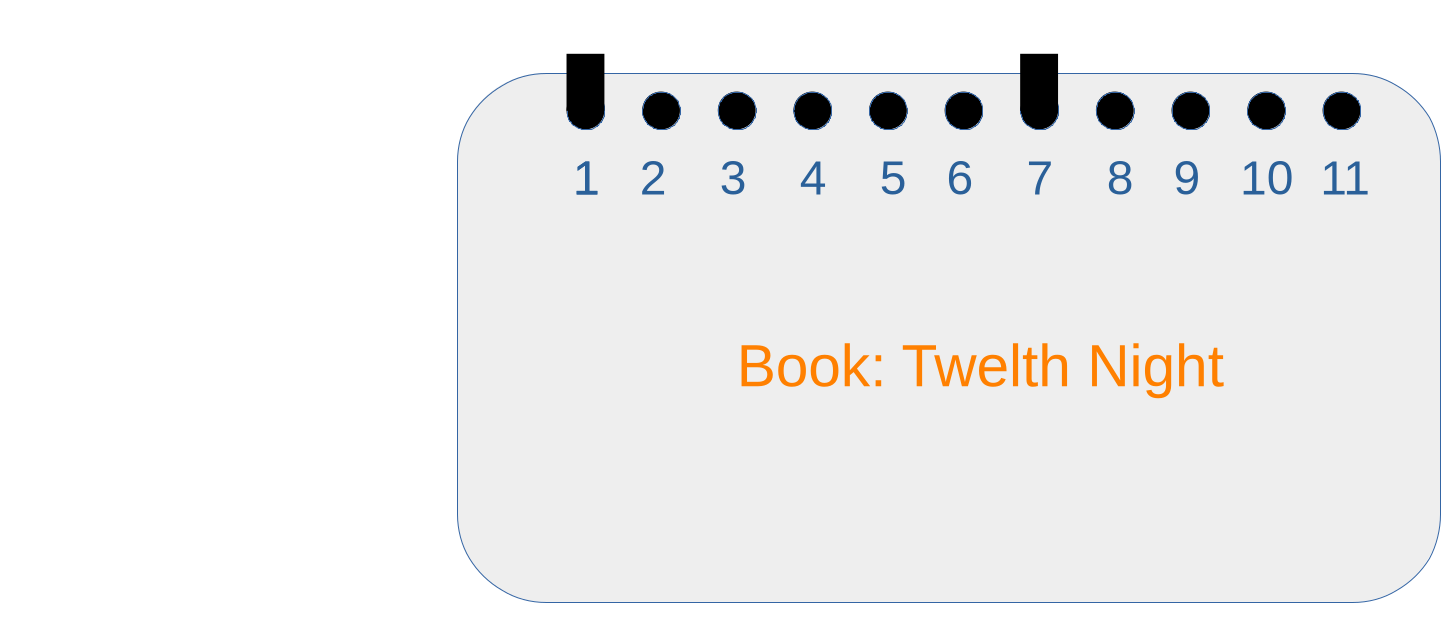
    I tried to apply this concept to our Tic Tac Toe game. Each field could be represented by one hole:

    However as you can see lining them up in one row takes quite a lot of space whereas the rest of the card stays quite empty. So I re-arranged them in a grid:

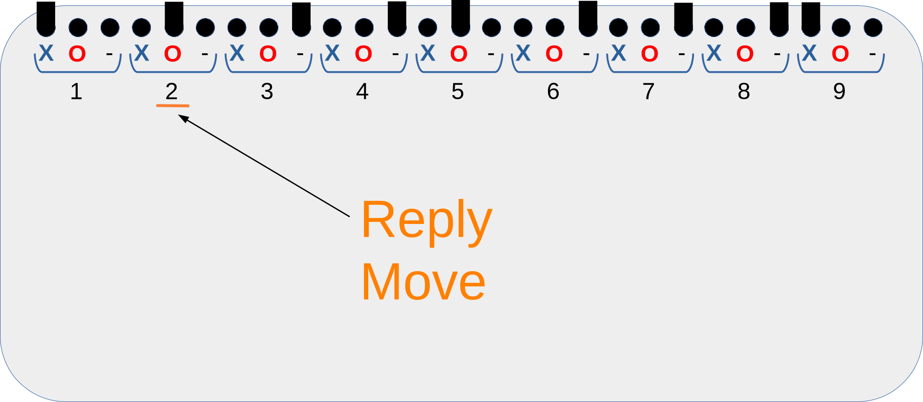
    Every field can only have one of the states empty, X or O. So I connected the holes to slots and used rods as needles:

    With this, we are now able to encode a board states i. e. if the board state matches our slot pattern the card will drop one level down. But how do we encode the reply for each state? It would be great if for the reply we are able to move the corresponding rod to the right position.

    This is how a dropped card would look like. All rods are now at the top of the slot. The idea is now to move the card to one direction (left) so that it shifts the rod for the reply too while keeping the other rods in place.

    Voila, we found the main principle to enter a move (by moving the rod to the right for 'X') and to show the reply move 'O' by lettings the card move it to the left. 

    If the rods are now combined with an indicator plate showing X, O or empty through a little window then we have both, the input and the output at the same place.

  • My second idea - A nested drawer system

    Alex Krasno07/13/2026 at 09:08 0 comments

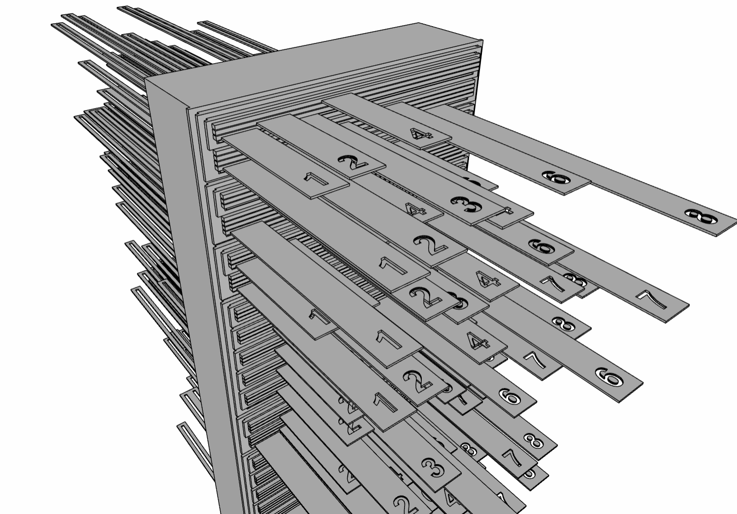
    The second idea used a nested drawer system (instead of nested wheels). There are 9 big drawers for the first move where each of them contains a stack of smaller drawers for the second move and those contain smaller drawers for the third move and so on until the drawer becomes only a single card (for the leaf states). Each drawer and each card has a latch at the front with the field (1-9) you want to play and a hook at the back.
    The idea is:
    The front latches for the bigger drawers are very long so that if you would create a big wall with slots you would only see 9 latches from 1-9. Then you pull this latch and the drawer moves to the front. While doing so there are two things happening:
    1. The hook at the back would pull a wire which is connected to the Tic Tac Toe board to show the move you made and the reply move. Let's say one straigt wire from top till bottom for each field.
    2. The latches of the second drawer would become visible through the wall (because you are pulling the drawer and all of its sub-drawer towards you). Those new latches show the fields which are available to play the next move.

    I also had to discard this idea, because the machine was just too huge. Stacking all drawers on top of each other (the picture shows only a drawer for the first move) is not practical. You would need to put the drawers for the first 9 moves next to each other which makes it then even more difficult to connect the wires to a single board.
    Another disadvantage is that this represents only a position in the game tree but not really the game state. This means that even if you reach the same position by different moves, they cannot be combined and instead have their own representation by a drawer or card - quite a waste of space and material.

  • The very first idea

    Alex Krasno07/12/2026 at 21:31 0 comments

    I thought about how I can map the logical game tree to a physical representation. I ended up with a big wheel containing all 9 moves that the human can do in the first step with a little box indicating what the reply move would be. From this position of the wheel you have a smaller wheel where you can make the next move and so on. Basically a recursive/nested selection wheel. This was the final result, but I quickly found out that it was not really printable, because the last wheels were too tiny.

View all 4 project logs

Enjoy this project?

Share

Discussions

Christian Walther wrote 07/29/2026 at 18:36 point

I haven’t fully thought this through, but it seems to me like the hole in the cards for wildcard “*”, shaped like

XXXX

XX

XXX

could actually be shaped like

XXX

XX

XXX

(the slot at the top doesn’t need to extend all the way to the right, there can’t be a rod there that mustn’t be moved, otherwise the card would not have dropped)

and that would help with the resetting, because the higher slope on the slanted edge would help push misaligned rods into place.

I found it interesting that the cards appear to drop in a nice parallel movement – I would have expected that if a card is only supported by say the top left rod (matches all the other 8), then it would sag a bit at the right edge, tilt, and wedge itself.

  Are you sure? yes | no

Christian Walther wrote 07/29/2026 at 20:36 point

Scratch that, I’m wrong. The extended slot is needed so the player can move a rod there *after* the card has dropped, because dropped cards stay in their shifted-to-the-left position. (What if that wasn’t the case, but the path of a dropped card was not down-left but down-left-down-right?)

  Are you sure? yes | no

Similar Projects

Does this project spark your interest?

Become a member to follow this project and never miss any updates