Arnov Sharma

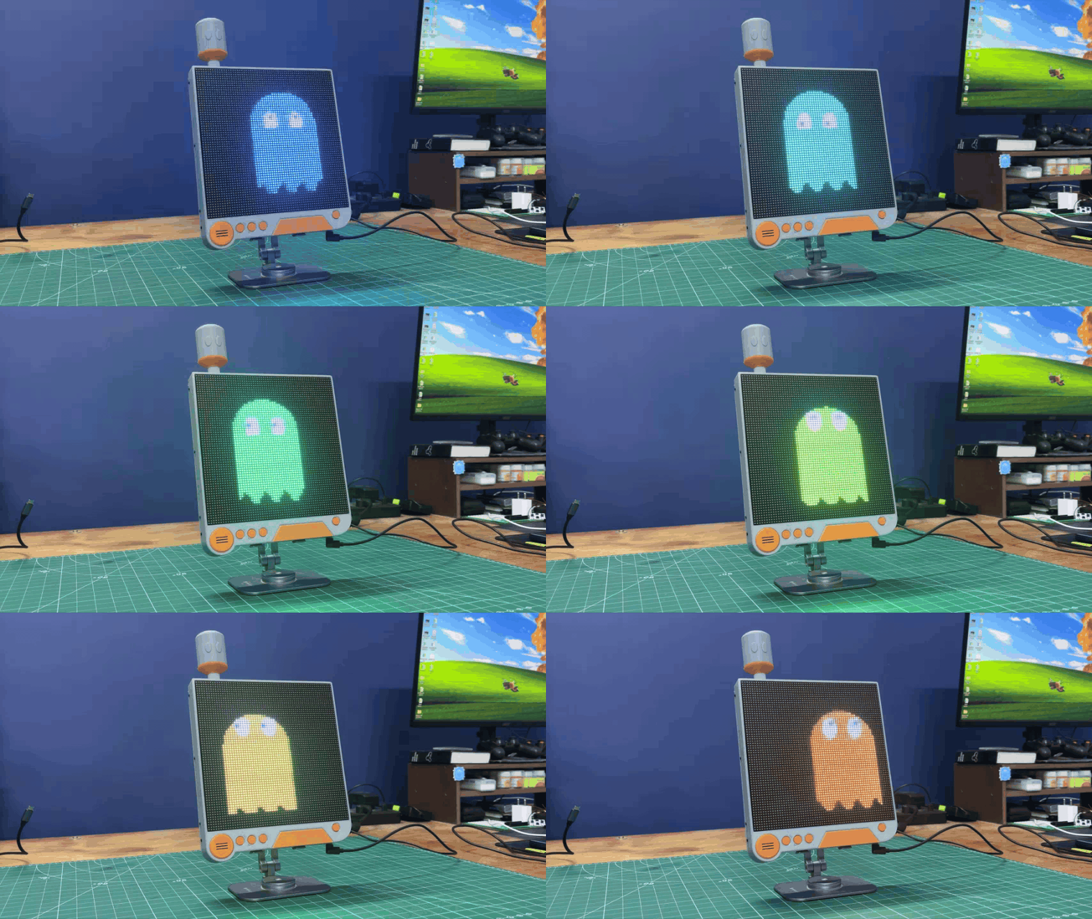
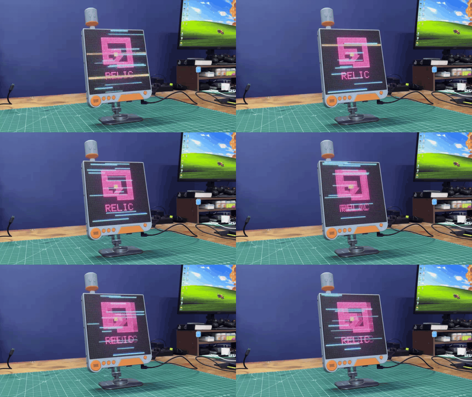
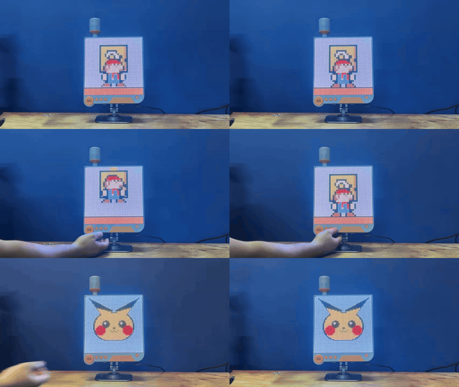
Project Gestalt is powered by a 3.7V, 2600mAh lithium-ion cell, providing approximately four hours of battery backup, which is pretty decent for a device running a total of 4, 096 RGB LEDs.
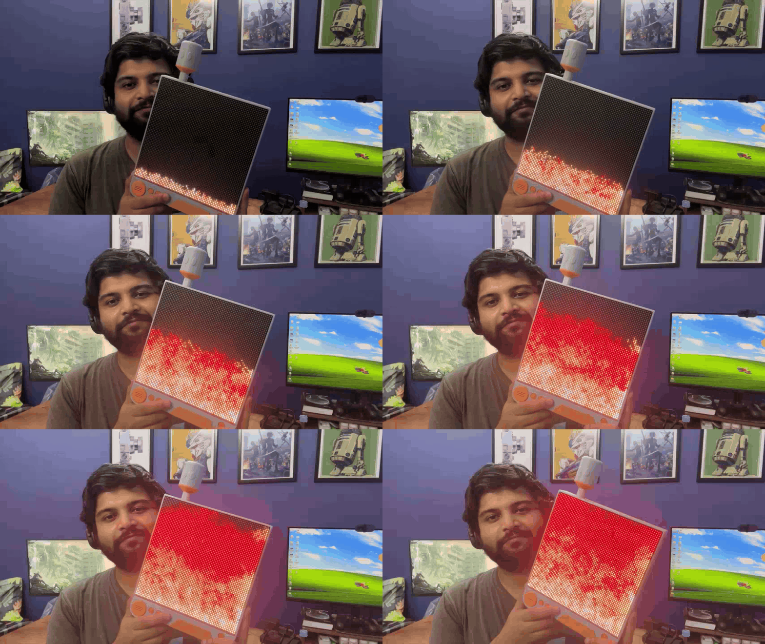
I have previously worked on a similar project called WaveForm, where I used a single 64×32 RGB matrix along with a microphone to detect surrounding sound and display an audio-reactive waveform. As the sound level increased, the waveform displayed on the matrix reacted accordingly.
I liked that feature so much that I decided to implement the WaveForm code in Project Gestalt as well.
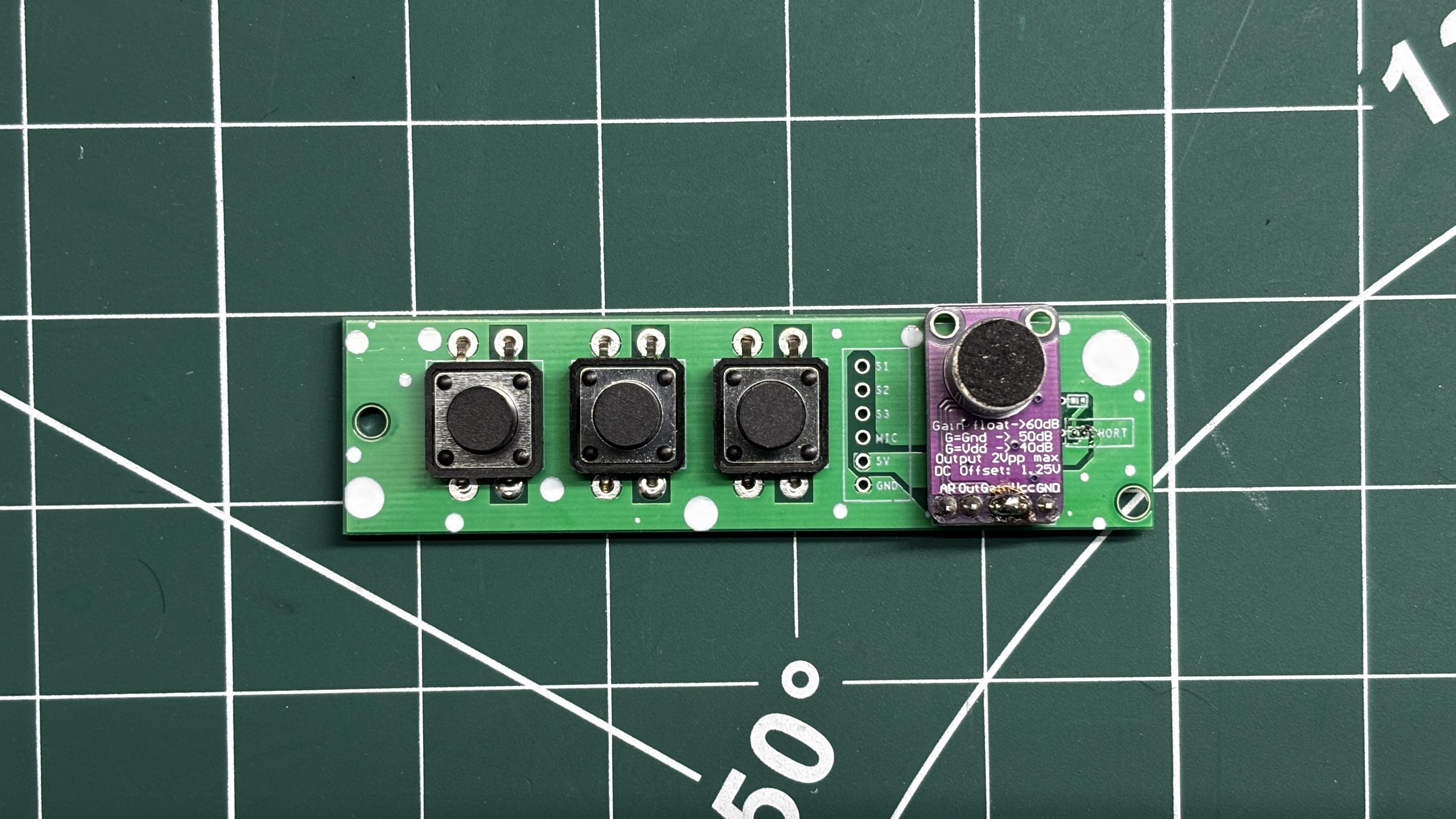
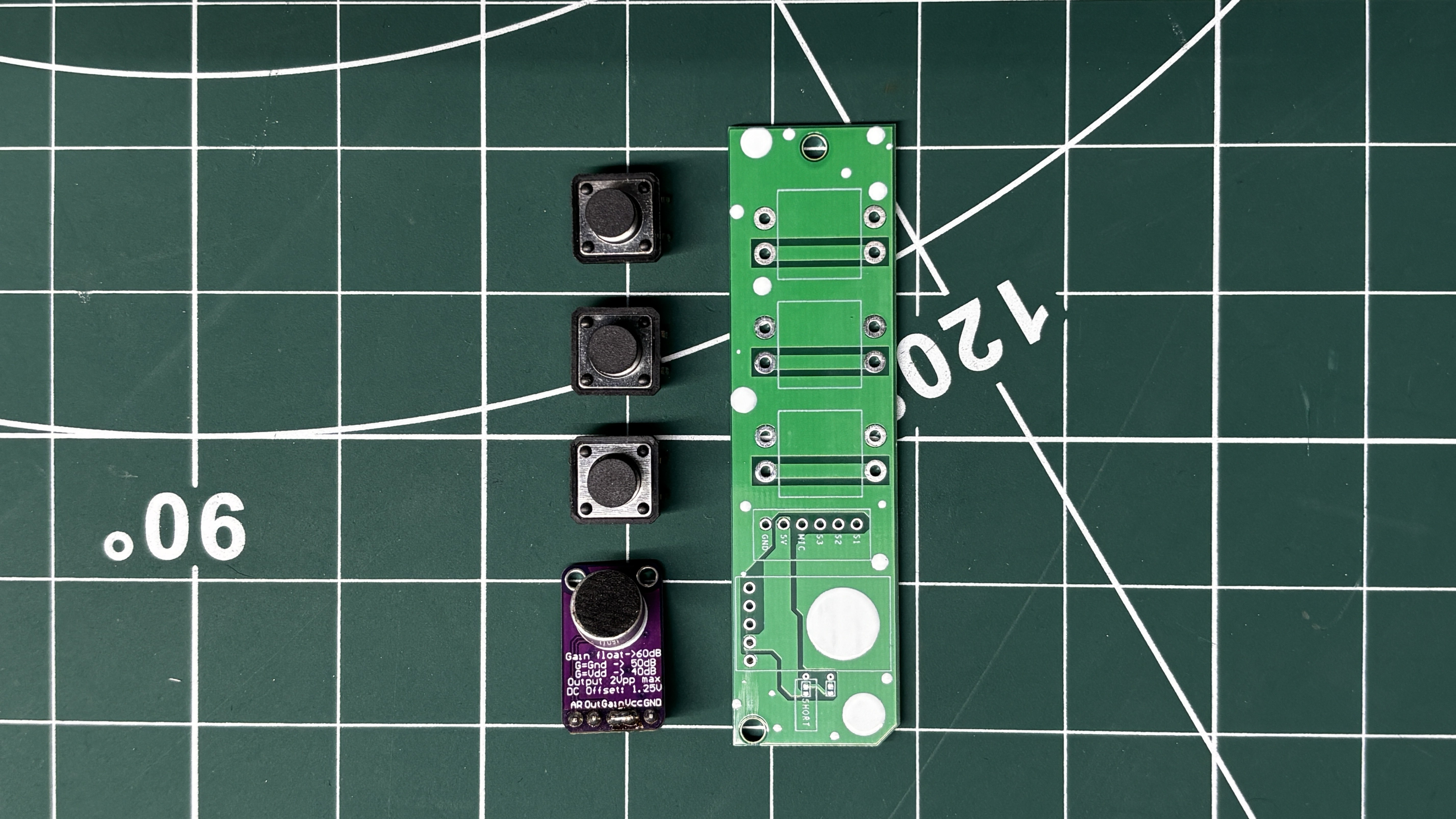
For controlling the device, I added three buttons: Previous, WaveForm, and Next. The Previous and Next buttons allow us to cycle backward and forward through the different animations stored on the device.
Pressing the WaveForm button switches the device into WaveForm mode. In this mode, the RGB matrix displays an animated waveform that reacts in real time to the sound picked up by the onboard microphone.
This Article covers the complete build process of Project Gestalt, including the enclosure design, electronics, assembly process, and code.
Let’s get started!
MATERIAL REQUIRED
These were the materials used in this project—
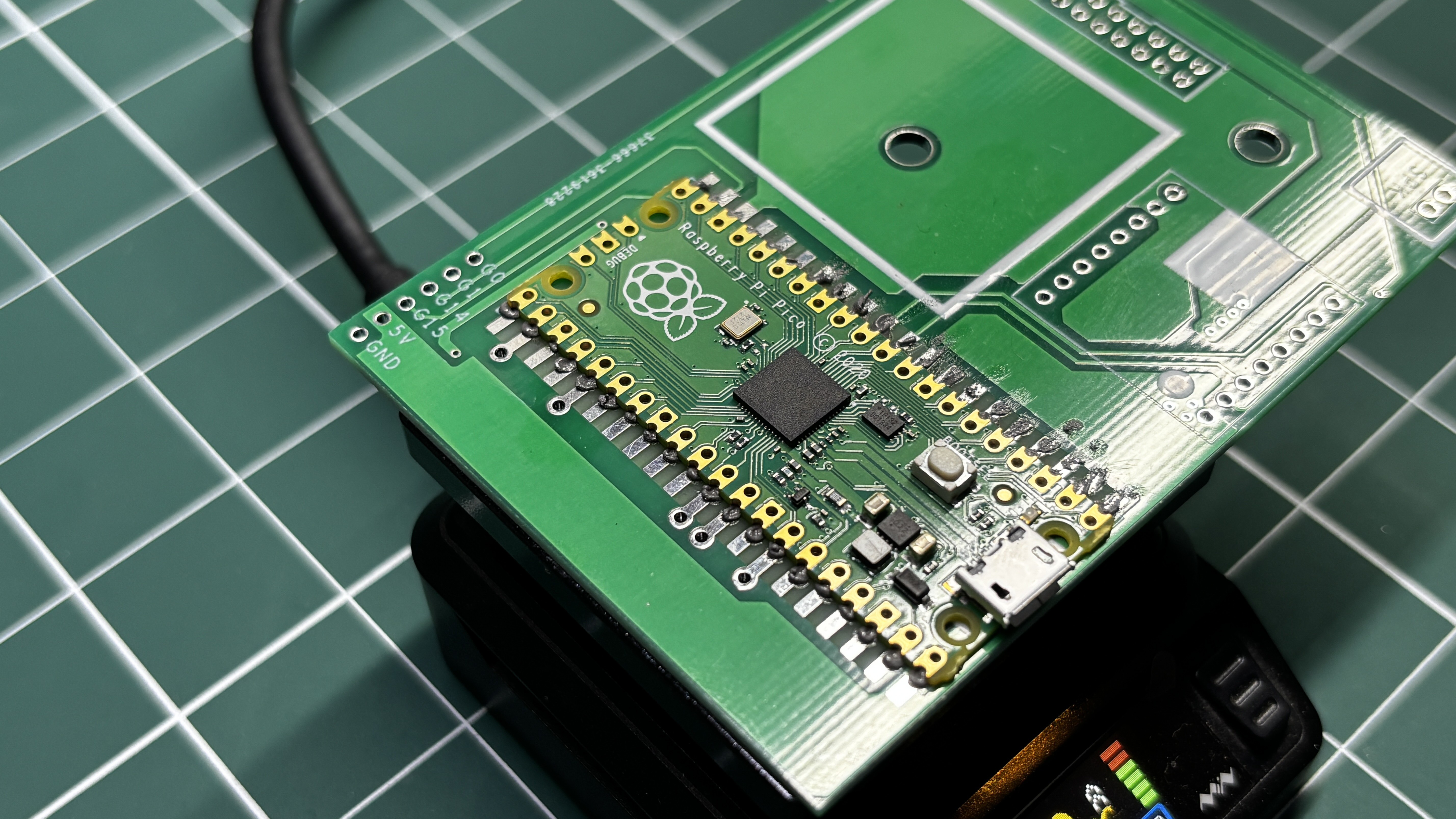
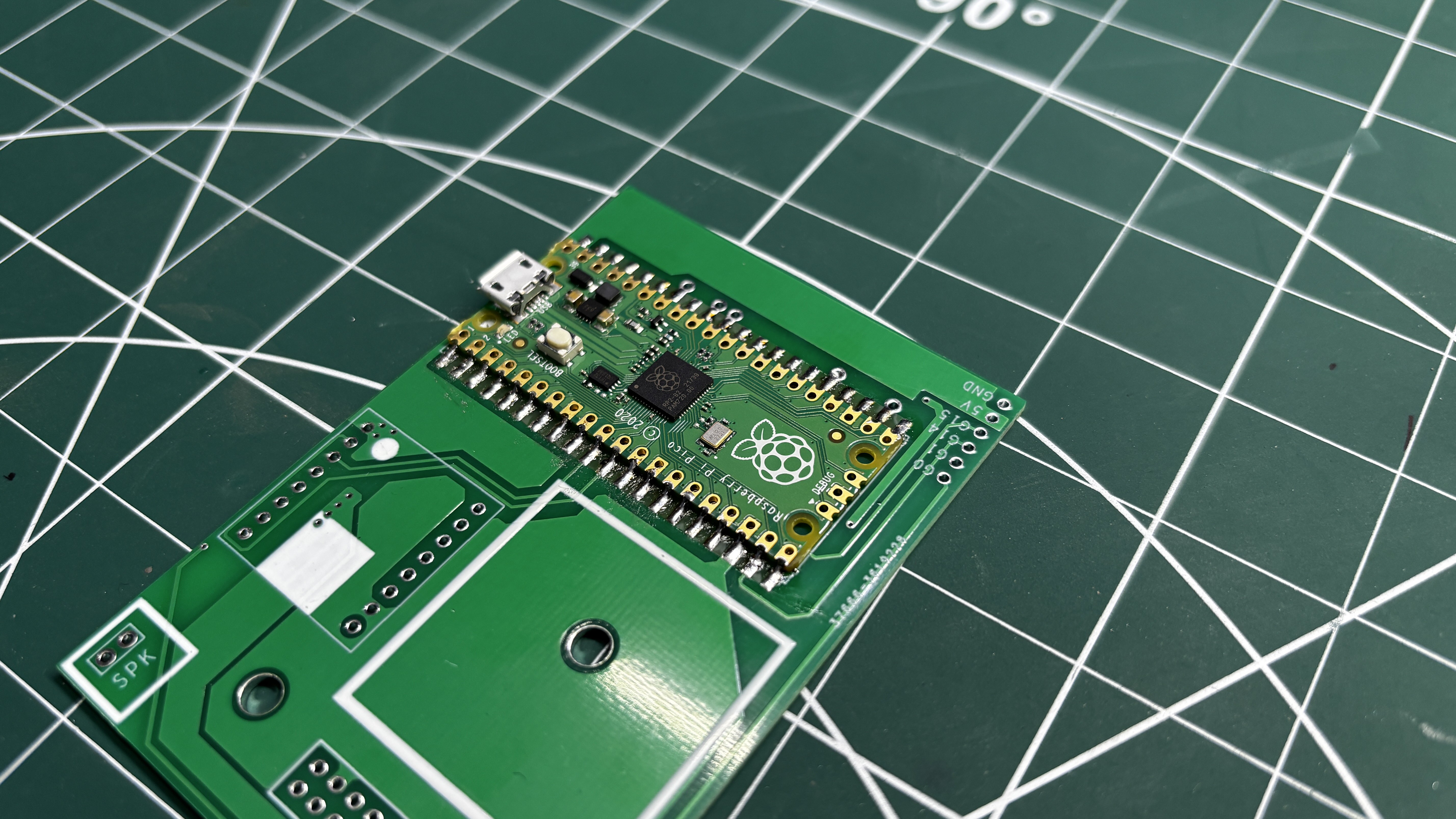
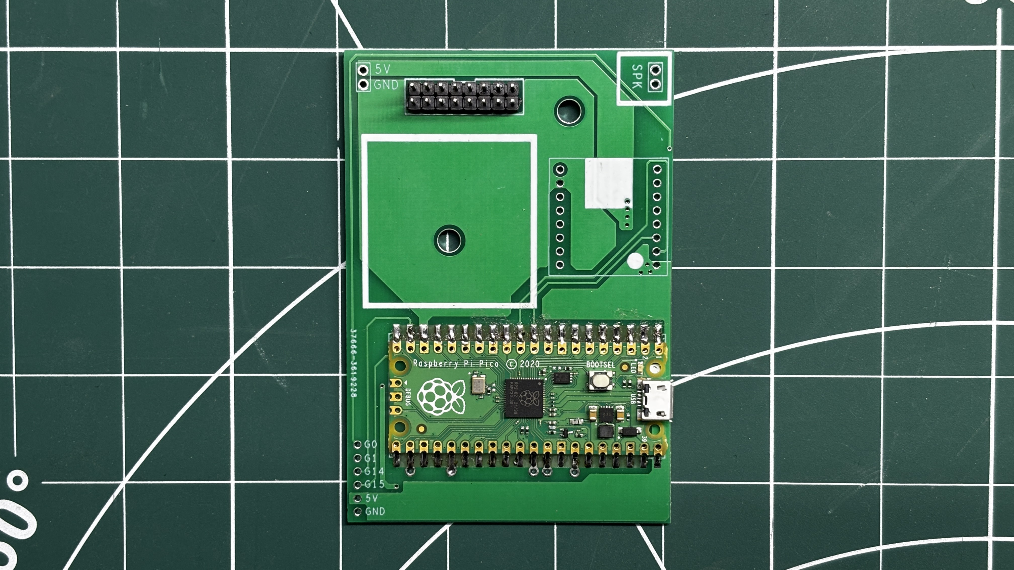
- Custom PCBs
- 64x32 P3 HUB75 RGB Matrix x 2
- Matrix Ribbon Connector
- Raspberry Pi PICO
- IP5306 Power Management IC
- 10 uF Capacitors
- 1 uH SMD Inductor
- Type C Port
- 0805 LED Indicator
- 10K Resistor: 0805 Package
- Lithium cell 3.7V 2600mAh with PCM
- Push Buttons 12x12 Size
- Push Buttons 6x6 Size
- Connecting Wires
PODS FROM NieR: AUTOMATA
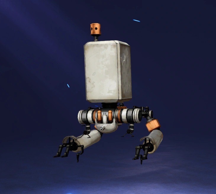

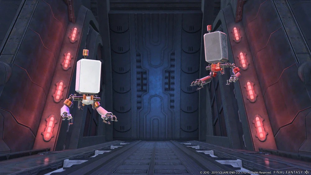
The inspiration behind this project came from PODS from NieR: Automata.
For those unfamiliar with NieR: Automata, Pods are tactical support units commonly assigned to YoRHa soldiers. They are equipped with various weapons for long-range attacks, relay messages from Command, exchange operational intelligence between units, and provide general support during missions.
Throughout most of the game, Pods appear to be emotionless machines that simply follow orders. Their dry and overly literal conversations also occasionally provide some of the funniest moments in the game. However, by the end of NieR: Automata, their role becomes much more profound. Without going too deep into spoiler territory, the Pods begin to represent something beyond their original programming, making them an unexpectedly meaningful part of the story.
As someone who really likes NieR: Automata, I had wanted to build my own Pod-inspired device for quite some time, something that I could place on my workbench as a functional piece of gaming memorabilia.
Interestingly, the RGB matrix display wasn’t actually part of the original idea. The project initially started simply as an attempt to design and build my own Pod-like device. The idea of incorporating two RGB matrices and turning it into an interactive display came later during the design process.
This eventually resulted in Project Gestalt: a device that combines the visual design of the Pods from NieR: Automata with a 64×64 RGB matrix capable of displaying animations, gaming-related visuals, random patterns, and an audio-reactive waveform.
DESIGN
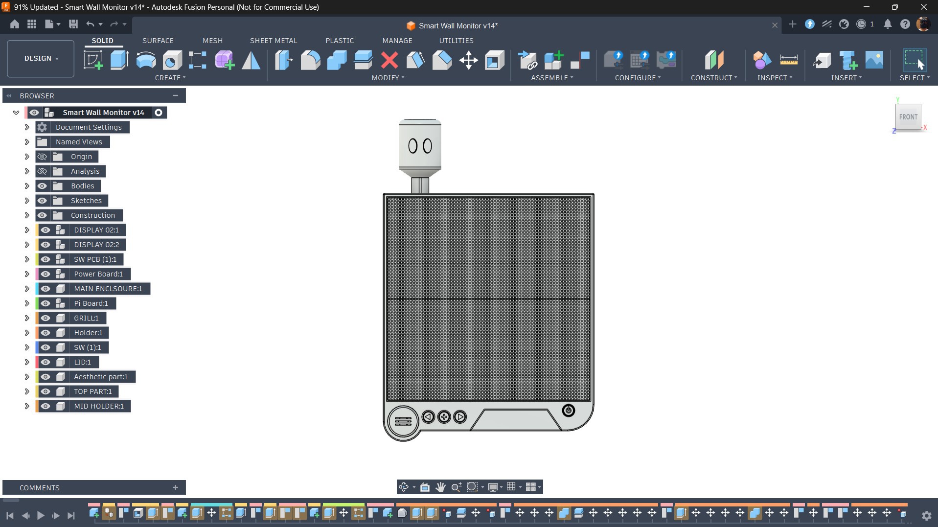
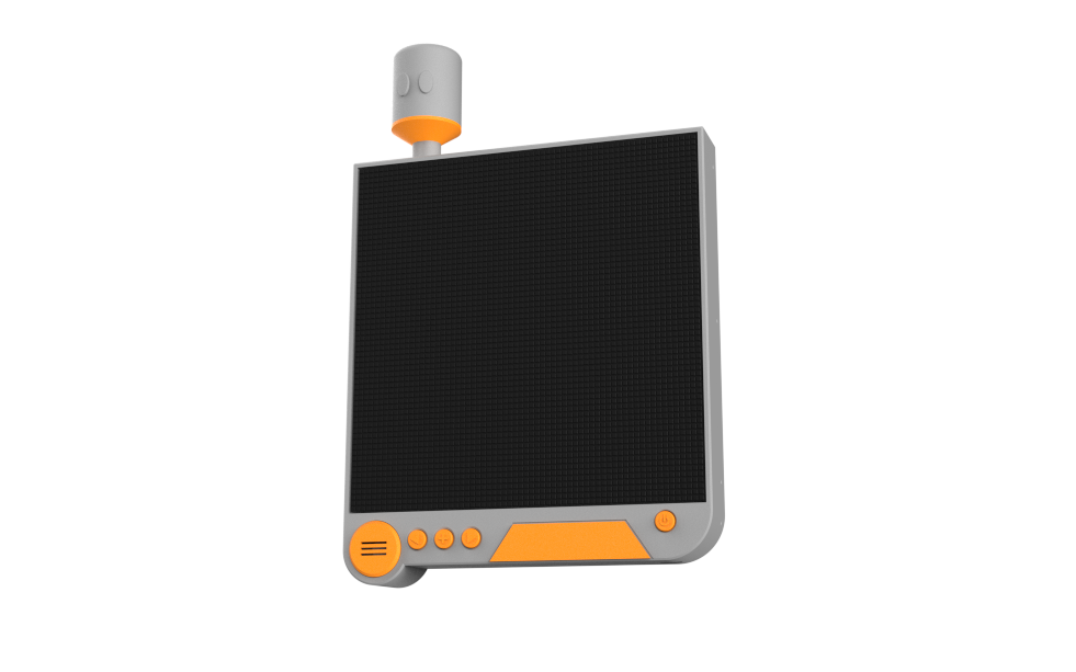
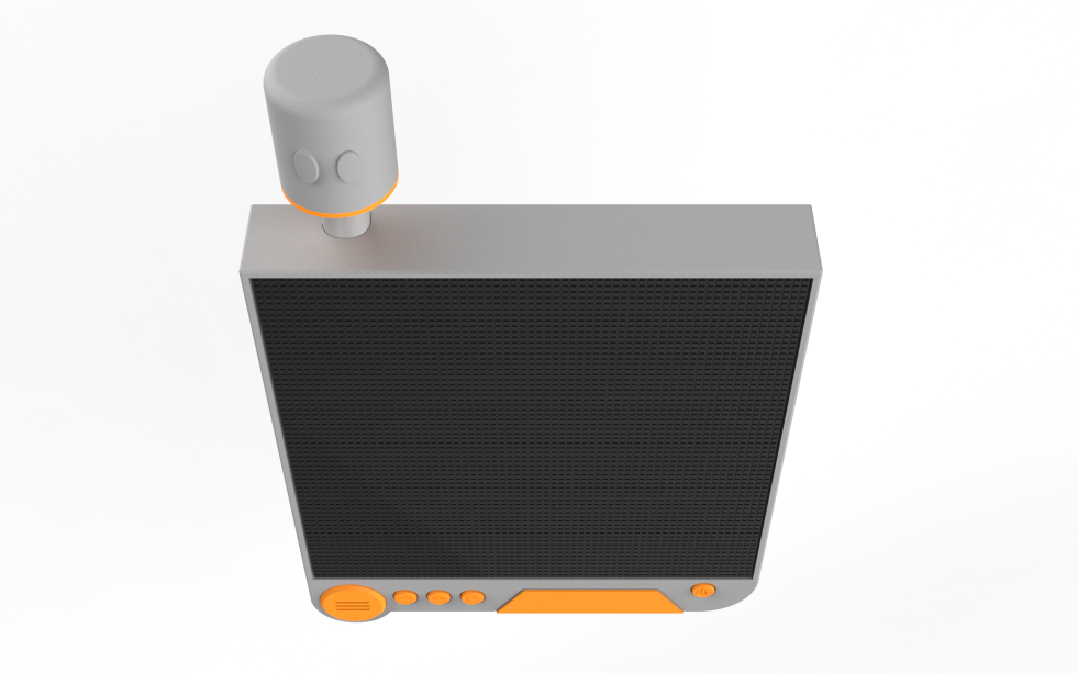
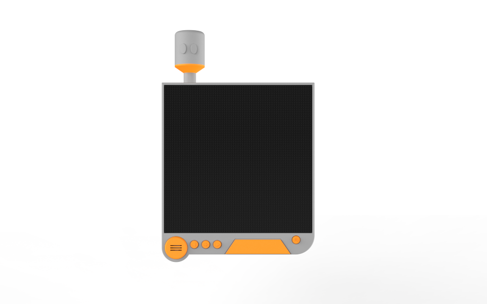
For the enclosure design of this project, my primary inspiration was the Pod from NieR: Automata, more specifically Pod 042, which is assigned to 2B. While all Pods share the same overall design, Pod 042 is distinguished by its orange accent pieces, making it instantly recognizable.
The original Pod has a fairly boxy design, whereas the RGB matrix is almost completely flat. Because of this, I couldn't create an exact replica and instead designed an enclosure that captures the overall look while accommodating the display. One feature I wanted to preserve was the cylindrical top section with its two eye-like details, which is one of the most recognizable elements of the Pod's design.
To achieve a metallic appearance, I planned to print the majority of the enclosure using grey PLA, with separate orange...
Read more »