 Alireza Noferesti
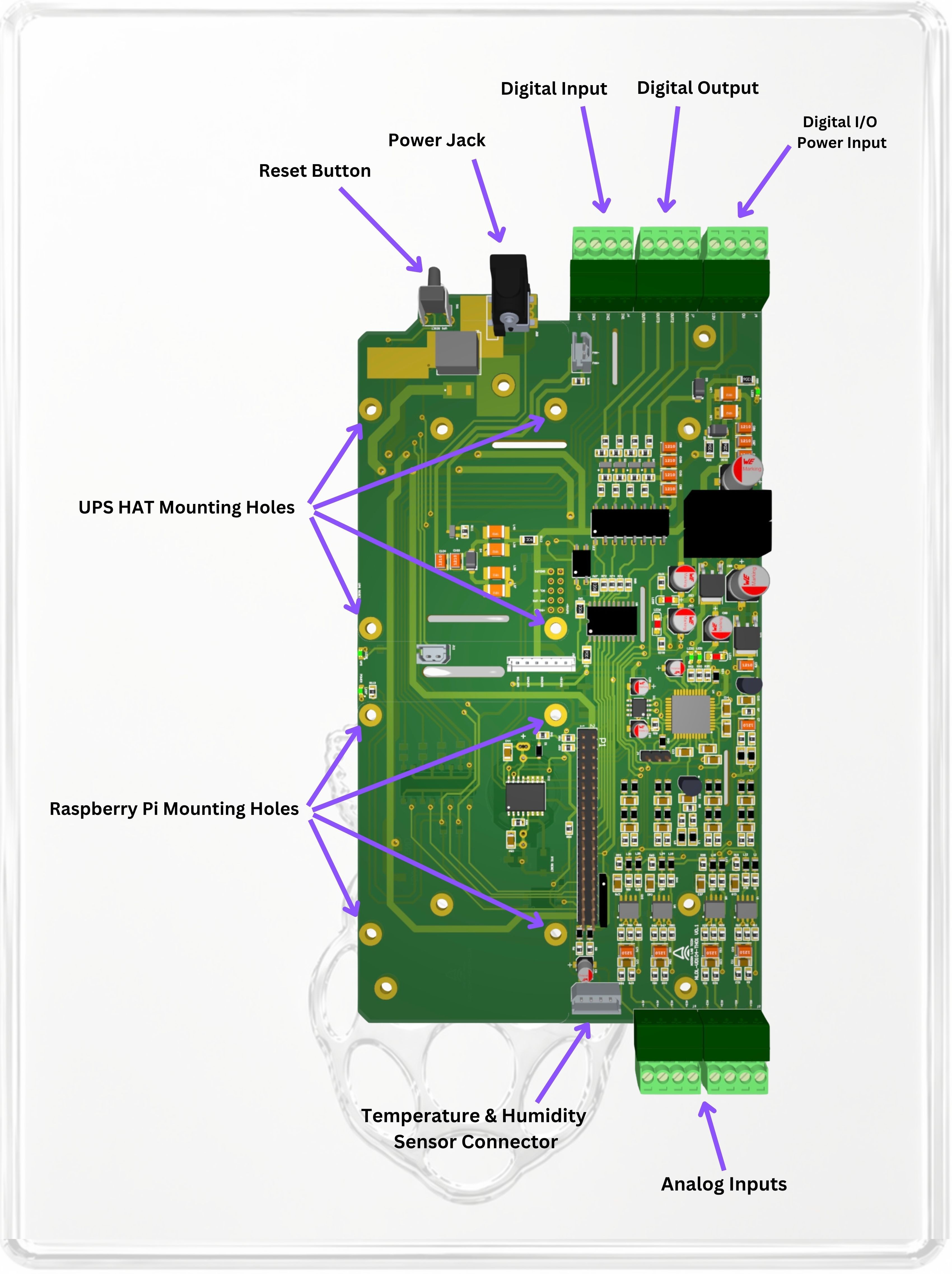
PCB Module (PCB-VD104-TH01)
Designed for Raspberry Pi users, developers, and system integrators who want to build the logger into their own enclosure, test fixture, or embedded system.
>span class="a_GcMg font-feature-liga-off font-feature-clig-off font-feature-calt-off text-decoration-none text-strikethrough-none">For applications that require uninterrupted operation, users may add a compatible UPS HAT to their Raspberry Pi setup. The UPS HAT is not included with the PCB Module, but it can be integrated to support backup power, safe shutdown, and power-loss event recording.
PCB Module Specifications
Measurement & Logging
Analog Inputs
4 differential voltage input channels
Voltage measurement range: ±0.006 V to ±12 V
12-bit differential analog inputs
Sampling rate: up to 30 kS/s per channel
Adjustable logging interval: 50 ms to 1 min
1 MΩ isolated input architecture to reduce channel-to-channel interference
Digital I/O
Digital inputs: 4
Digital outputs: 4
Logic levels: 12 V or 24 V
Output current: 50 mA per channel
Monitoring & Logging Features
Integrated temperature & humidity sensor
Independent data and error logging
Alarm history for event tracking and diagnostics
Discussions
Become a Hackaday.io Member
Create an account to leave a comment. Already have an account? Log In.