Close
0%
0%

Isolated Raspberry Pi Data Logger & DAQ Platform

Standalone DAQ with 4 differential analog inputs, 8 digital I/O, temp/humidity sensing, and a 7-inch touchscreen monitor

Public Chat
Similar projects worth following
149 views
0 followers
The Precision Data Logger is a standalone Raspberry Pi-based platform for monitoring voltage, temperature, and humidity in laboratory, engineering, and industrial applications. It features four differential voltage inputs, four digital inputs, four digital outputs, and an integrated temperature and humidity sensor. Each input channel is independently monitored and shown as a separate trace on the real-time graph.

The system continuously monitors signals and separately logs measurements, errors, and abnormal events. An optional UPS HAT with rechargeable batteries supports operation during power interruptions, power-loss logging, and controlled shutdown.

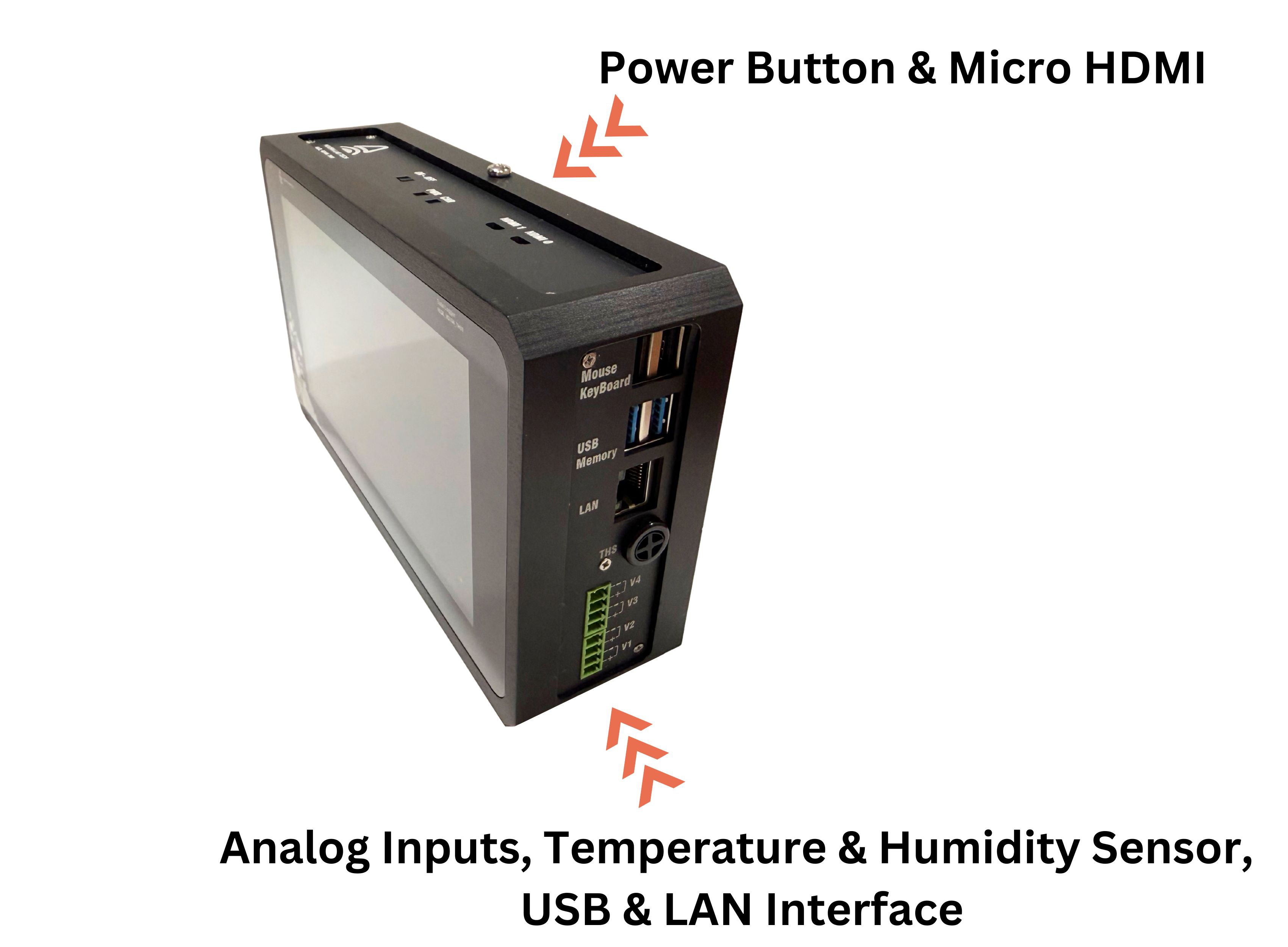
A 7-inch capacitive touchscreen enables standalone operation without a separate computer. Data can also be accessed via Wi-Fi, Ethernet, or USB. Micro-HDMI, keyboard, and mouse support desktop-style use, while internal storage, USB drives, and SSDs support extended unattended logging.

This project started with a practical requirement from a real engineering application. We needed to measure four independent voltage signals, log and store the data continuously, and display all four channels live on a graph. The system also had to continue operating during a power interruption, include a touchscreen display, and work as a completely standalone instrument without requiring a separate computer.

We decided to build the platform around a Raspberry Pi because it provides the processing power, storage, connectivity, and graphical capabilities needed for a complete data acquisition system. However, using a Raspberry Pi alone was not enough for the intended environment. We needed a dedicated PCB that could interface safely and reliably with external signals while reducing interference between measurement channels.

For this reason, we designed a custom isolated DAQ board with four differential voltage inputs, four digital inputs, four digital outputs, and an integrated temperature and humidity sensor. The internal sensor allows the system to monitor environmental conditions alongside the electrical measurements, which is especially useful in laboratory testing, equipment monitoring, and long-duration experiments.

The hardware was designed to separate the Raspberry Pi from the measurement side of the system and provide a more robust architecture for laboratory, engineering, and industrial use. Each voltage channel can be monitored independently and displayed as a separate trace on the real-time graph, allowing users to compare multiple signals during testing.

A key requirement was reliable unattended operation. The system therefore supports a UPS HAT with rechargeable batteries, allowing it to remain operational during short power interruptions, detect and record the power-loss event, and perform a controlled shutdown when necessary. Measurement data, system events, and detected errors are stored separately, making it easier to review what happened during long-duration tests.

We also needed software that could bring all parts of the system together. The complete application was developed in Qt and runs directly on the Raspberry Pi. It controls data acquisition, live graphing, digital I/O, temperature and humidity monitoring, data storage, event logging, system configuration, and the touchscreen interface.

The software was designed for operation on a 7-inch capacitive touchscreen, so the logger can be used directly without a keyboard, mouse, or external computer. The interface provides live channel values, real-time graphs, environmental readings, logging controls, storage settings, and system status in a single application. A keyboard, mouse, and external display can still be connected when desktop-style operation is preferred.

Data can be stored internally or on external USB flash drives and SSDs. The system can also be accessed through Wi-Fi, Ethernet, USB, or a remote desktop connection, giving users several options for local or remote monitoring.

What began as a solution for one four-channel measurement task gradually developed into a complete Raspberry Pi-based data acquisition platform. The project now includes the custom PCB, calibration tools, Qt-based software, touchscreen interface, communication protocols, and a complete enclosed standalone system.

More details about the device are provided below. You can also visit the Kickstarter campaign page for demonstrations, specifications, and the latest project updates.
  • Data Logger Software

    Alireza Noferesti07/16/2026 at 09:36 0 comments

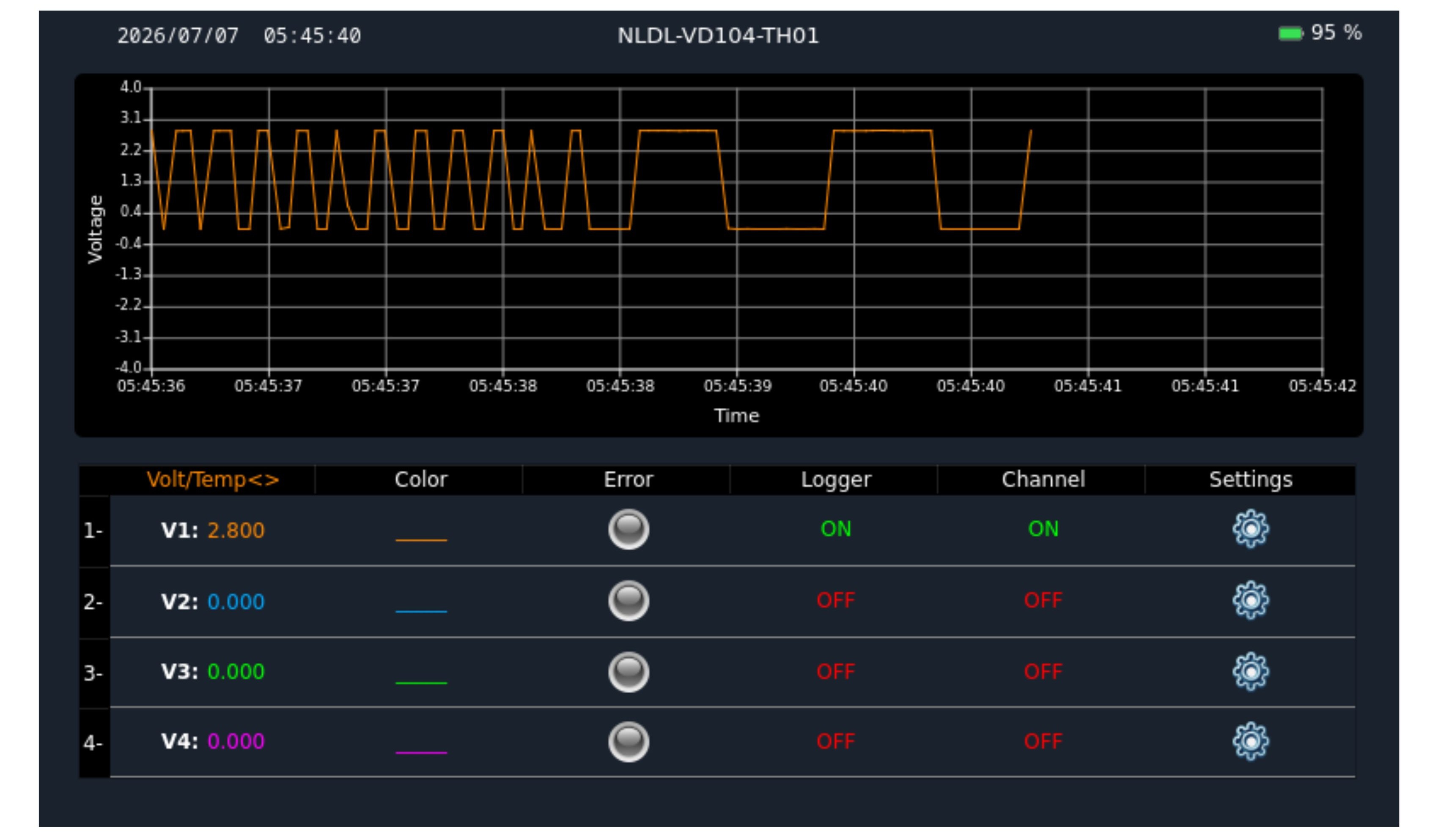
    Main Operating Screen

    After the device is powered on, the main operating screen will appear after a short startup period.

    The display is touch-enabled, allowing users to operate the device directly using their fingers. Alternatively, if a mouse is connected, all on-screen elements can also be selected and controlled using the mouse.

    1. Voltage –Time Chart

    The voltage–time chart on the main operating screen provides a real-time graphical representation of the measured voltage signals. The horizontal axis represents time, while the vertical axis displays the voltage level for each active channel.

    Each differential voltage channel is plotted simultaneously using a distinct color, allowing clear visualization and comparison of signal behavior over time. This chart enables users to quickly monitor trends, detect fluctuations, and identify abnormal conditions or transient events during operation.

    The chart is continuously updated based on the selected logging and sampling settings, providing immediate visual feedback of system performance and measurement stability.

    2. Battery Status Indicator

    The battery status indicator shows the current battery charge level. When the power adapter is connected, a yellow indicator appears on the battery display.

    3. Date & Time Display

    This display shows the current system date and time, which are used for time-stamping logged data and recorded events.

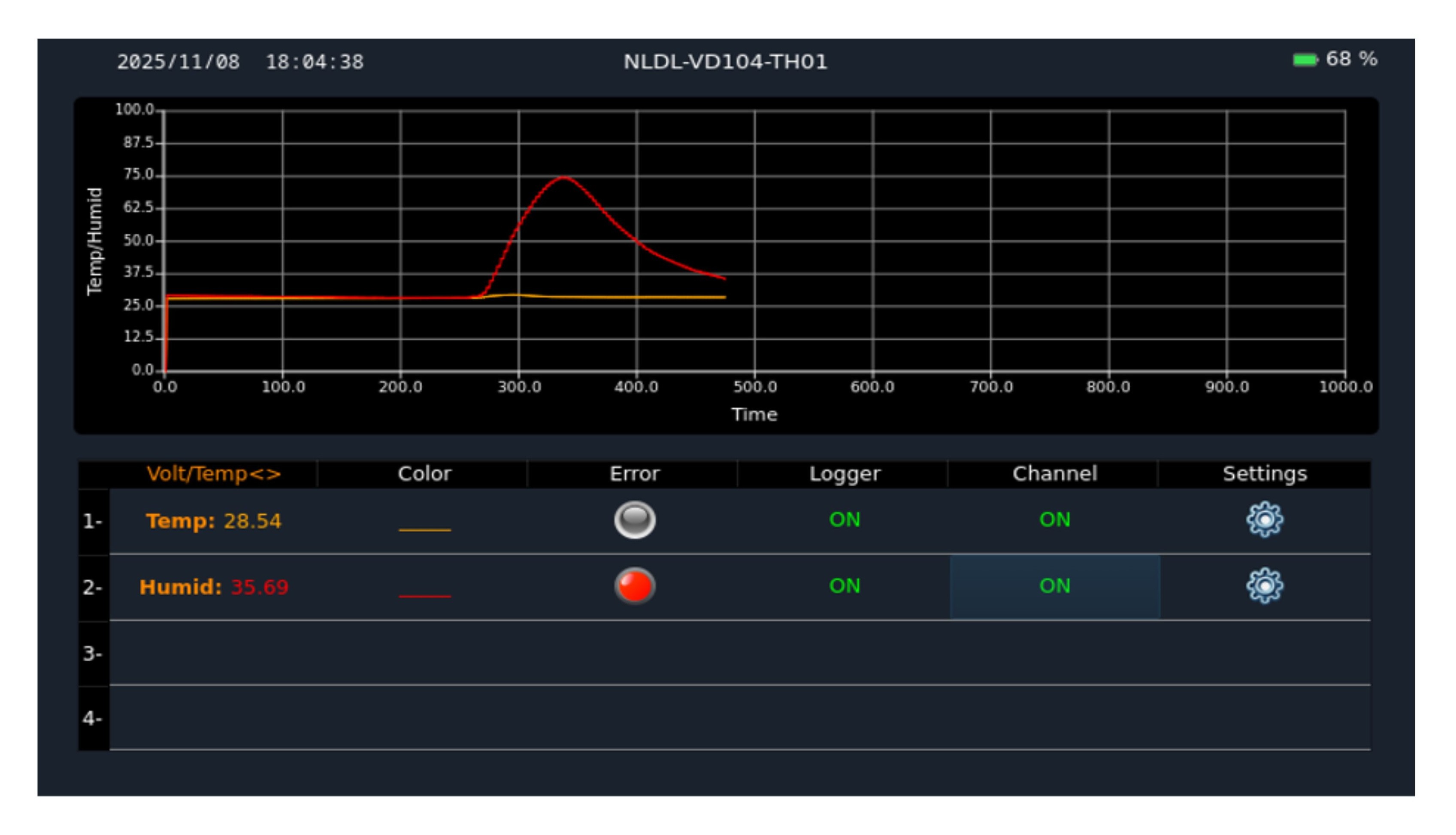
    4. Volt/Temp Button

    By default, the main screen shows voltage measurements. Pressing the Volt/Temp button toggles the display between the voltage view and the temperature & humidity view.

    Color Button

    The Color column shows the current chart color for each channel. 

    Selecting a row opens the color selection screen, where a new color can be assigned to the channel.

    Error Indicators

    The ERROR column shows the error status for each channel. When an error occurs, the indicator activates and can be cleared by selecting it. Errors remain stored in memory until manually cleared, even after power-off.

    Logger Buttons

    This control allows the user to turn data logging on or off for each individual channel.

    Channel Buttons

    This control allows the user to enable or disable the chart display for each individual channel.

    Setting Buttons

    Clicking the buttons in this column allows access to the configuration settings for each individual channel.

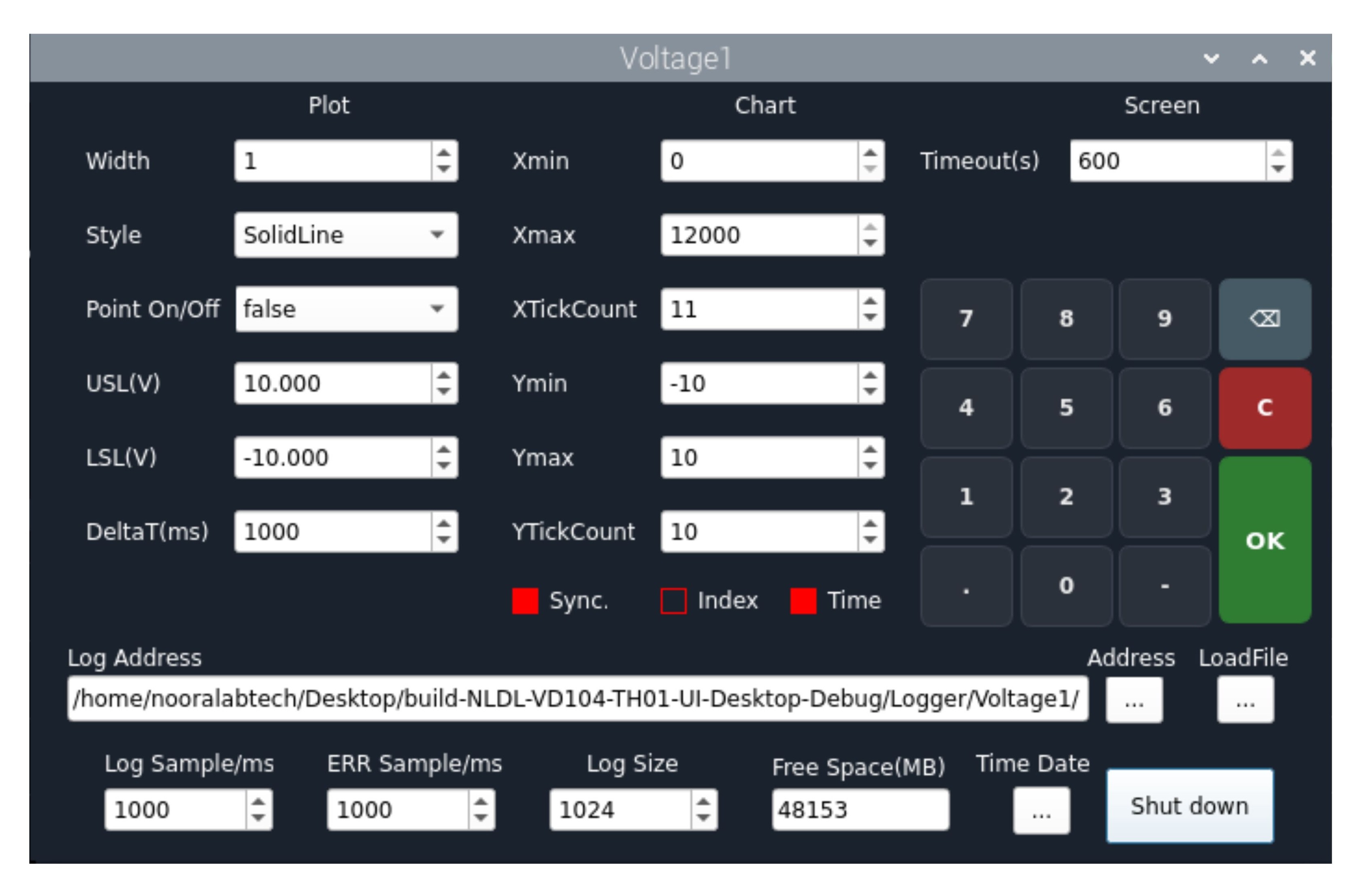
    When the channel settings button is selected, the window shown below will open, allowing each channel to be configured individually and separately from the others.

    Plot

    This section allows you to adjust the chart display characteristics for each individual channel.

    Width

    Used to adjust the line thickness of the plotted chart.

    Style

    Used to select the display style of the plotted line on the chart.

    NoPen: Enables point-only display mode. After selecting NoPen, set Point On/Off to True to make the points visible.

    SolidLine: Displays the plotted line in a continuous solid style. (—)

    DashLine: Displays the plotted line in a dashed style. (---)

    DotLine: Displays the plotted line in a dotted style. (...)

    DashDotLine: Displays the plotted line in a dash-dot pattern. (-.-.-)

    DashDotDotLine: Displays the plotted line in a dash-dot-dot pattern. (-..-)

    Point On/Off

    When this option is set to True, the intersection point of each X and Y data sample will be displayed as dots on the chart. Set to False to hide the points.

    USL(V) / (C)

    Enter the upper threshold value for the error-detection system. The value is specified in volts (V) for voltage channels and in degrees Celsius (°C) for temperature measurements.

    LSL(V) / (C)

    Enter the lower threshold value for the error-detection system. The value is specified in volts (V) for voltage channels and in degrees Celsius (°C) for temperature measurements.

    DeltaT(ms)

    Specifies the sampling interval (time per data point) on the chart in milliseconds.

    Chart

    Here you can configure the...

    Read more »

  • PCB Module

    Alireza Noferesti07/15/2026 at 14:08 0 comments

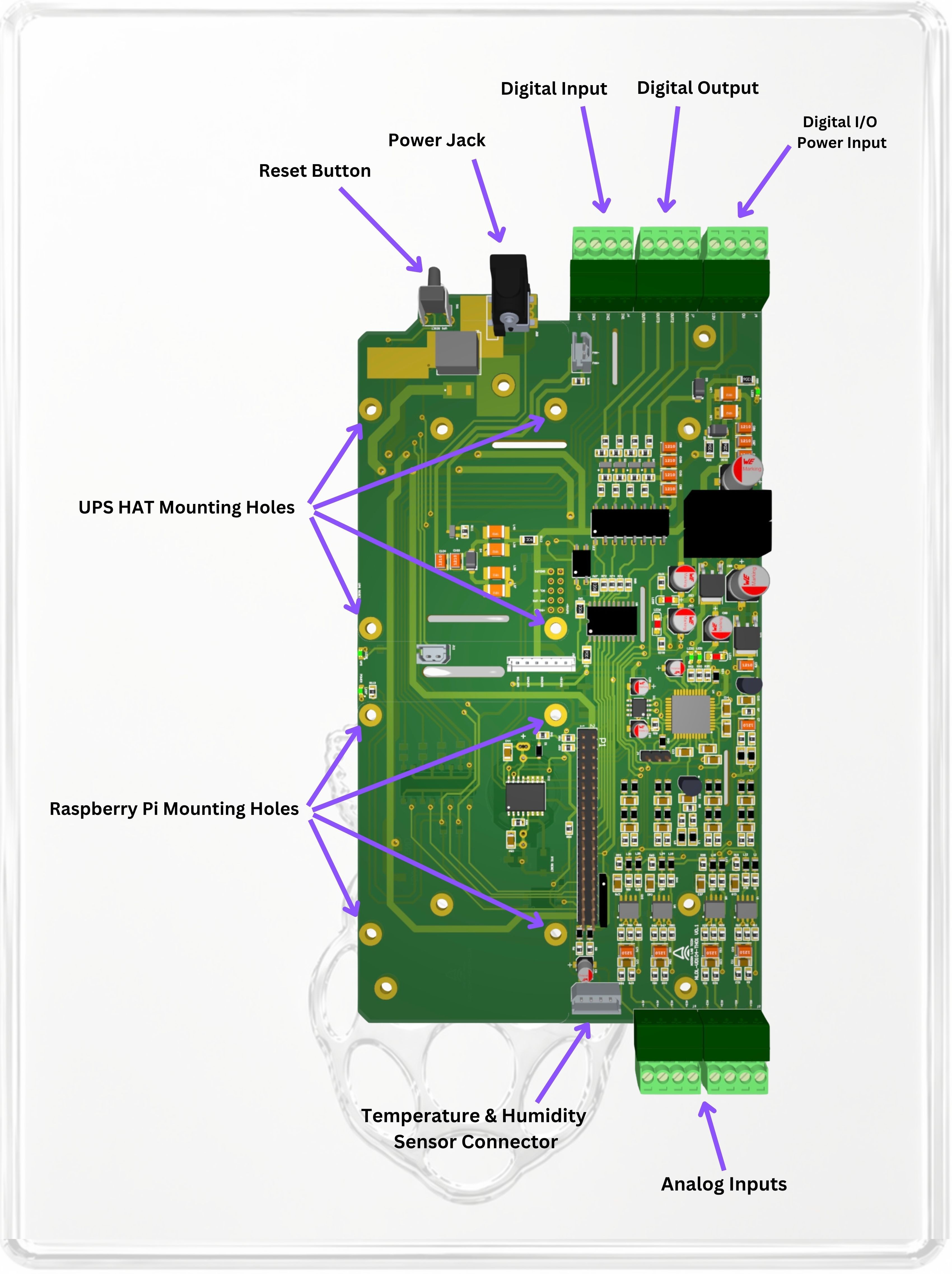
    PCB Module (PCB-VD104-TH01)

    Designed for Raspberry Pi users, developers, and system integrators who want to build the logger into their own enclosure, test fixture, or embedded system.

    >span class="a_GcMg font-feature-liga-off font-feature-clig-off font-feature-calt-off text-decoration-none text-strikethrough-none">For applications that require uninterrupted operation, users may add a compatible UPS HAT to their Raspberry Pi setup. The UPS HAT is not included with the PCB Module, but it can be integrated to support backup power, safe shutdown, and power-loss event recording.

    PCB Module Specifications

    Measurement & Logging

    Analog Inputs

    4 differential voltage input channels

    Voltage measurement range: ±0.006 V to ±12 V

    12-bit differential analog inputs

    Sampling rate: up to 30 kS/s per channel

    Adjustable logging interval: 50 ms to 1 min

    1 MΩ isolated input architecture to reduce channel-to-channel interference

    Digital I/O

    Digital inputs: 4

    Digital outputs: 4

    Logic levels: 12 V or 24 V

    Output current: 50 mA per channel

    Monitoring & Logging Features

    Integrated temperature & humidity sensor

    Independent data and error logging

    Alarm history for event tracking and diagnostics

  • Complete Enclosed Logger

    Alireza Noferesti07/15/2026 at 13:55 0 comments

    Complete Enclosed Logger (NLDL-VD104-TH01)

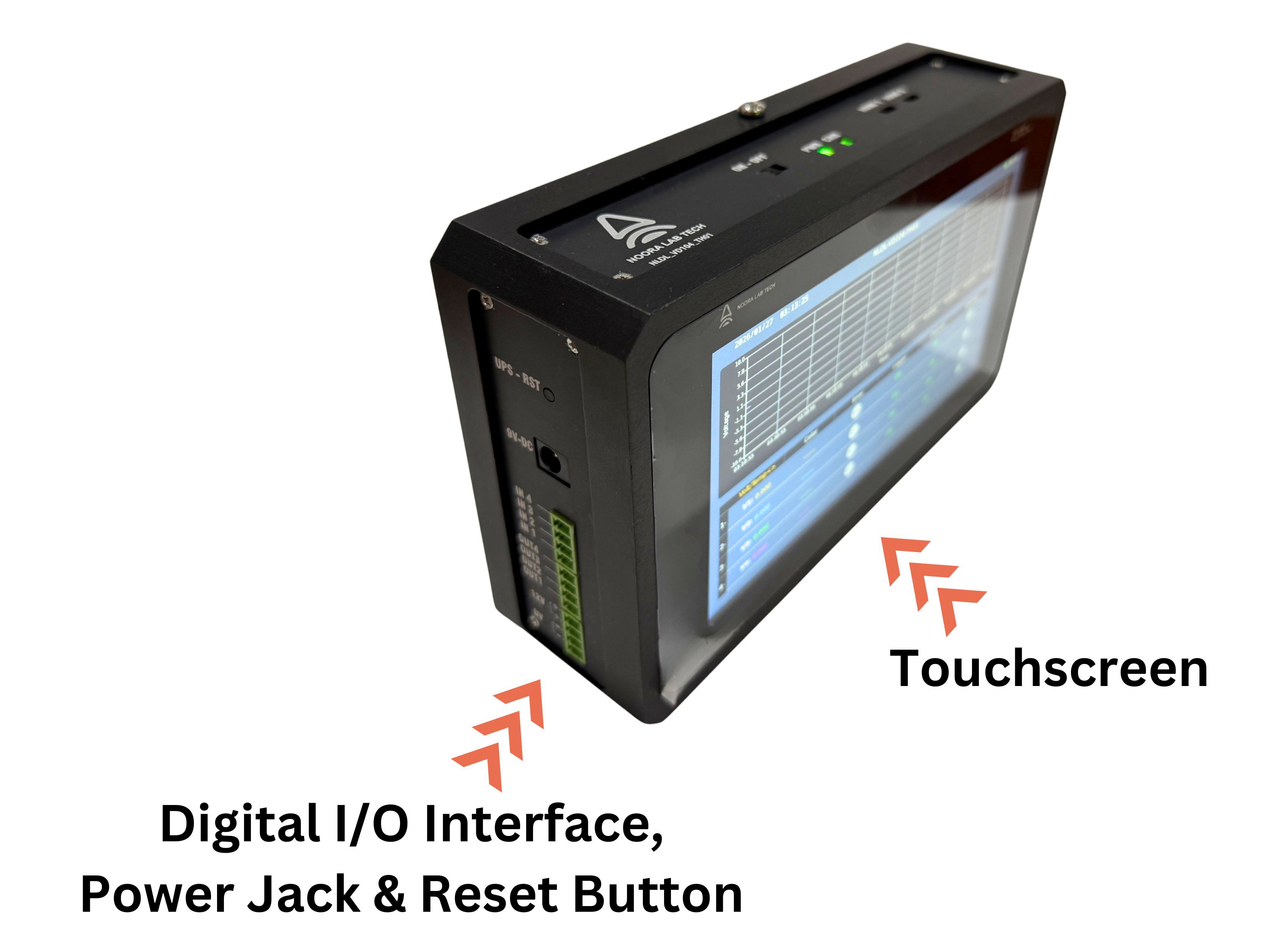
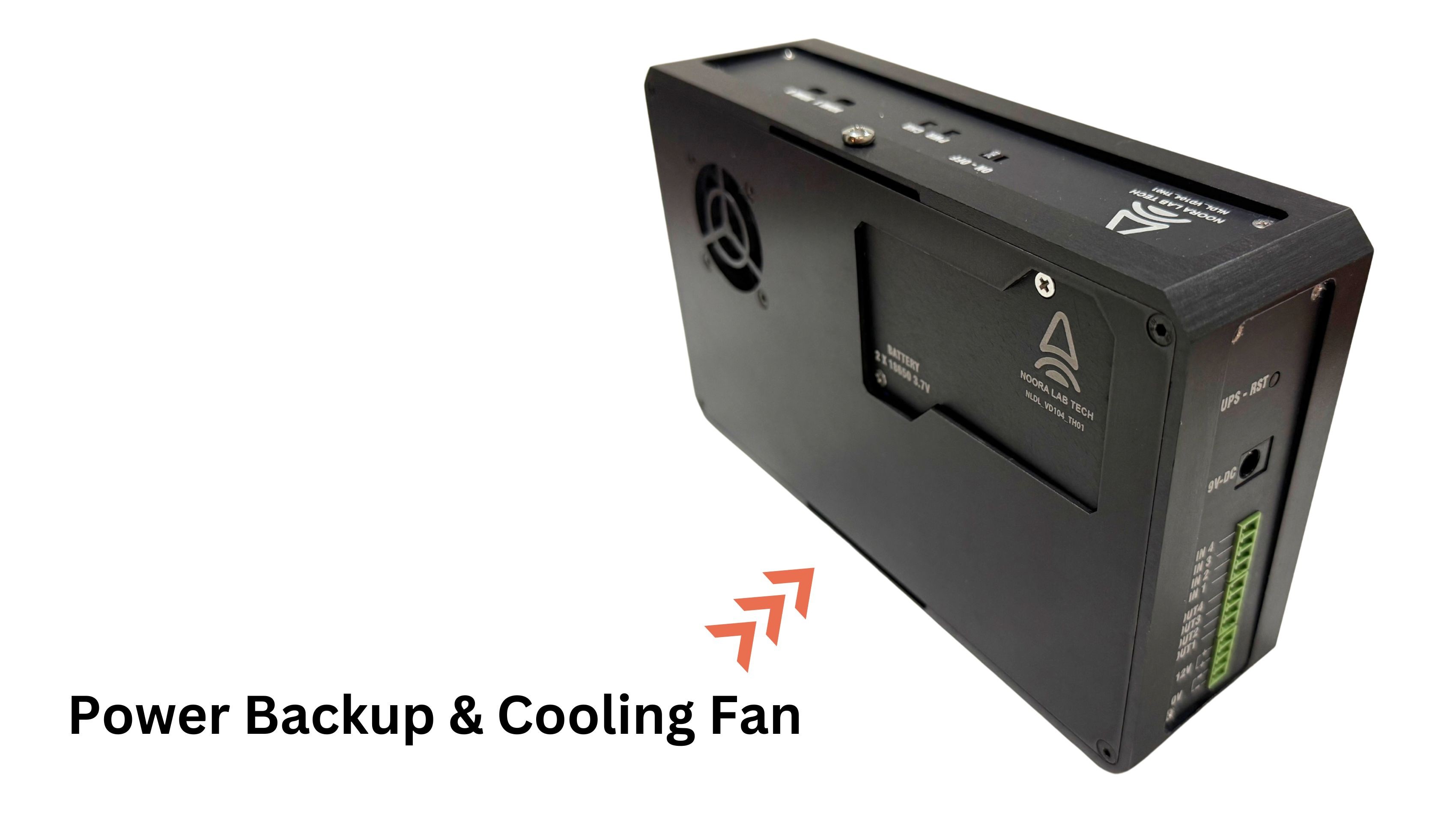
    A ready-to-use instrument including the logger PCB, Raspberry Pi, 7-inch touchscreen display, UPS HAT, and durable metal enclosure. The built-in UPS HAT supports two 3,500 mAh 18650 lithium batteries for backup power. Batteries are not included to simplify shipping and avoid lithium battery transport restrictions, allowing users to source and install compatible cells locally.

    Complete Enclosed Logger Specifications

    Measurement & Logging

    Analog Inputs

    4 differential voltage input channels

    Voltage measurement range: ±0.006 V to ±12 V

    12-bit differential analog inputs

    Sampling rate: up to 30 kS/s per channel

    Adjustable logging interval: 50 ms to 1 min

    1 MΩ isolated input architecture to reduce channel-to-channel interference

    Digital I/O

    Digital inputs: 4

    Digital outputs: 4

    Logic levels: 12 V or 24 V

    Output current: 50 mA per channel

    Monitoring & Logging Features

    Integrated temperature & humidity sensor

    Independent data and error logging

    Alarm history for event tracking and diagnostics

    Connectivity & Interfaces

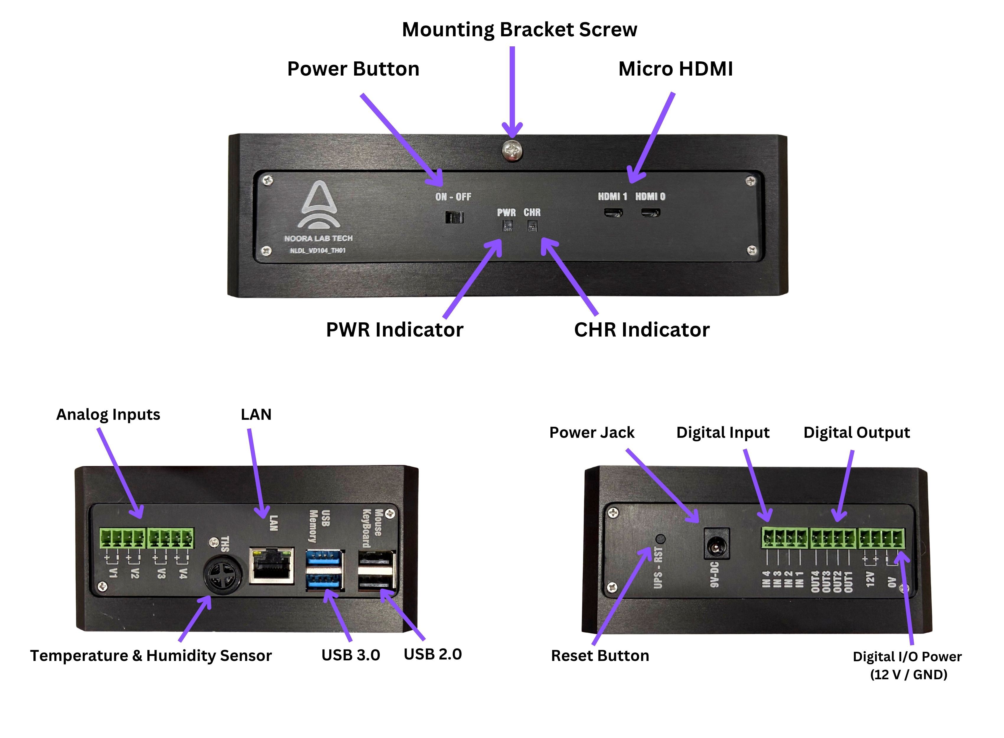
    • LAN and Wi-Fi connectivity
    • VNC remote screen access
    • 2 × USB 2.0 ports
    • 2 × USB 3.0 ports
    • Dual Micro HDMI outputs

    Temperature & Humidity

    • Temperature accuracy: ±0.54 °F / ±0.3 °C
    • Temperature measurement range: –40 °F to +257 °F / –40 °C to +125 °C
    • Humidity operating range: 0 to 100 %RH
    • Humidity accuracy: ±3 %RH

    For applications requiring higher temperature measurement accuracy, the NLDL-VD104-TH01E model will be available as an option after the campaign ends. This version includes an external temperature probe mounted away from the device housing to minimize the influence of internal heat.

    Storage & Data Security

    • Internal storage options: 64 GB, 128 GB, 256 GB
    • External storage support: USB flash drives and external SSDs up to 2 TB

    Automatic storage failover: uninterrupted logging during external storage removal, with automatic switching to internal memory if external storage is removed or unavailable

    Power System

    Integrated UPS HAT

    Supports two 3,500 mAh 18650 lithium batteries 

    Up to 3 hours of continuous operation, depending on battery quality, system configuration, and connected peripherals

    Automatic transition between external power and battery operation

    Mechanical Specifications

    Durable aluminum enclosure

    Dimensions: 8.15 × 4.92 × 2.28 in / 207 × 125 × 58 mm

View all 3 project logs

Enjoy this project?

Share

Discussions

Similar Projects

Does this project spark your interest?

Become a member to follow this project and never miss any updates