 youkito1991
-
1Overview
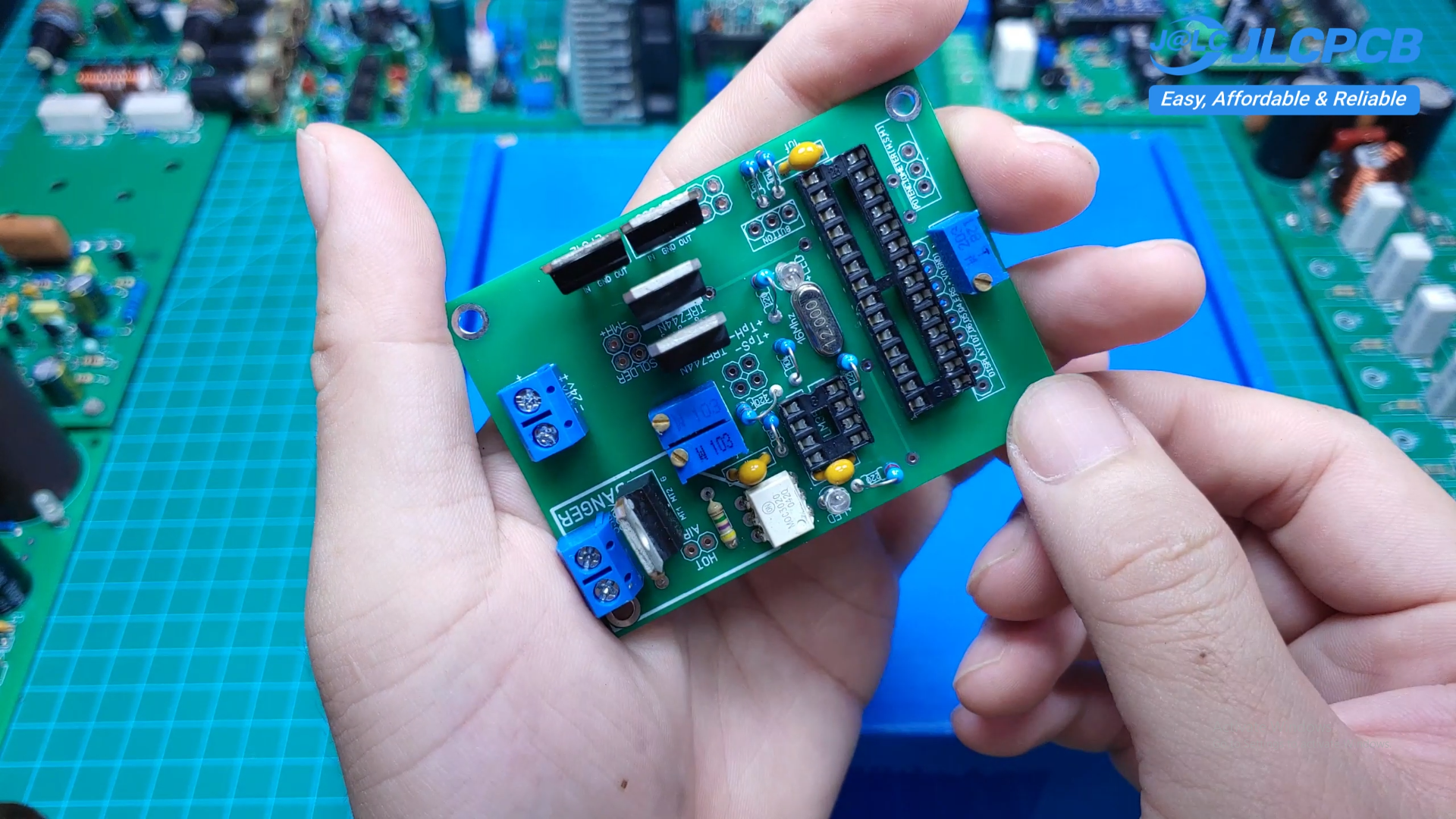
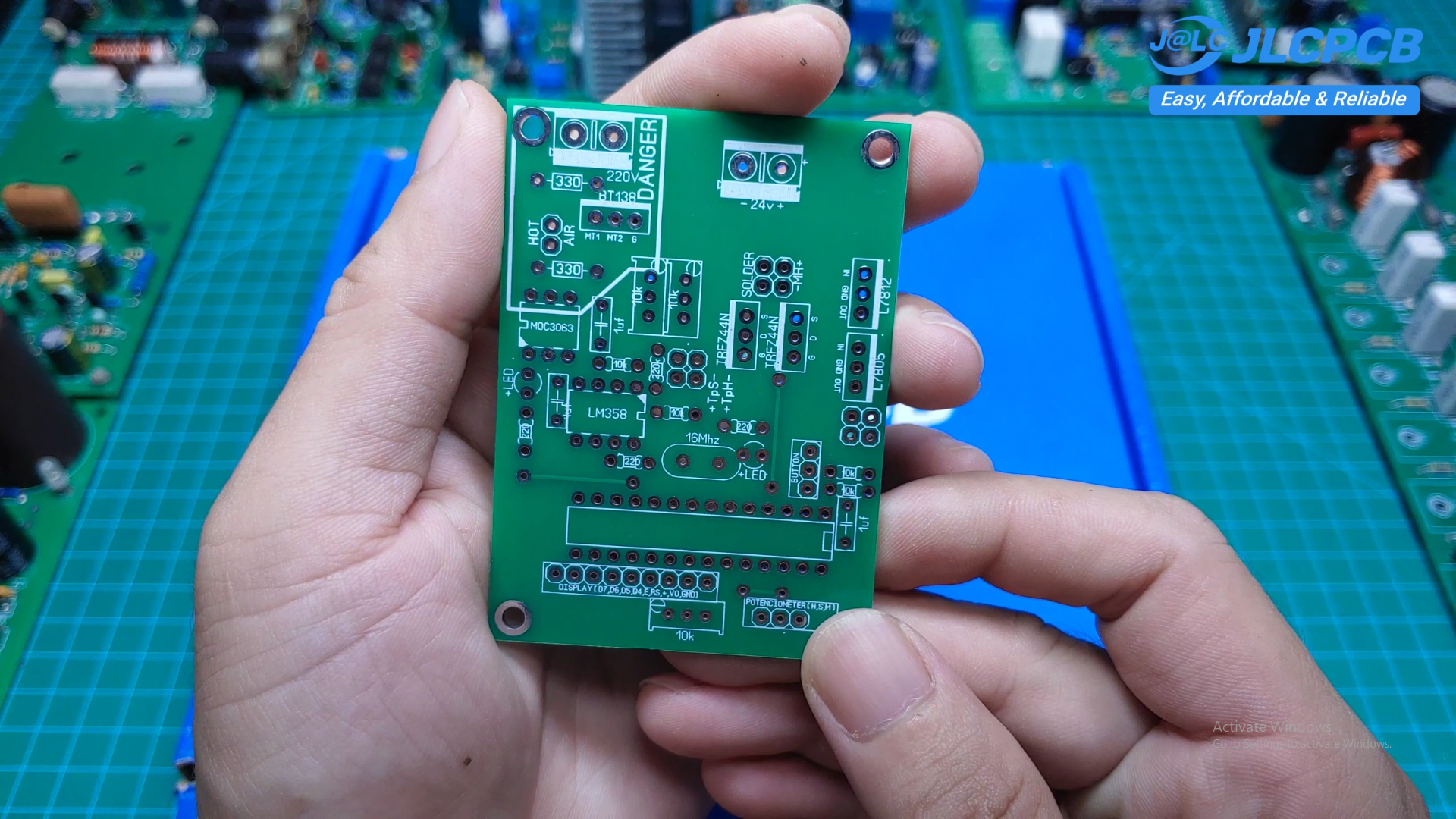
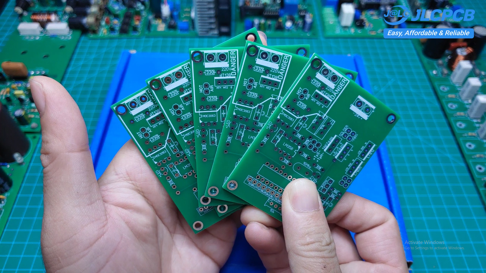
After using several commercial soldering stations over the years, I decided to build my own integrated soldering station and hot air rework station. The main objective was to create a reliable, feature-rich, and affordable tool suitable for electronics repair, PCB assembly, and everyday bench work. The PCB order from JLCPCB
The entire system is built around an ATmega microcontroller, which manages temperature control, the user interface, safety features, and system monitoring. Instead of designing two separate controllers, both the soldering iron and hot air station are integrated into a single unit with a common interface.
The project has been tested extensively during real repair work and has proven to be stable, accurate, and easy to use.
-
2Design Goals
![]()
![]()
![]()
The project was designed with several objectives in mind:
- Professional temperature stability
- Fast heating response
- Accurate PID temperature control
- Simple and intuitive user interface
- Long-term reliability
- Low manufacturing cost
- Easy maintenance and future upgrades
-
3Main Features
![]()
- ATmega microcontroller
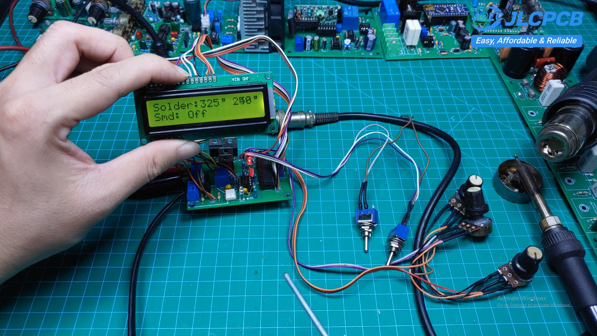
- LCD user interface
- Rotary encoder navigation
- Independent control of soldering iron and hot air gun
- PID temperature control
- Adjustable temperature settings
- Automatic sleep mode for the soldering iron
- Automatic standby mode for the hot air gun
- Cooling cycle after heater shutdown
- Temperature calibration
- EEPROM parameter storage
- Audible feedback
- Multiple protection functions
-
4Hardware
![]()
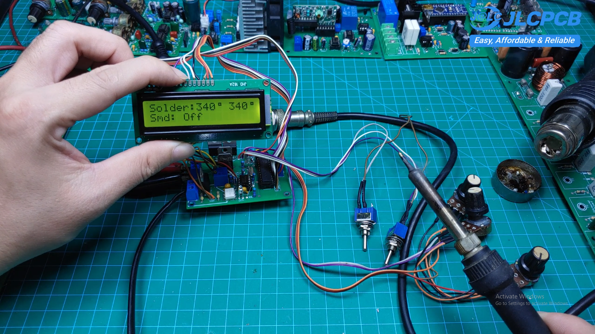
The controller consists of several functional blocks:
- ATmega microcontroller
- LCD display
- Rotary encoder
- Temperature amplifier circuit
- Heater driver circuit
- Fan control circuit
- Power supply
- Buzzer
- Power management circuitry
Care was taken to minimize electrical noise around the temperature sensing circuits to improve measurement accuracy and overall control stability.
-
5Firmware
The firmware continuously monitors the temperature sensors and adjusts heater power using a PID control algorithm.
Several operating modes are implemented:
- Normal operation
- Sleep mode
- Standby mode
- Temperature calibration
- Configuration menu
- Error detection
The software is written to be modular, making future upgrades straightforward.
-
6Temperature Control
One of the most important goals of this project was achieving stable temperature regulation.
The PID controller allows the station to:
- Heat up quickly
- Minimize overshoot
- Recover rapidly after soldering large copper areas
- Maintain a stable working temperature
This results in a much better soldering experience than simple on/off control.
-
7Hot Air Station
![]()
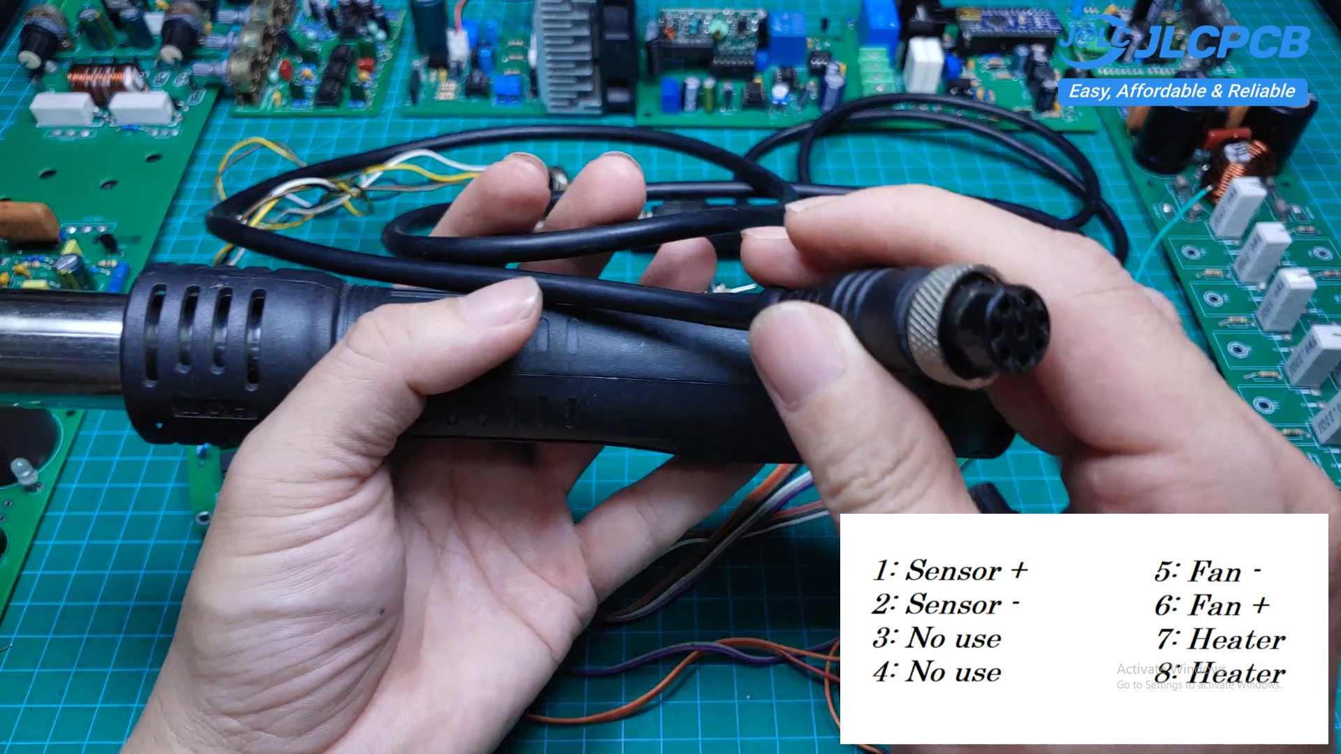
The hot air section includes several safety features.
When the handle is returned to its holder, the heater is automatically turned off while the fan continues running to cool the heating element. This significantly extends the heater's lifespan and improves operational safety
-
8User Interface
The LCD and rotary encoder provide a simple but effective interface.
Users can easily:
- Adjust soldering temperature
- Adjust hot air temperature
- Configure sleep timeout
- Calibrate temperature readings
- Save settings to EEPROM
All settings are retained after power loss.
-
9Project Status
The hardware has been completed and fully assembled.
Current testing includes:
- Long-term temperature stability
- Continuous operation
- Heating performance
- User interface optimization
So far, the system has been operating reliably with excellent temperature control.
-
10Build Resources
The complete project includes:
- Schematic
- PCB design
- Firmware
- Bill of Materials (BOM)
- Assembly guide
- Demonstration video
These resources are intended to help other makers reproduce or further improve the design.
DIY Digital Soldering & Hot Air Rework Station
I will show you how to build a complete digital soldering and hot-air rework station using an Atmega microcontroller.
Discussions
Become a Hackaday.io Member
Create an account to leave a comment. Already have an account? Log In.