iliasam
-
OpenSimpleLidar calibration
05/26/2019 at 15:26 • 0 commentsOpenSimpleLidar need calibration after assembling so I had made a video about it:
-
Published PC utility for Lidar testing
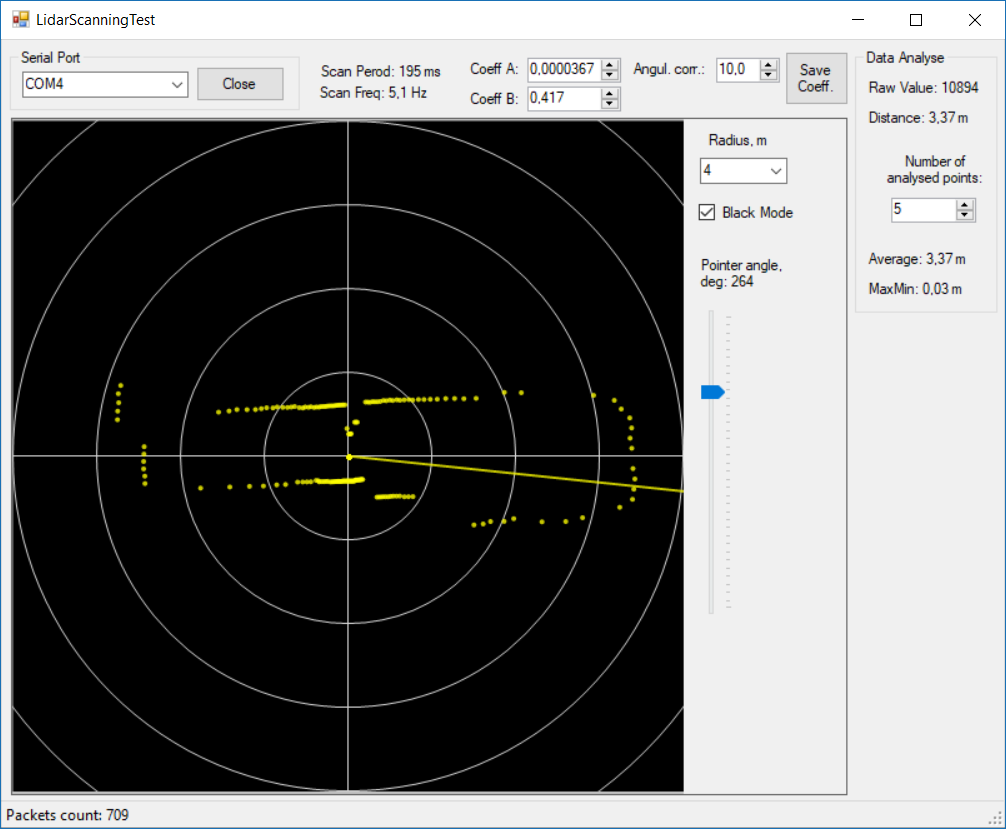
05/04/2019 at 13:36 • 0 commentsI have published PC utility for testing my Lidar: "LidarScanningTest". It is published with its source files at the Github.
Screenshot:
![]()
-
Autonomous robot moving with Open Simple Lidar
04/17/2018 at 19:21 • 0 commentsI write a special simple navigation node for the ROS called "simple_nav".
Here is a video of robot autonomous moving to the given goal point:
-
Interference filter
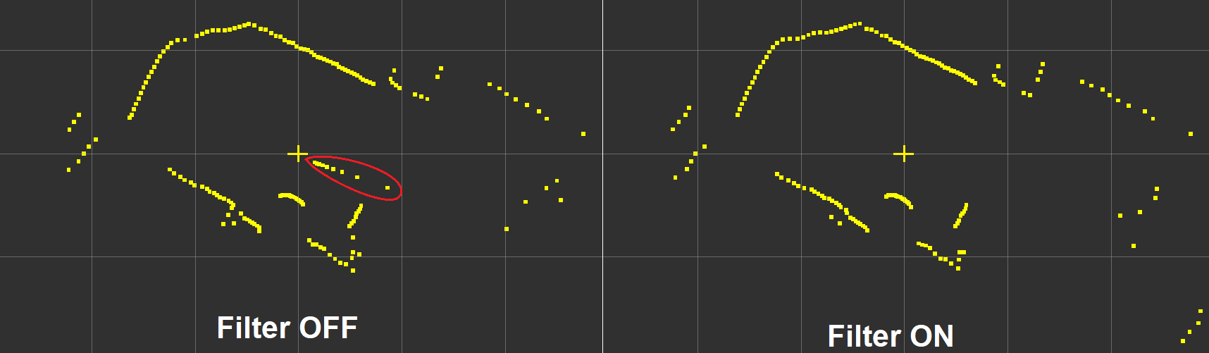
04/10/2018 at 18:45 • 0 commentsI'm using interference filter in my lidar: https://en.wikipedia.org/wiki/Interference_filter
It is used to decrease ambient light from different sources.
Here is example of filter working:
![]()
The left picture show influence of the lamp light (it is placed to the floor) to the Lidar image. Right picture was captured with filter installed.
-
Updated PCB
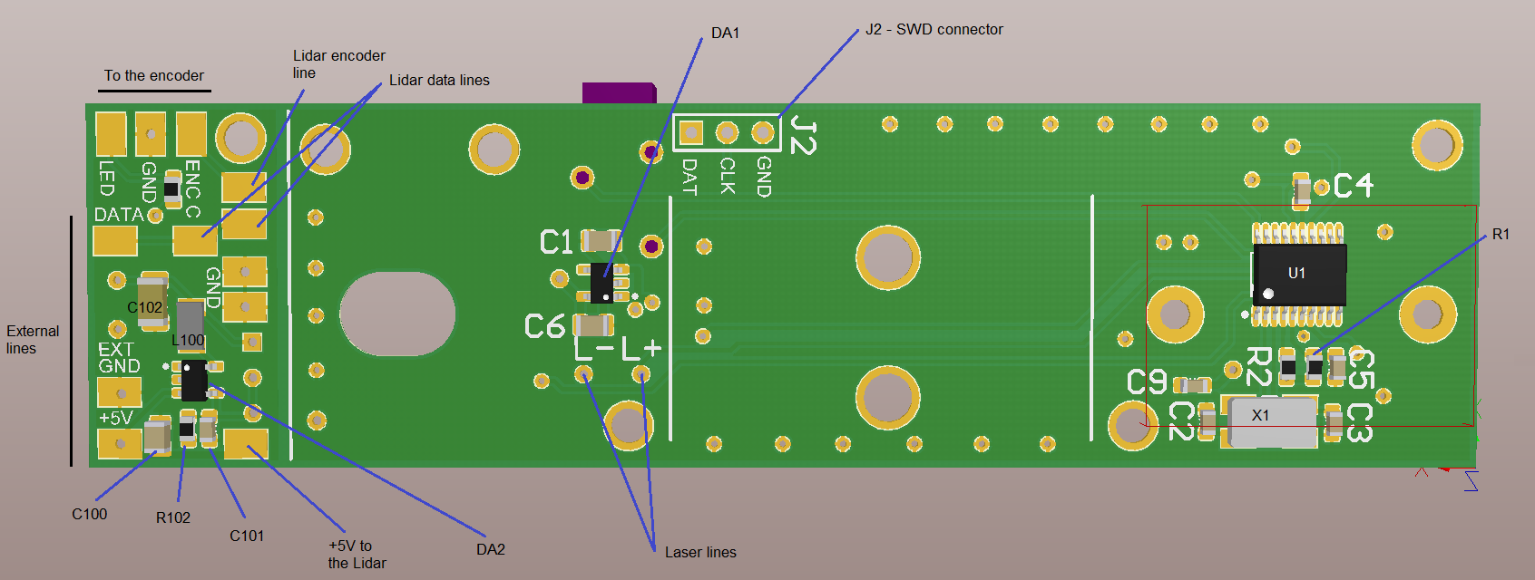
03/04/2018 at 16:42 • 0 commentsI have updated PCB of the Open Simple Lidar.
I have routed and placed small motor board together with the main PCB of the lidar. Earlier that motor PCB must be produced separately, but now only one common PCB in needed to be produced. Motor board must be cut from the main PCB before assembling the main PCB.
Also I draw some descriptions for assembling PCB.
New PCB image (motor PCB is on the left):
![]()
Updated files: https://github.com/iliasam/OpenSimpleLidar/tree/master/PCB
-
Testing Lidar with ROS
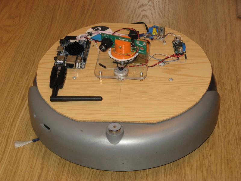
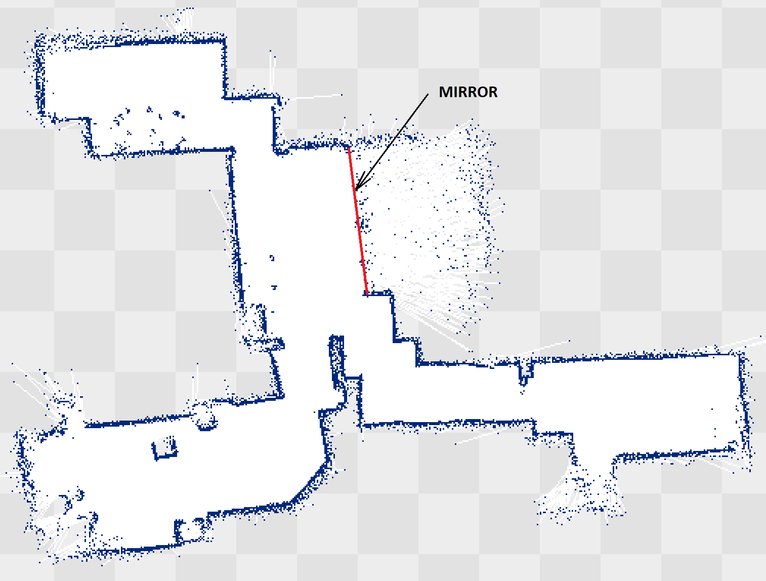
09/19/2017 at 18:44 • 0 commentsI had installed my Open Simple Lidar to the old Roomba and tested it with ROS (including Hector SLAM):
Photo of the lidar installed at the Roomba:
![]()
The left board is Orange Pi PC running ROS nodes (Lidar node, Roomba node, Hector SLAM).
All robot controlling was manual (using keyboard).The resulting map of the rooms:
This map was created with a lidar working in 2 deg angular resolution mode.
Also I had published Firmware code and lidar ROS node at the Github.
Next step is increasing parameters of the Lidar by optimizing its firmware.
-
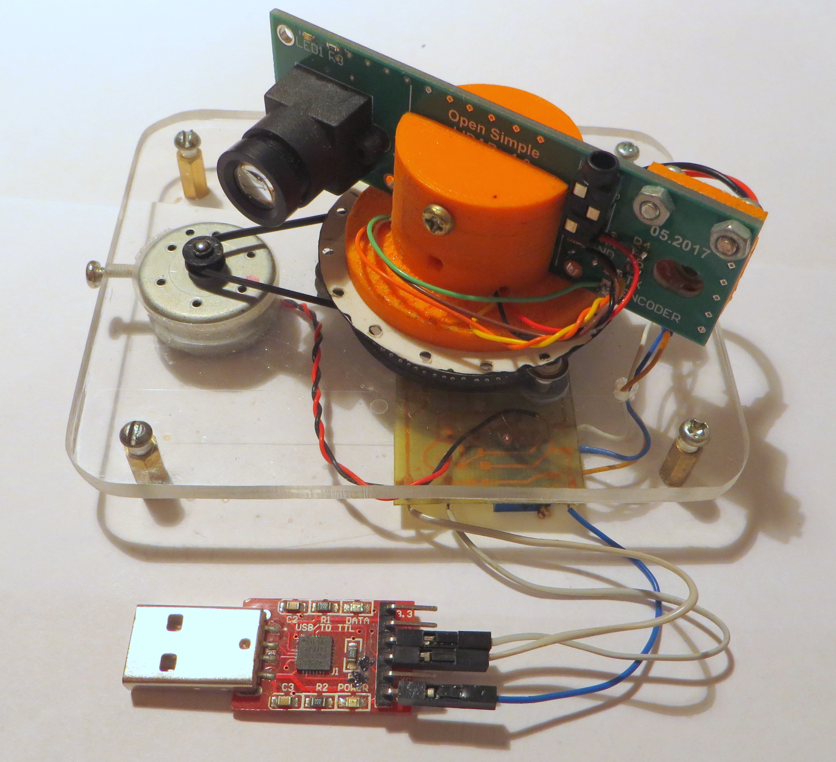
Open Simple LIDAR is fully assembled!
09/11/2017 at 19:14 • 0 commentsHere is the photo of the assembled LIDAR:
![]()
Last thing that I had installed is the small PCB with DC-DC converter for powering motor.
Photo of the installed board:![]()
This board also simplifies connections between LIDAR's components.
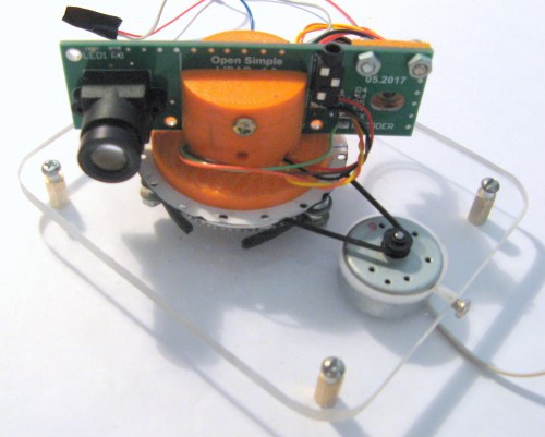
Photo with the scanning head installed:
![]()
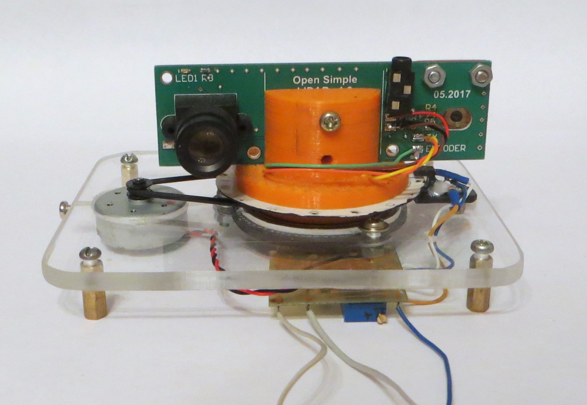
Front view of the assembled LIDAR:
![]()
My next step - write a node for ROS and to test SLAM algorithm.
-
First tests of my Lidar
08/31/2017 at 11:47 • 0 commentsI have done with basic firmware for my Lidar.
There were some problem with encoder signals - UART communication produce some electrical noise at the encoder's line.
Here is a video of first test:
I decrease angle resolution to 2 deg to increase rotational speed - it is near 5 rotations per second.
Circles at the "radar" images are 1, 2, 3 m in radius.
-
Testing encoder
08/14/2017 at 18:14 • 0 commentsI wrote a simple program for testing encoder. It's just blinking led at PCB when there is a hole in encoder disk.
Photo of LIDAR with big exposure:
![]()
-
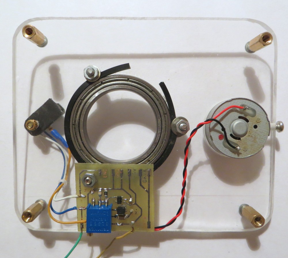
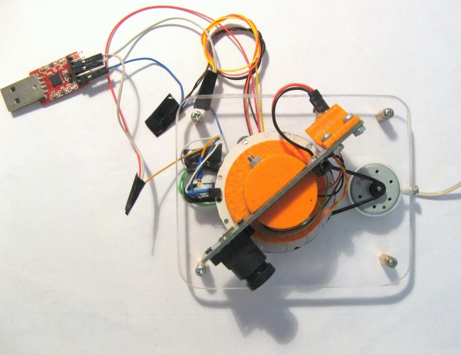
Assembling LIDAR
08/13/2017 at 15:46 • 0 commentsNow it is time to final LIDAR assembling.
I have installed encoder to the "main plate", installed the PCB to the PCB holder, installed slip ring to the PCB holder, solder wires of the slip ring to the PCB pads.
Photo of the assembled LIDAR:![]()
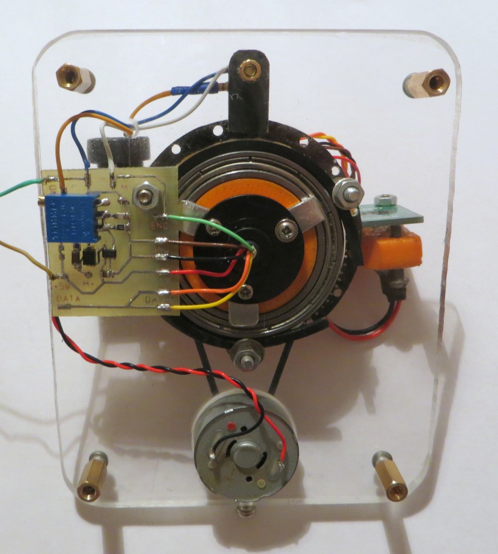
Side view:
![]()
I have tested mechanics of the LIDAR - everything is working fine, the eccentricity of the LIDAR rotating head is not very big.
Encoder is working fine too - oscilloscope shows a good signal.
Next steps are assembling small PCB for motor controlling and programming.