Close
0%
0%

Super Mario Odyssey Eyes

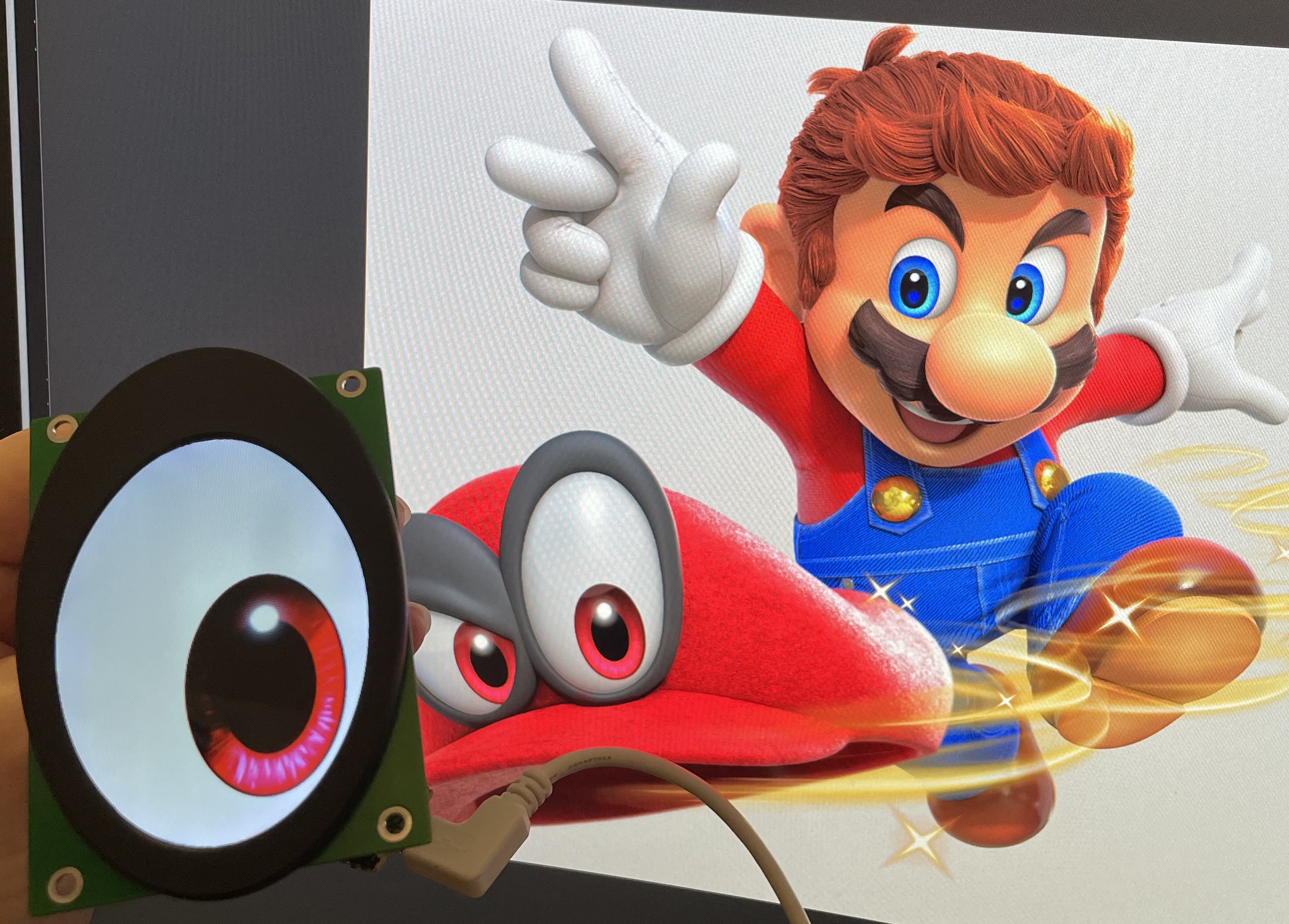
An oval screen driven by the rp2040 to create cartoon eyes like the character Cappy from Super Mario Odyssey

Similar projects worth following
One day, while browsing through Aliexpress, I saw some cool oval LCD screens. I saved them for later. Then my family started playing Super Mario Odyssey. Those oval screens would make perfect eyes for a costume! And a costume would be easy, it's just a hat!

The project originally started in March of 2025. I had datasheets from the Aliexpress seller but no source code, so I had no idea how to drive the LCD. But it worked with the included STM32-based dev board. After reading through the datasheet, I thought it should be possible to drive the LCD using the RP2040. So I hooked it up to a Raspberry Pi Pico and started writing firmware. That took a lot of effort to figure out. With the help of a forum post, I eventually got a red square to draw on the screen! I did most of the firmware work in March and designed a new PCB April of 2025 but then left it alone for a year.

In July 2026 I finally ordered PCB assembly to get it to a 90% completed status. It's good enough for now.

This project is an oval screen driven by an rp2040 on a custom board.

KiCad project files, source code, and 3D printable files will be incoming. I need to clean them up before I feel comfortable publishing them though.

The goal for this project was to make the Cappy character from Super Mario Odyssey but these special screens can be used for nearly any cartoon character. I made the custom PCB fit to the back of the screen itself. The only limitation is its shrouding.
super-mario-odyssey-eyes-kicad-project.zip

The KiCad files with schematic and board layout

Zip Archive - 234.68 kB - 08/01/2026 at 11:30

Download

  • Working with the screen

    Matthew • 08/01/2026 at 10:57 • 0 comments

    Without this forum post, I never would have gotten this far. Sincere thanks to Simbarashe Bryne Chipembe because their set of init commands really helped me figure things out. To understand why their init sequence mattered, let's take a look at the pinout for the display itsef. (I mostly copy/pasted this from the datasheet, so any English mistakes may have been carried over)

    Pin numberNameDescription
    1GND 
    2IOVCCI/O POWER 1.8V/2.8V(typ)
    3VCCPOWER 2.8V-3.0V
    4CSChip select signal. Amplitude: IOVCC-GND Low: the driver is selected and accessible High: the driver is not selected and not accessible. Tie to IOVCC when not in use
    5RSRegister select signal.Amplitude: IOVCC-GND Low: select Index register High: select control register. Tie to IOVCC when not in use
    6WRWrite strobe signal in 80-system bus interface operation and enables write operation when WRX is low. Synchronous clock signal (SCL) in serial interface operation. Amplitude: IOVCC-GND. Tie to IOVCC when not in use
    7RDRead strobe signal in 80-system bus interface operation and enables read operation when RDX is low. Amplitude: IOVCC-GND. Tie to IOVCC when not in use
    8DB016-bit parallel bi-directional data bus for 80-system interface operation (Amplitude: IOVCC-GND). 16-bit I/F: DB15-DB0 are used. 8-bit I/F: DB15-DB8 are used.
    9DB1"
    10DB2"
    11DB3"
    12DB4"
    13DB5"
    14DB6"
    15DB7"
    16DB8"
    17DB9"
    18DB10"
    19DB11"
    20DB12"
    21DB13"
    22DB14"
    23DB15"
    24RESETReset pad. Initializes the IC when it is low. Must be reset after power-on.
    25LCM_IDreserved (not sure what it's reserved for)
    26GND 
    27IM0Select a mode to interface to host processor. (Amplitude: IOVCC ~GND) IM0: LOW,80-system 16-bit interface IM0: HIGH,80-system 8-bit interface
    28NC/FMARKreserved
    29VCIPOWER 2.8V-3.0V
    30LEDK4LED Cathode
    31LEDK3LED Cathode
    32LEDK2LED Cathode
    33LEDK1 LED Cathode
    34LEDALED Anode
    35YU/NCNot connected but would be for the touch panel
    36XL/NCNot connected but would be for the touch panel
    37YD/NCNot connected but would be for the touch panel
    38XR/NCNot connected but would be for the touch panel

    The ILI9335 driver is a chip on the display's FPC connector that then breaks out to the individual pins in the LCD matrix. The pins above are just the ones exposed from the ILI9335 driver to the FPC connector and on to the dev board. To replicate the dev board, I needed to connect to these pins. 

    The dev board pulled IM0 low, so it was a 16-bit interface. I wired the pins up to the pico the same way the dev board was wired up. Though, the DB0-15 pins were wired in order so I could try using pio (more on that later).

    The 16-bit interface works like this when writing:

    1. Flip CS to low

    2. Flip RS to low (because we're writing to the index registers)

    3. Keep RD high

    4. Flip WR to low

    5. Set the bits for DB0-15. The first set of bits will be the index registers

    6. Set WR to high

    7. Set RS to high (Index registers are written, so this is now high)

    8. (short wait)

    9. Set WR to low

    10. Set the bits for DB0-15. This second set of bits are the data registers

    11. Set WR to high

    12. Set CS to high 

    Done.

    So how does this relate to the init code from that forum post? Well, every time they ran their `WRITE_LCD_REG` function, they specified the register and the data to write. I read through the datasheet multiple times but for some reason, reading those lines finally clicked for me.


    Let's take the first command, `WRITE_LCD_REG(0x01, 0x0100);`

    This would mean we do the following:

    1. Flip CS to low

    2. Flip RS to low

    3. Maintain RD as high

    4. Flip WR to low

    5. Set pins DB0-15 to be 0000 0000 0000 0001

    6. Set WR to high

    7. Set RS to high

    8. Wait 10ns or so

    9. Set WR to low

    10. Set the bits for the data, which is now: 0000 0001 0000 0000

    11. Set WR to high

    12. Set CS to high

    Then I just compared their data to the ILI9335 datasheet I got from the Aliexpress seller and was able to configure the display. When I wanted to write to certain sections...

    Read more »

View project log

Enjoy this project?

Share

Discussions

Similar Projects

Does this project spark your interest?

Become a member to follow this project and never miss any updates