Close
0%
0%

Galaga meets IoT

ESP8266 captures high scores as they occur on a Galaga PCB from the Golden Age of Arcade

Similar projects worth following
This project explores the possibility of using an ESP8266 to sniff High Scores from the Data Bus on the original Galaga PCB (and other Golden Era games) and send to a local Web Server for processing and displaying.

Fortunately I had access to an old but capable Logic Analyser and to my surprise finally managed to capture "00,00,00,00,02,24" during the startup sequence. I was on to something. I had found the memory chips that store the High Score.

Wrongly thinking it would be trivial to use a micro like a ATmega328P I began experimenting with monitoring the address bus and sniffing the data bus for High Scores. Assumed that a modern micro would run rings around the likes of a Z80 operating at 3.072 MHz. I was wrong.

Discovered the Bus is very busy (6 High Score bytes are written within 44us) and became clear that a hardware solution was needed.

Luckily I happened across a small collection of GAL16V8A (Generic Array Logic) and began experimenting with these dev

GalagaIoT

Creating a web based IoT Galaga high scores capture seemed like a worthwhile project.

There are some good solutions that already exist that include JROKs fine Galaga Enhancement pack but it is bordering on unobtanium (for me in Aus) and does not meet all my requirements.

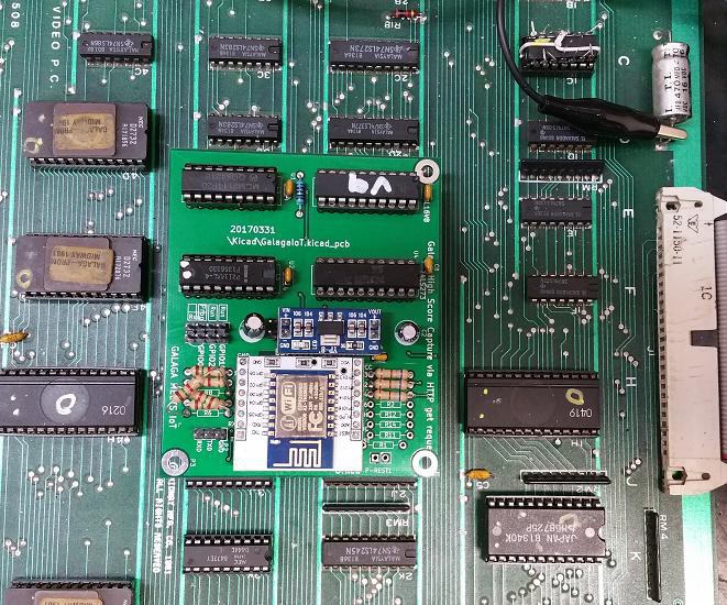
Behold GalagaIoT.


Requirements:

Record System Up (powered on times)

Time Stamp High Scores

Record Any Highest Score since last power on

Store virtually an unlimited number of High Scores

No ROM code modifications

Low(ish) Cost $20 AUD ($8 GAL, $2 74ls273, $4 ESP8266, $3 PCB, $1 3.3v reg, $2 caps and resistors etc)


Bonuses:

Learn about GALs

Experiment with Kicad

Learn about Galaga, one of my all time favourites

Could be expanded to log play time statics,, such as individual game play times, total game play times.

Maybe possible (with significant modification) to repopulate the High Score table with the 5 highest scores at power on.


Fails:

Does not repopulate the high score table at reset or power on.

Does not increase the number of digits in the high score from 6 to 7 (as I believe the enhancement pack does.)

Only records High Scores that appear at the very top of the High Score Table. If a player makes it into the high score Top 5 but is not the highest then the score is not recorded. (Future enhancement perhaps)


How it Works: Summary

Basically Galaga address bus is constantly monitored for write accesses that relate to high score updates. Whenever there is an address hit, the data on the data bus is latched and stored in an array.

The array is constantly scanned for tell tale signs that a high score update has occurred (as distinct from random writes that occur during Galaga's startup sequence)

The high score and the players initials are then sent to a web server for further processing, storing and displaying.


How it Works: Details

Whenever there is a new *top* high score (just getting into the high score table does not count unless it is the top score) Galaga will copy it from screen memory at location 83ED - 83F2 to ram location 8A20 - 8A25 (6 digits on reset RAM will contain " 20000" but stored as 00 00 00 00 02 24)

It then initialises the initials stored at 8A3E - 8A41 (3 chars) to "AAA" and waits about 30 secs for the player to enter their initials.

If the player enters their initials, then these are copied to 8A3E - 8A41 if nothing is entered Galaga again writes "AAA" to RAM locations 8A3E - 8A41 .

GalagaIoT constantly monitors the address bus (Buffer Address Bus "A") and records in an array (score[]) any writes to the high score and initials memory locations 8A20 - 8A25 and 8A3E - 8A41 respectively.

GalagaIoT also converts Galaga character code (I call GALASCII) to ASCII. GALASCII codes of interest are 0x00 - 0x09 -> 0 - 9, 0x0A - 0x23 -> A - Z, 0x2A -> "." and 0x24 -> " ".

It also continual scans the array for a match of "AAA" which signifies a new high score has just been achieved and the system is waiting for initials to be input.

GalagaIoT then waits 30 secs (for the initials entry sequence to finish) and then assumes that the last 12 characters in the array will contain the high score. (Yes, its a cludge). These characters (eg "36250AAASAM") are sent to the webserver where they are further processed (see galagaHS.pl). Processing includes replacing AAA with " " , "b" with " " and "c" with "." It then appends the score/initials combination (eg "36250,SAM") to the high score file.

The high score file is then included as part Galaga.htm whenever a browser points to it.

A GAL16V8 (Generic Array Logic) is used to monitor the address bus for any address hits. It monitors the physical bus (Buffer Address Bus "A") at RAM 2114 location 3E on the Galaga Video PCB. There is only 10 address lines (A9 - A0) so the GAL is only matching a address hits in the range of 0x220 -> 0x225 and not 8A20 -> 8A25). For the hit to be valid the write enable (WE) and chip select (CS) pins must be also active. See galaga.pds for the GAL program/config file.

The GAL asserts a negative going clock (output...

Read more »

IoTGalaga_V13.ino

Hopefully the final version

ino - 15.86 kB - 01/18/2018 at 01:52

Download

GALAGA.JED

This is the fuse file that was generated by PALASM. This file was burned using a Micromaster 1000+ using ICE Technology: WINLV software on to the GAL16V8A

jed - 3.13 kB - 01/12/2018 at 11:49

Download

IoTGalaga_V12_flipped_5_0.ino

This is still a messy version but works with the assembled PCB with the bodged GPIO0 and GPIO5 swap

ino - 15.76 kB - 01/11/2018 at 12:21

Download

IoTGalaga_V9.ino

A working (very rough) version of the ESP8266 code. Needs to be tidied and commented

ino - 5.41 kB - 12/03/2016 at 11:03

Download

GalagaIoT.sch

Schematic capture. We (KiCad and I) struggled with the fact that this is a daughter board and many of the input are actually driven from the motherboard. DRC would report that inputs are connected to each other and not driven.

sch - 15.38 kB - 12/03/2016 at 10:36

Download

View all 11 files

  • 1 × GAL16V8A Logic ICs / Programmable Logic: PLDs
  • 1 × 74LS273 Electronic Components / Misc. Electronic Components
  • 1 × ESP8266
  • 1 × Original Galaga PCB

  • PCB's manufactured, populated and its works!!!

    justin.richards01/11/2018 at 12:04 0 comments

    Over a year later and finally got around to dusting off the PCB's, populating with components and began testing.  

    Surprisingly, initial tests looked promising, but eventually hit a snag with GPIO0 pulled low at powerup which results in the ESP8266 booting into flash/program mode when the Galaga board was powered on.

    Luckily a simple bodge swapping GPIO5 and GPIO0 with the relevant code changes resulted in a functional high score sniffer. 

    So basically, this project is completed!!! I can finally move on.

    Next stage, tidy the code, install into a cabinet and see how it behaves in the wild.

    Above GalagaIoT installed on the Video PCB.  The bodge can be seen where GPIO0 and GPIO5 resistors were swapped.

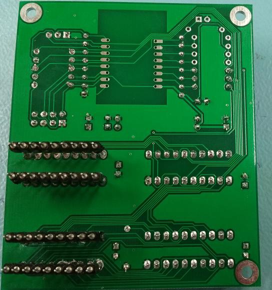
    These extended pins were needed to facilitate plugging into RAM sockets 3E and 3F.  A little fiddly and time consuming. 

  • Volatile was the key

    justin.richards11/30/2016 at 16:59 0 comments

    As per discussion suggestion, declared the array used by the interrupt routine as type *Volatile* .

    The ESP8266 now behaves for the most. Just need to do some tidying up, make some boards etc. Will give them a bit of a polish and upload.

    Have just uploaded rough schematic.

    So in summary, the GAL16V8 triggers on matched addresses, which triggers the 273 to latch the data and also generate a interrupt to read the latched data.

    The esp constantly scan writes to the bus for three consectutive spaces " . In GALASSCI this is char 0x24. Once it has a hit it waites a further 30 secs in anticipation that the high score initials are getting entered. It then processes the GALASSCI chars, converts to ascii and sends to web server for minor additional processing and displaying the time stamped high scores.

  • ESP8266 Issues Responding to interrupts

    justin.richards11/13/2016 at 05:01 5 comments

    I have been so close to a working solution but always come back to issues with ESP8266 latency delay when responding to the first interrupt.

    Interrupt service becomes when of an issue it seems when examining any of the variables that modified during the interrupt routine.

    I incorrectly arrived at a conclusion that the ESP8266 is fast enough to respond to each new write to the 2114 in a timely manner. It kind of is but if your main loop is referring to any of the variable set in the INT then it is no longer reliable.

    Have decided to go back to the original idea of once the INT is triggered, read and record the state of the IO as fast as possible then post process the changes by looking for the toggle bit . It uses 1 extra pin but I think it is the only way.

    So it is back to the drawing board.

  • EQUATIONS Compile issues solved

    justin.richards11/07/2016 at 01:50 0 comments

    Solved the previous compile i8ssue with

    Z := /Z

    which toggles Z on every rising pulse on the Clock (Pin 1)

    Z output is then used to differentiate between subsequent hi score digit writes.

    This now fixes the issue where a high score with repeat digits such as 30556 would be interpreted as 3056.

    Need to tidy the ESP8266 code and think about a final PCB board layout.

  • High scores are getting sent to server

    justin.richards11/04/2016 at 10:29 1 comment

    Hi scores are getting sent to webserver but as this is a cludge it is not yet bullet proof.

    Seeking help to write flip flop equation for GAL.

    So far I have this for the address matches

    /X = /WE * /CS * J*/I*/H*/G*F*/E*/D*C*/B*A + ;Addr 225 [8A25]

    /WE * /CS * J*/I*/H*/G*F*/E*/D*C*/B*/A +;Addr 224 [8A24]

    /WE * /CS * J*/I*/H*/G*F*/E*/D*/C*B*A +;Addr 223 [8A23]

    /WE * /CS * J*/I*/H*/G*F*/E*/D*/C*B*/A +;Addr 222 [8A22]

    /WE * /CS * J*/I*/H*/G*F*/E*/D*/C*/B*A +;Addr 221 [8A21]

    /WE * /CS * J*/I*/H*/G*F*/E*/D*/C*/B*/A ;Addr 220 [8A20]

    y = /X;

    which works well but the following fails to compile.

    Z = /Z;

    Z.clkf = X;

    Hoping someone may be familiar and set me straight.

View all 5 project logs

Enjoy this project?

Share

Discussions

justin.richards wrote 11/07/2016 at 02:46 point

Hi Hacker404, 

Thanks for the input.

you are correct. The GALs were lying around and they presented a mystery.  It so happens that I had access to a handful of these and a burner .  So pondered what would make an ideal for them.  The Galaga machine is getting popular and competition was on the increase so I thought a high score logger would be the go.  There are solutions out there but where is the fun in that.

They are less of a mystery now and was very pleased after coding, compiling and recently burning one to discover that the logic behaved as expected.

I am not sure what the language is called but I use PALASM (in DOSBOX) to compile the PDS files.

The circuit is relatively straight forward.  Basically the 10  address pins plus WE and CS  of the 2114 are wired to 12  pins configured as inputs on the GAL. 

The 8 data lines are connected to the 74LS273 D0 -D7.

The 273 latches when ever there is an address match.

The ESP8266 then reads the 273 Q0-Q3  outputs (as fast as it can)

I hope to put together a schematic soonish.

Thanks for your kind offers and will keep them in mind.

I do like your suggestion of a single chip solution.

Australia, which state?I am Perth based. And who do you write VHDL for?  (FPGA's are another mystery. One day...)

  Are you sure? yes | no

Hacker404 wrote 11/07/2016 at 01:20 point

It's a bit of a kludge to use a CPLD along with a 74xxx chip. I guess you had them lying around?

There are still 5Volt CPLD's around that are cheap and everything will fit into the CPLD with no other external logic needed. An example would be Xilinx XC9536 that has 36 registers so it would be fine to capture the 20 bits that you need. A larger XC9572 has 72 registers. 

Then there are 5Volt 'tolerant' chips like Xilinx XC9536XL (36 regs) XC9572XL (72 regs), Altera EPM240 (approx 180 regs) EPM570 (approx 450 regs). 

The Xilinx series mentioned above use exactly the same macro cell as the 16v8 and 22v11 so there what your used to but much larger. All the above chips can be re-written so they are NOT OTP chips like the GALs/PALs. 

The 16v8 only has 8 registers and you may be able to squeeze one or two more into combinational logic but I doubt that would fit in with the address decoding. 

I write VHDL which is sort of like what you have above. I have seen the code that your using before but I don't remember what it's called. Is it CUPL? If you post some links so that I can quickly learn it then (with the schematic) I can convert the whole circuit into that language and tell you size chip it will fit. I can also give the equivalent VHDL for the chips I mentioned. 

Also most of the chips I mentioned above are QFP. The smaller Xilinx chips may still around in DIP. But by the most part this is what you will find - 

XC9536(XL) XC9537(XL) QFP32 0.8mm pitch easy to hand solder

EPM240 EPM570 QFP100 0.5mm pitch harder to hand solder

The 5Volt 'tolerant' chips don't have much of a noise margin with TTL logic so run them at 3.6Volts instead of 3.3Volts - manufacture approved by Xilinx. 

There are plenty of QFP32 to DIP adapters or QFP100 to square 0.1" adapters around. 

I also have about 100 XC9536XL chips here and I can program some and send them to you and even put them on a DIP adapter if you want. I am Australia. Just remember to run them at 3.6Volts. or I could even make a custom boars with regulator included.

  Are you sure? yes | no

Hacker404 wrote 11/07/2016 at 07:13 point

Damn lol, I just learnt CUPL and PALASM is completely different and there are conflicting documents to describe the language. 

One says this for registered - 

PIN ? Q[0..3] REGISTERED ;

and := for registered 

and *= for latched but not sure what the difference is. The latch controls are .fset .freset and the register is .fclk .fen

I will get back to it later. What version of software are you using (any links)? I have about 20 of 22v11 here and some MACK PRO II chips as well it might do them for me. What burner are you using. 

I am in Cairns QLD. BBL

  Are you sure? yes | no

Similar Projects

Does this project spark your interest?

Become a member to follow this project and never miss any updates