justin.richards
-
PCB's manufactured, populated and its works!!!
01/11/2018 at 12:04 • 0 commentsOver a year later and finally got around to dusting off the PCB's, populating with components and began testing.
Surprisingly, initial tests looked promising, but eventually hit a snag with GPIO0 pulled low at powerup which results in the ESP8266 booting into flash/program mode when the Galaga board was powered on.
Luckily a simple bodge swapping GPIO5 and GPIO0 with the relevant code changes resulted in a functional high score sniffer.
So basically, this project is completed!!! I can finally move on.
Next stage, tidy the code, install into a cabinet and see how it behaves in the wild.
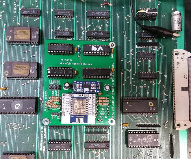
![]()
Above GalagaIoT installed on the Video PCB. The bodge can be seen where GPIO0 and GPIO5 resistors were swapped.
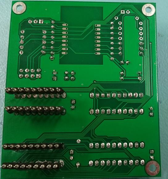
![]()
These extended pins were needed to facilitate plugging into RAM sockets 3E and 3F. A little fiddly and time consuming.
-
Volatile was the key
11/30/2016 at 16:59 • 0 commentsAs per discussion suggestion, declared the array used by the interrupt routine as type *Volatile* .
The ESP8266 now behaves for the most. Just need to do some tidying up, make some boards etc. Will give them a bit of a polish and upload.
Have just uploaded rough schematic.
So in summary, the GAL16V8 triggers on matched addresses, which triggers the 273 to latch the data and also generate a interrupt to read the latched data.
The esp constantly scan writes to the bus for three consectutive spaces " . In GALASSCI this is char 0x24. Once it has a hit it waites a further 30 secs in anticipation that the high score initials are getting entered. It then processes the GALASSCI chars, converts to ascii and sends to web server for minor additional processing and displaying the time stamped high scores.
-
ESP8266 Issues Responding to interrupts
11/13/2016 at 05:01 • 5 commentsI have been so close to a working solution but always come back to issues with ESP8266 latency delay when responding to the first interrupt.
Interrupt service becomes when of an issue it seems when examining any of the variables that modified during the interrupt routine.
I incorrectly arrived at a conclusion that the ESP8266 is fast enough to respond to each new write to the 2114 in a timely manner. It kind of is but if your main loop is referring to any of the variable set in the INT then it is no longer reliable.
Have decided to go back to the original idea of once the INT is triggered, read and record the state of the IO as fast as possible then post process the changes by looking for the toggle bit . It uses 1 extra pin but I think it is the only way.
So it is back to the drawing board.
-
EQUATIONS Compile issues solved
11/07/2016 at 01:50 • 0 commentsSolved the previous compile i8ssue with
Z := /Z
which toggles Z on every rising pulse on the Clock (Pin 1)
Z output is then used to differentiate between subsequent hi score digit writes.
This now fixes the issue where a high score with repeat digits such as 30556 would be interpreted as 3056.
Need to tidy the ESP8266 code and think about a final PCB board layout.
-
High scores are getting sent to server
11/04/2016 at 10:29 • 1 commentHi scores are getting sent to webserver but as this is a cludge it is not yet bullet proof.
Seeking help to write flip flop equation for GAL.
So far I have this for the address matches
/X = /WE * /CS * J*/I*/H*/G*F*/E*/D*C*/B*A + ;Addr 225 [8A25]
/WE * /CS * J*/I*/H*/G*F*/E*/D*C*/B*/A +;Addr 224 [8A24]
/WE * /CS * J*/I*/H*/G*F*/E*/D*/C*B*A +;Addr 223 [8A23]
/WE * /CS * J*/I*/H*/G*F*/E*/D*/C*B*/A +;Addr 222 [8A22]
/WE * /CS * J*/I*/H*/G*F*/E*/D*/C*/B*A +;Addr 221 [8A21]
/WE * /CS * J*/I*/H*/G*F*/E*/D*/C*/B*/A ;Addr 220 [8A20]
y = /X;
which works well but the following fails to compile.
Z = /Z;
Z.clkf = X;
Hoping someone may be familiar and set me straight.
Galaga meets IoT
ESP8266 captures high scores as they occur on a Galaga PCB from the Golden Age of Arcade