 skelly
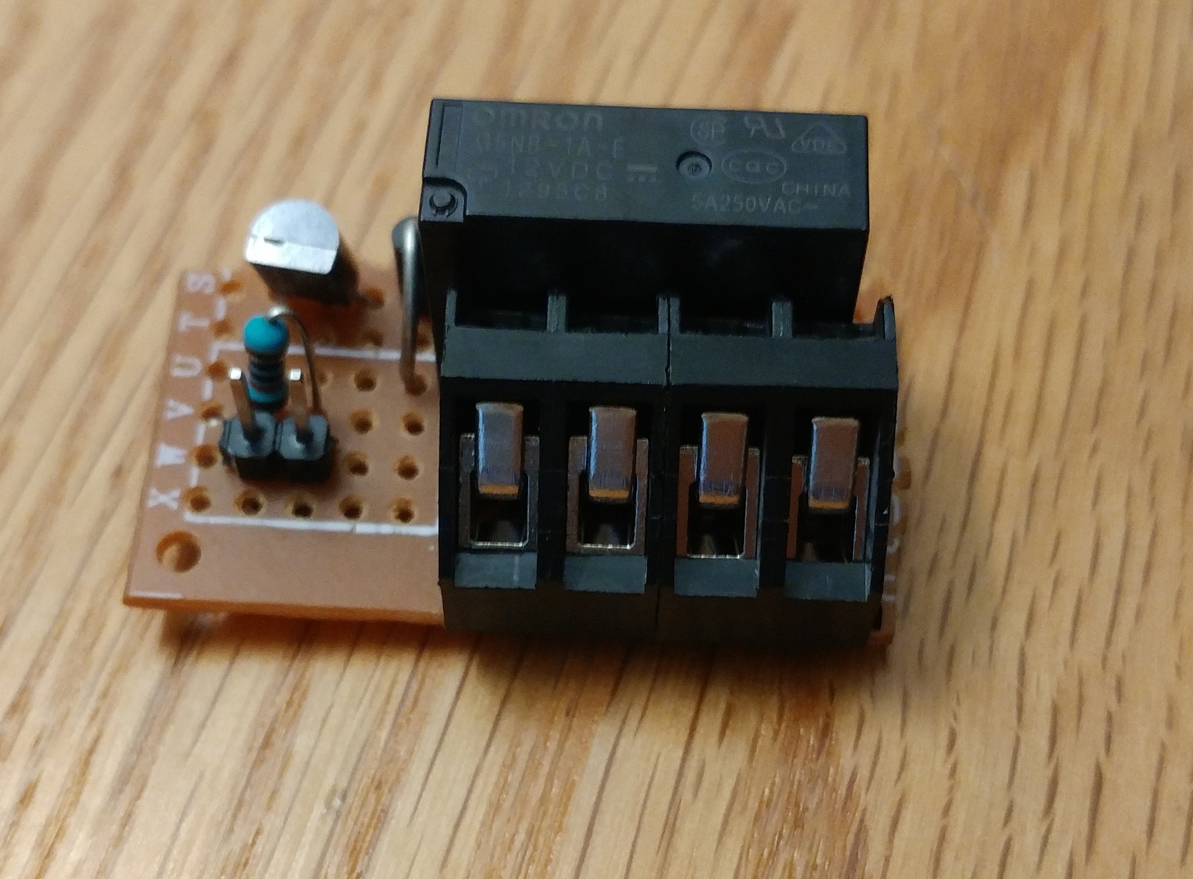
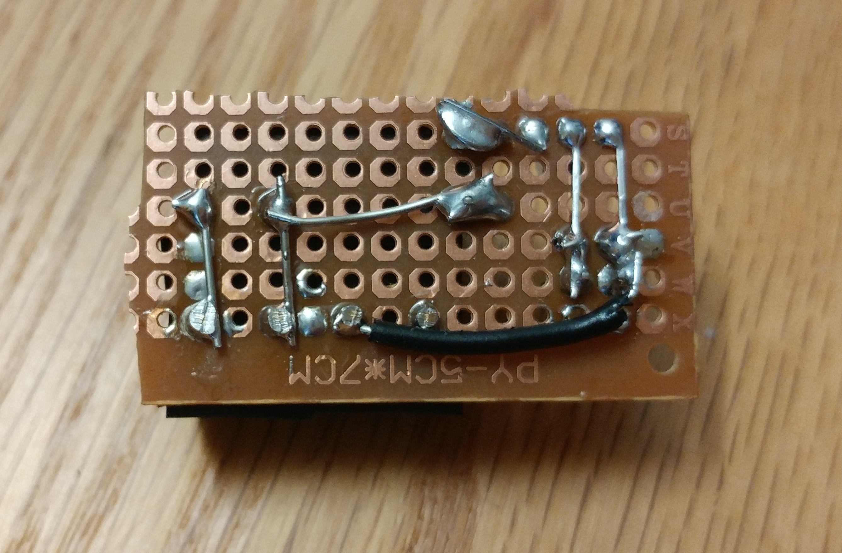
Now that I've verified that the circuit works on a breadboard, I assembled it on a more permanent protoboard. The soldering isn't the dick, but they're solid joints and it works as intended. I made a mistake when planning and purchasing parts and didn't think about the fact that the board will need to connect to both the Raspberry Pi's GPIO ground as well as the ground from the printer's power supply. This means I would have needed a 3-pin terminal block instead of a 2-pin. I just used 2x2-pin terminal blocks and left one pin unconnected.
Discussions
Become a Hackaday.io Member
Create an account to leave a comment. Already have an account? Log In.