Close
0%
0%

Giving a Honeywell HPA300 Air Purifier a New Brain

An open-source ESP32-S2 replacement controller for the Honeywell HPA300, with local controls, Wi-Fi, OTA, and Home Assistant.

Similar projects worth following
0 followers
I built a replacement controller for the Honeywell HPA300 air purifier. Designed around an ESP32-S2, it preserves the original touch controls and four fan speeds while adding Wi-Fi, OTA updates, and Home Assistant integration with HACS.

The project includes a mechanically compatible custom PCB, hardware-enforced fan-speed interlocking, ESP-IDF firmware, and a local-first design that keeps the purifier fully functional even when the network is down. Hardware, firmware, BOM, and manufacturing files are all open source.

Background

I had been running a Honeywell HEPA filter (HPA300 series) for years, partly as white noise, and partly in preparation for wildfire season and the famously leaky windows in my 1950s California apartment. Not being particularly good at leaving well enough alone I wondered whether the purifier could respond to what was actually happening in the room instead of running at a fixed speed all day.

And thus became the project: keep the purifier completely usable as a normal appliance, but add a wireless control layer. And of course as an excuse to learn ESP32, make a custom PCB, and experimented with AI in embedded programming. This later became closed loop control with Home Assistant in the middle, and an AirGradient monitor to provide a source of PM2.5 particle counting

Reverse Engineering the Original Controller

The first challenge is identifying that to remove the front housing requires a 6-inch-long security T20 driver.

Once inside, the electrical architecture is essentially four pieces:

  • a multi-tapped AC fan motor
  • a run capacitor
  • an AC power/control board
  • a low-voltage front-panel control board

The fan motor exposes separate taps for its four speed settings. Each speed is switched by its own triac on the AC control board, with each triac controlled through an optocoupler. The low-voltage front-panel board drives those optocouplers directly.

The AC board also supplies power to the front panel. It rectifies the incoming AC, steps it down through a switching/flyback supply, and ultimately provides a regulated 5V rail to the controller. 

This architecture suggested a clean boundary for the project. Instead of modifying the mains-side board or replacing the motor-control circuitry, I could leave the entire AC section untouched and replace only the low-voltage front-panel controller. That made the modification comparatively clean and reversible while preserving the parts of the purifier already designed to handle mains voltage and the fan motor.

The goal became to reproduce the original front panel as faithfully as possible for local operation, then add Wi-Fi as an additional control layer rather than making the appliance dependent on it.

The replacement controller therefore needed to reproduce all of the original local functions:

  1. Six capacitive-touch inputs
  2. Eight status LEDs
  3. Four fan-speed selections
  4. Timed shutoff
  5. LED dimming
  6. Filter-life reminders

  • Making Bad Fan States Impossible

    patmont3 hours ago 0 comments

    One failure mode stood out very early in the design: energizing more than one motor-speed tap at the same time.

    The HPA300 uses a multi-tapped AC fan motor. Under normal operation, the controller selects exactly one of four taps, corresponding to the four fan speeds. With one speed selected, line voltage is applied to one tap and the motor operates as intended.

    The ugly case is what happens if two taps are energized at once. Driving two simultaneously can create unintended current paths through the tapped winding and potentially subject part of it, the triacs, or both to currents they were never intended to handle.

    Don't Trust Four GPIOs

    The obvious implementation would be four ESP32 GPIOs:

    GPIO 1 ─── Fan 1
    GPIO 2 ─── Fan 2
    GPIO 3 ─── Fan 3
    GPIO 4 ─── Fan 4

    That works right up until the firmware sets two of them high.

    There are plenty of ways software could accidentally ask for that condition. Bad GPIO logic. A race condition. A corrupted state. An unexpected boot configuration. Or, perhaps most realistically in my case, amateur programming. All were present in today's forecast.

    Software can promise not to do that; I wanted guarantees.

    So I made this a hardware requirement:

    The replacement controller must make it electrically impossible to assert more than one of the four 5 V fan-select outputs at a time.

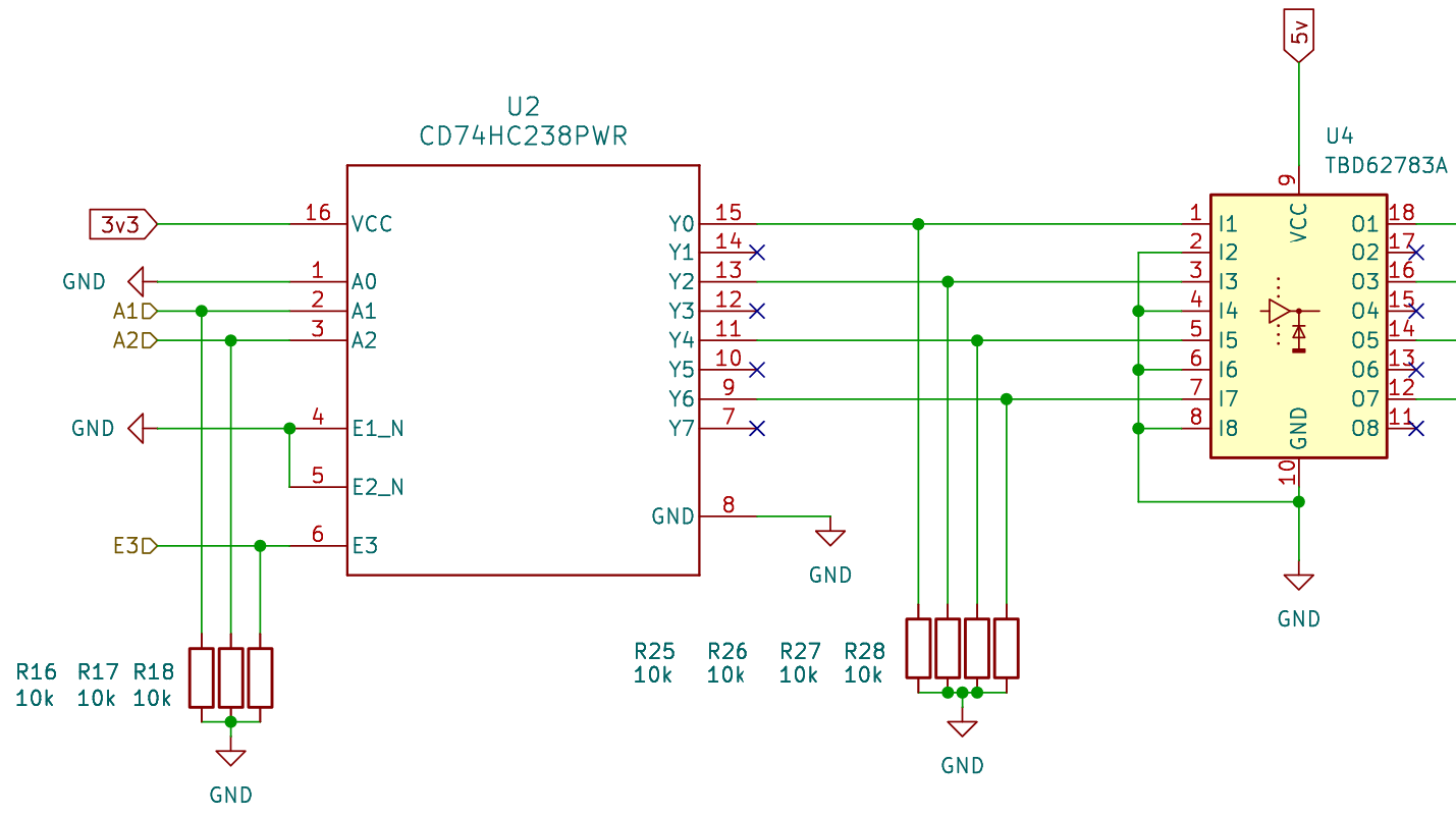
    This is where the 3-to-8 decoder comes in.

    Edit

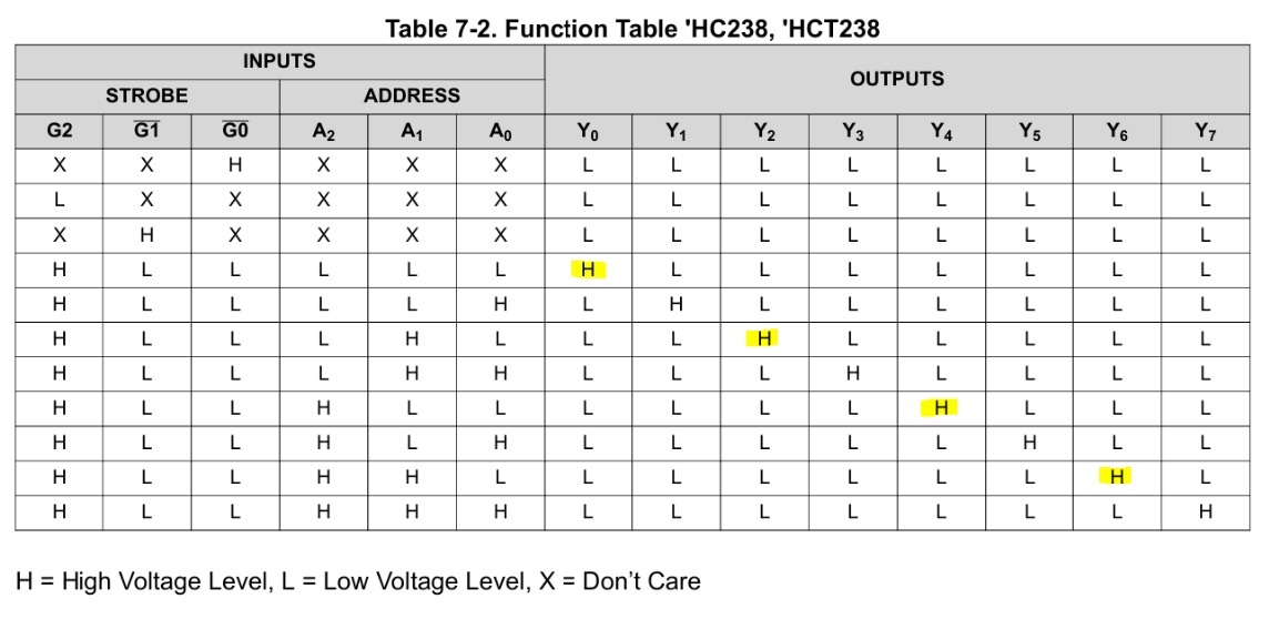
    A decoder accepts a binary address and asserts exactly one output corresponding to that address. No combination of address inputs can command two outputs simultaneously. A 2-to-4 decoder would have been enough, but 3-to-8 parts were much easier to source. The extra outputs also gave me an opportunity to make the physical implementation a little more fault tolerant.

    I use Y0, Y2, Y4, and Y6 for the four fan commands and leave every odd output between them unconnected.

    That means adjacent active outputs are separated by an unused decoder output, adding some physical separation between fan-control nets on the PCB. A solder bridge or contamination across adjacent decoder pins is therefore less likely to directly connect two valid fan commands.

    Because only four addresses are required, the least-significant address input, A0, is permanently tied low. The two active-low enable inputs are also permanently asserted, leaving the decoder's active-high enable as the master on/off control.

    So there are 3 signals left to control: A1, A2, and E2

    Edit

    The input states were chosen so that the two crudest GPIO failure modes both fail safely.

    • Everything Low (ESP32 is unpowered, reset, not configured)
      • The decoder's enable input is therefore held inactive and all fan outputs remain off.
    • Everything High (bad GPIO behavior, bad configuration)
      • Rather than allowing that state to correspond to a valid fan speed, the decoder is arranged so that the all-high address selects Y7, which is unused.

    Between those extremes, the decoder still provides the fundamental guarantee: only one output can ever be asserted at a time. Software is allowed to choose the wrong fan speed. It is not allowed to create an electrically invalid combination.

View project log

Enjoy this project?

Share

Discussions

Does this project spark your interest?

Become a member to follow this project and never miss any updates