 patmont
One failure mode stood out very early in the design: energizing more than one motor-speed tap at the same time.
The HPA300 uses a multi-tapped AC fan motor. Under normal operation, the controller selects exactly one of four taps, corresponding to the four fan speeds. With one speed selected, line voltage is applied to one tap and the motor operates as intended.
The ugly case is what happens if two taps are energized at once. Driving two simultaneously can create unintended current paths through the tapped winding and potentially subject part of it, the triacs, or both to currents they were never intended to handle.
Don't Trust Four GPIOs
The obvious implementation would be four ESP32 GPIOs:
GPIO 1 ─── Fan 1
GPIO 2 ─── Fan 2
GPIO 3 ─── Fan 3
GPIO 4 ─── Fan 4
That works right up until the firmware sets two of them high.
There are plenty of ways software could accidentally ask for that condition. Bad GPIO logic. A race condition. A corrupted state. An unexpected boot configuration. Or, perhaps most realistically in my case, amateur programming. All were present in today's forecast.
Software can promise not to do that; I wanted guarantees.
So I made this a hardware requirement:
The replacement controller must make it electrically impossible to assert more than one of the four 5 V fan-select outputs at a time.
This is where the 3-to-8 decoder comes in.
Edit
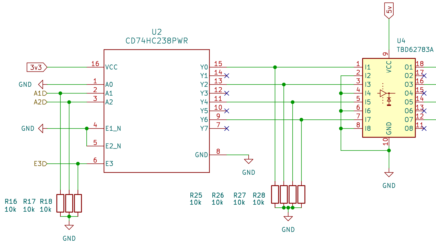
A decoder accepts a binary address and asserts exactly one output corresponding to that address. No combination of address inputs can command two outputs simultaneously. A 2-to-4 decoder would have been enough, but 3-to-8 parts were much easier to source. The extra outputs also gave me an opportunity to make the physical implementation a little more fault tolerant.
I use Y0, Y2, Y4, and Y6 for the four fan commands and leave every odd output between them unconnected.
That means adjacent active outputs are separated by an unused decoder output, adding some physical separation between fan-control nets on the PCB. A solder bridge or contamination across adjacent decoder pins is therefore less likely to directly connect two valid fan commands.
Because only four addresses are required, the least-significant address input, A0, is permanently tied low. The two active-low enable inputs are also permanently asserted, leaving the decoder's active-high enable as the master on/off control.
So there are 3 signals left to control: A1, A2, and E2
Edit
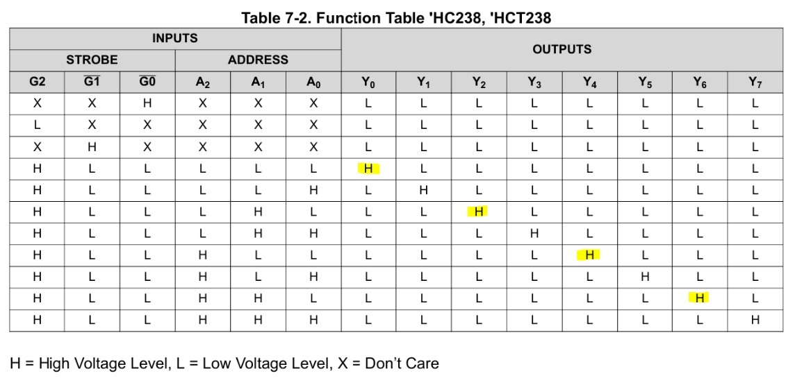
The input states were chosen so that the two crudest GPIO failure modes both fail safely.
- Everything Low (ESP32 is unpowered, reset, not configured)
- The decoder's enable input is therefore held inactive and all fan outputs remain off.
- Everything High (bad GPIO behavior, bad configuration)
- Rather than allowing that state to correspond to a valid fan speed, the decoder is arranged so that the all-high address selects Y7, which is unused.
Between those extremes, the decoder still provides the fundamental guarantee: only one output can ever be asserted at a time. Software is allowed to choose the wrong fan speed. It is not allowed to create an electrically invalid combination.
Discussions
Become a Hackaday.io Member
Create an account to leave a comment. Already have an account? Log In.