Close
0%
0%

PotWatch — the timer that waits for the boil

A clip-on kitchen timer that starts its countdown when the water hits a temperature you chose, not when you press a button.

Similar projects worth following
0 followers
A clip-on kitchen timer built on an ESP32-C3, a DS18B20 in a grounded stainless thermowell, and a BMP280 that corrects the boiling point for local air pressure. It waits until the water reaches the temperature you set, then runs the countdown and alarms. About €25 of common parts. Everything open: STL and STEP, GPLv3 firmware, schematic.

Every kitchen timer has the same flaw, and once you notice it you cannot un-notice it: it starts counting when you press the button.

But "three minutes for a soft-boiled egg" does not mean three minutes from when you pressed start. It means three minutes of boiling. So you stand at the stove watching for bubbles, press the button at some moment that feels about right, and accept that breakfast is a coin flip. A watched pot, as the saying goes, never boils.

PotWatch is a small device that clips onto the rim of the pot, drops a stainless probe into the water, and takes that judgement away from you. It waits until the water reaches the temperature it is looking for, and only then starts the countdown. Then it shouts.

That is the whole idea. The interesting part is what "the temperature it is looking for" turned out to mean.

Water does not boil at 100 °C

This is the part everybody knows and nobody accounts for. Water boils at whatever the local air pressure says it should — lower if you live somewhere high, and drifting by a fraction of a degree as weather systems roll through. A device that waits for a fixed 100 °C will either wait forever or start early, and both failure modes ruin the egg.

So PotWatch carries a BMP280 barometer and computes its own threshold:

trigger = calibratedTemperature
        + (currentPressure − calibratedPressure) × 0.03
        clamped to 85…102 °C

The 0.03 °C per hectopascal falls out of Clausius–Clapeyron and is close enough to linear over the ±30 hPa that weather actually moves. Altitude is a much bigger jump than that, and it is not handled by the formula at all — it is handled by calibrating once, in your own kitchen, against your own pot.

Detection then requires five consecutive readings at or above the threshold, sampled once a second. A splash, a burst of steam, or one noisy conversion resets the counter. Under-engineering this was the difference between a device that works and a device that starts the timer when you stir the pot.

The feature I did not plan: the threshold is a setting

The calibration screen exists so you can tell the device where your water boils. What I actually do with it is different, and I think better.

Water does not go from still to rolling in one step. Long before a full boil it is already working hard — bubbles streaming off the base, the surface moving, plenty of heat going into the food. On my hob that point arrives around 88 °C. So that is what I set the trigger to. The countdown starts there and the hob comes down, and the food cooks in water that is lively rather than violent.

Which reframes the whole device. It is not really a boil detector. It is "start the timer when the water reaches this temperature" — anywhere from 85 to 102 °C — and boiling just happens to be the obvious default. Nobody asked for that; it fell out of using the thing.

The failure that nearly killed the project

The first prototypes kept destroying their temperature sensors.

Not gradually — a DS18B20 would work perfectly for a few sessions and then return garbage forever. I replaced sensors, blamed the wiring, blamed the water, blamed the cheap modules. Then I noticed the common factor: it only happened on the induction hob.

An induction cooktop is a large, unshielded coil throwing a serious alternating magnetic field around, and I had helpfully placed a bare semiconductor inside a metal tube right next to it. The steel thermowell I had chosen to protect the sensor was doing the exact opposite — acting as an antenna and delivering the interference straight to the part I was trying to protect.

Two changes fixed it:

  1. Bed the sensor in thermal paste — ordinary CPU heatsink compound — before sliding it into the well.
  2. Bond the steel thermowell itself to ground with a wire.

The grounded tube is almost certainly doing the real work: it turns the sleeve from an antenna into a shield wrapped around the sensor. The paste was originally there...

Read more »
potwatch.ino

ino - 31.30 kB - 08/22/2026 at 15:40

Download

enclosure.stl

Standard Tesselated Geometry - 274.59 kB - 08/22/2026 at 15:39

Download

enclosure.step

step - 227.56 kB - 08/22/2026 at 15:39

Download

holder1.stl

Standard Tesselated Geometry - 64.73 kB - 08/22/2026 at 15:39

Download

holder1.step

step - 79.09 kB - 08/22/2026 at 15:39

Download

View all 10 files

  • 1 × ESP32-C3 Super Mini The brain. Flashes over USB-C, no programmer needed
  • 1 × DS18B20 waterproof probe The sealed probe version on a lead, not the bare TO-92 chip
  • 1 × Stainless steel thermowell Closed-end, threaded fitting and cable gland. Cut to suit your pot
  • 1 × BMP280 I²C at 0x76. Not the BME280 — adds humidity, costs more, usually 0x77
  • 1 × SSD1306 OLED 128×64, 0.96" I²C at 0x3C

View all 17 components

  • The induction hob was eating my sensors

    Ilia Kuzmin2 days ago 0 comments

    I lost four DS18B20s before I worked out what was happening, and the failure pattern was what made it hard.

    A sensor would work perfectly. Two sessions, five, sometimes a dozen. Then it would return garbage forever — not noise, not drift, just nonsense from a part that had been fine an hour earlier. I replaced the sensor and the new one worked. So I blamed the sensors, ordered a different batch, and lost those too.

    Then I blamed the water. The thermowell was dry inside and the cable gland was sealed, but I checked anyway. Nothing. I blamed the wiring, reflowed every joint, shortened the lead. Nothing.

    What finally gave it away was cooking at a friend’s house on a gas hob for a week with no failures at all. The variable was not the sensor, the water or the wiring. It was the cooktop.

    An induction hob is a large coil throwing a serious alternating magnetic field around, and I had placed a bare semiconductor inside a metal tube directly above it. The stainless thermowell I had fitted to protect the sensor was acting as an antenna, collecting that field and delivering it to the one component I was trying to shield.

    Two changes, and no failures since. First: bed the sensor in thermal paste before it goes into the well. Second: bond the steel tube itself to GND with a wire.

    The ground bond is almost certainly doing the real work — it turns the sleeve from an antenna into a shield wrapped around the sensor. The paste went in for thermal coupling, and it does help there; the probe responds noticeably faster with the air gap gone. But it also holds the sensor still inside a grounded enclosure, which cannot hurt.

    Several months of induction use since, no dead sensors. That is months, not years, so I will say “this fixed it for me” rather than “this is solved”. If you build one and still lose a sensor, please tell me.

    The general lesson is worth more than the specific fix: a metal enclosure is only a shield if it is connected to something. Floating, it is an antenna, and it will deliver whatever it collects straight into the most sensitive thing you put inside it.

View project log

  • 1
    Build instructions

    Print the four parts

    enclosure (60.5 × 84 × 24 mm), cover (59 × 84 × 3 mm), holder1 and holder2. Standard slicer settings, no supports, no tuned profile.

    Material matters more than settings here. The device spends its working life directly above a pot of steam, and PLA softens around 60 °C — which rising steam reaches without difficulty. The prototype is fibre-reinforced ABS with an ASA cover; ASA also shrugs off UV, which suits the part facing the room. Both want an enclosed printer. On an open-frame machine, PETG is the sensible compromise.

    The screw holes are undersized on purpose — 2.8 mm for the M3s, 1.8 mm for the display screws — so the screws cut their own thread. No nuts, no heat-set inserts. Filaments shrink differently, so test one hole before printing the lot. If you prefer inserts, open the holes out; the STEP files are editable.

    Prepare the probe

    This is the step that decides whether your device is still working in a year.

    Cut the stainless thermowell to suit your pot — long enough to reach the water with the body clipped to the rim, short enough not to touch the base. Fill the well with thermal paste, ordinary CPU heatsink compound, and slide the DS18B20 probe in until it bottoms out. Wipe the excess.

    Then solder a thin wire from the steel tube itself to GND. If you cannot solder to the tube, clamp the wire under the threaded fitting — the connection needs to be electrical, not pretty.

    Skipping either half of this works fine on gas or radiant hobs and destroys sensors on induction. The first project log explains why.

    Wire the electronics

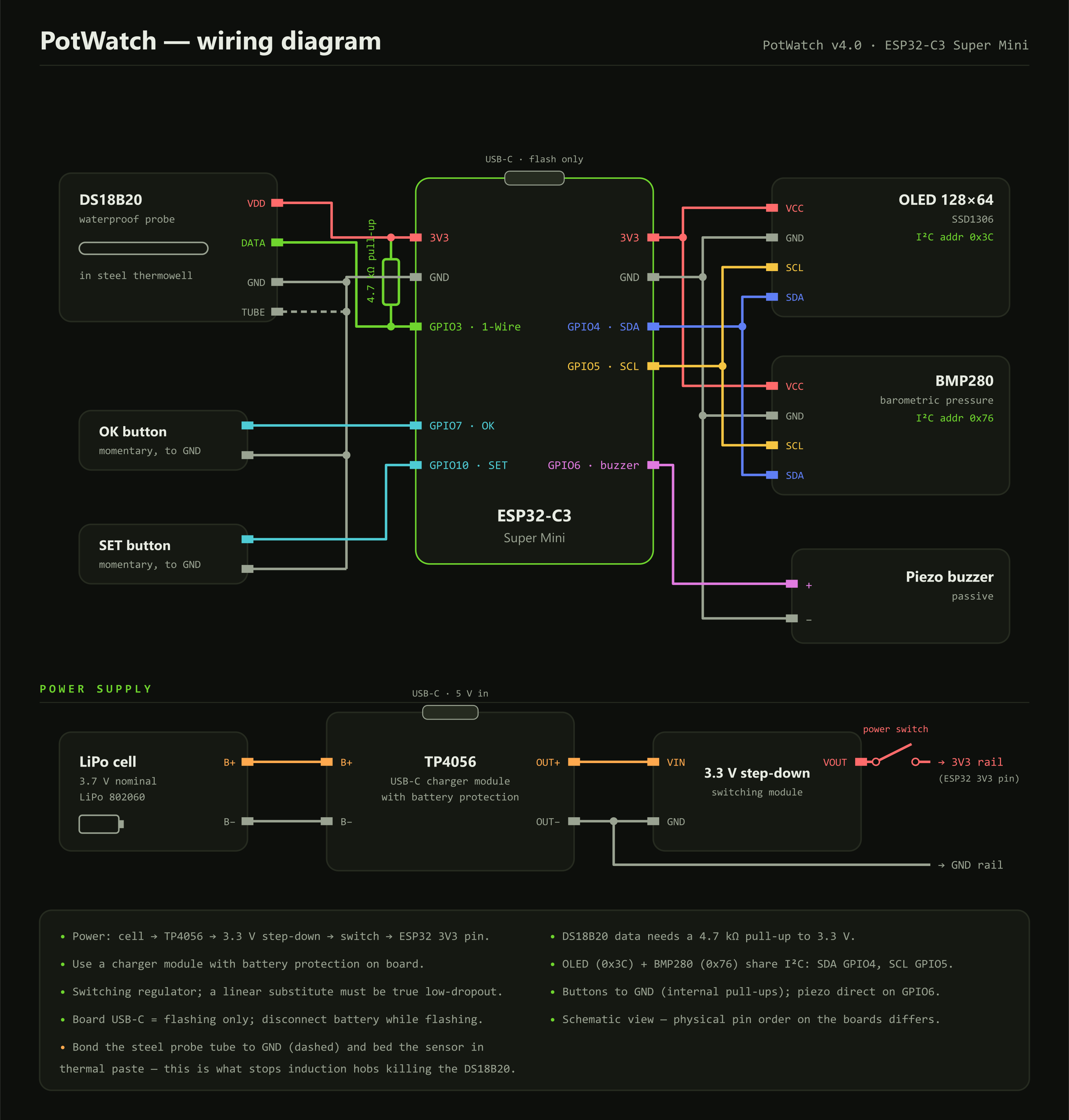
    DS18B20 data     GPIO3, with a 4.7 kOhm pull-up to 3V3

    Thermowell body  GND

    I2C SDA          GPIO4   (display and barometer share the bus)

    I2C SCL          GPIO5

    SSD1306 OLED     I2C address 0x3C

    BMP280           I2C address 0x76

    Piezo buzzer     GPIO6, driven directly

    OK button        GPIO7 to GND, internal pull-up

    SET button       GPIO10 to GND, internal pull-up

    The piezo needs no transistor and no flyback diode — it is a capacitive load, not an inductive one. The buttons need no external resistors; the internal pull-ups do the job.

    Build the power chain

    LiPo cell → TP4056 → 3.3 V step-down → self-locking switch → board 3V3 pin

    The board’s own USB-C port is for flashing only. Charging goes through the TP4056, and that module must be the variant with battery protection — the one with the extra DW01 chip and four output pads, not the bare charger that looks almost identical.

    Check the regulator output with a meter before it meets the board. The prototype measures 3.296 V. If you substitute the regulator, the test is not whether it fits the shell: does it work from an input below 4.2 V, and does it draw microamps rather than milliamps at rest? The LM2596 and MP1584 need 4.5 V in and never start from one cell; the AMS1117 browns out at half charge; the LM2596 also idles at about 5 mA, which flattens a 1000 mAh cell in a week doing nothing.

    Flash the firmware

    Install the Arduino IDE, the Espressif ESP32 board package, and five libraries: OneWire, DallasTemperature, Adafruit GFX, Adafruit SSD1306 and Adafruit BMP280.

    Keep potwatch.ino in a folder called potwatch, select your ESP32-C3 board and upload over USB-C. If the serial monitor stays silent afterwards, enable USB CDC On Boot — on the C3 this catches almost everyone once.

    Disconnect the battery while flashing.

    Calibrate, then use it

    Boil a pot of water and watch the live reading on the calibration screen. Set the number you want the countdown to start at — the true boiling point if you want a boil detector, or lower if you would rather start when the water is merely lively. Hold SET to save. It goes into non-volatile storage and survives firmware upgrades.

    After that: clip it on, drop the probe in, pick a preset, walk away. Every preset and threshold is a constant at the top of the sketch, so if three minutes is not your soft egg, change one number and reflash.

View all instructions

Enjoy this project?

Share

Discussions

Does this project spark your interest?

Become a member to follow this project and never miss any updates