 Ilia Kuzmin
-
1Build instructions
Print the four parts
enclosure (60.5 × 84 × 24 mm), cover (59 × 84 × 3 mm), holder1 and holder2. Standard slicer settings, no supports, no tuned profile.
Material matters more than settings here. The device spends its working life directly above a pot of steam, and PLA softens around 60 °C — which rising steam reaches without difficulty. The prototype is fibre-reinforced ABS with an ASA cover; ASA also shrugs off UV, which suits the part facing the room. Both want an enclosed printer. On an open-frame machine, PETG is the sensible compromise.
The screw holes are undersized on purpose — 2.8 mm for the M3s, 1.8 mm for the display screws — so the screws cut their own thread. No nuts, no heat-set inserts. Filaments shrink differently, so test one hole before printing the lot. If you prefer inserts, open the holes out; the STEP files are editable.
Prepare the probe
This is the step that decides whether your device is still working in a year.
Cut the stainless thermowell to suit your pot — long enough to reach the water with the body clipped to the rim, short enough not to touch the base. Fill the well with thermal paste, ordinary CPU heatsink compound, and slide the DS18B20 probe in until it bottoms out. Wipe the excess.
Then solder a thin wire from the steel tube itself to GND. If you cannot solder to the tube, clamp the wire under the threaded fitting — the connection needs to be electrical, not pretty.
Skipping either half of this works fine on gas or radiant hobs and destroys sensors on induction. The first project log explains why.
Wire the electronics
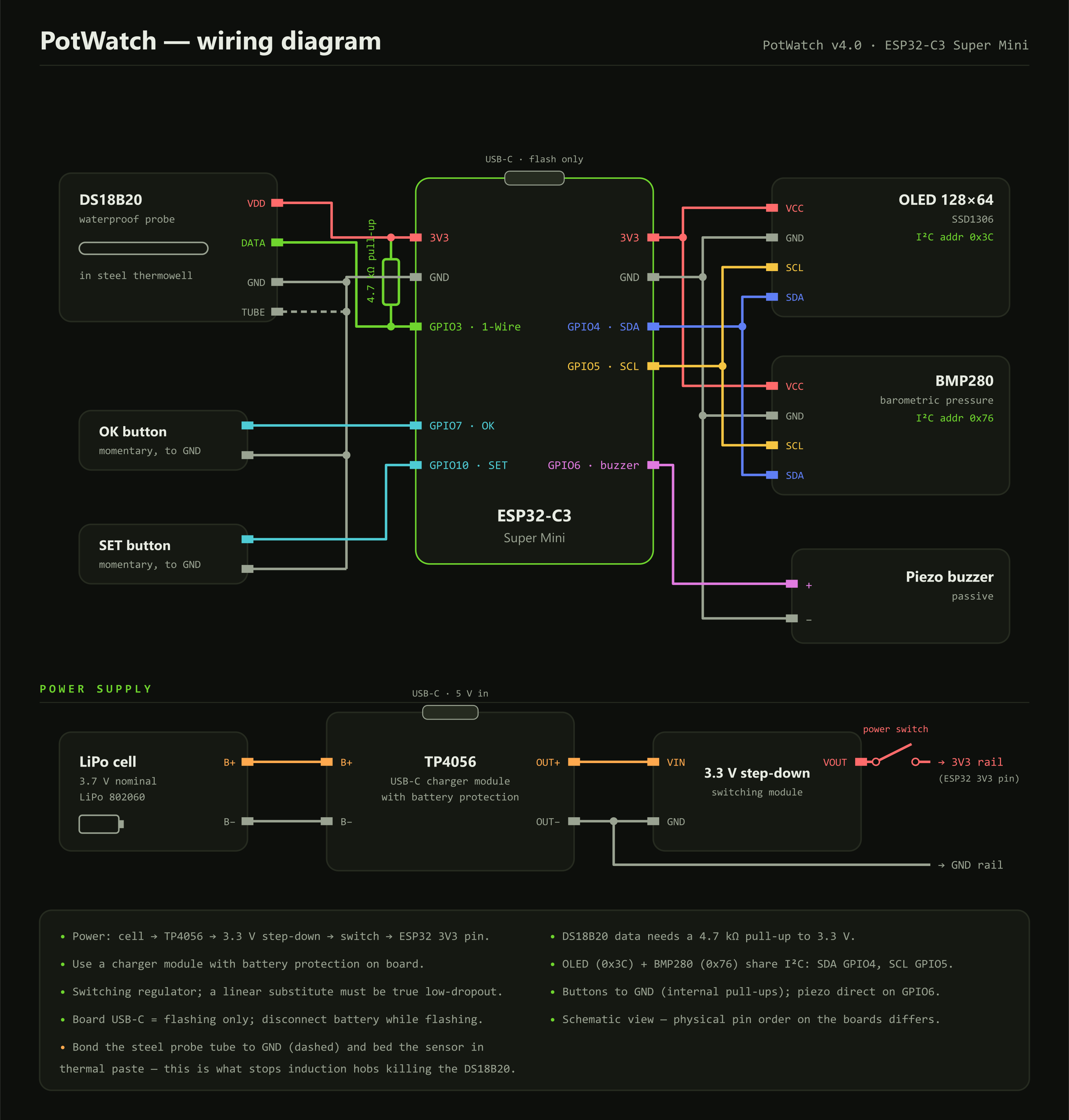
DS18B20 data GPIO3, with a 4.7 kOhm pull-up to 3V3
Thermowell body GND
I2C SDA GPIO4 (display and barometer share the bus)
I2C SCL GPIO5
SSD1306 OLED I2C address 0x3C
BMP280 I2C address 0x76
Piezo buzzer GPIO6, driven directly
OK button GPIO7 to GND, internal pull-up
SET button GPIO10 to GND, internal pull-up
The piezo needs no transistor and no flyback diode — it is a capacitive load, not an inductive one. The buttons need no external resistors; the internal pull-ups do the job.
![]()
Build the power chain
LiPo cell → TP4056 → 3.3 V step-down → self-locking switch → board 3V3 pin
The board’s own USB-C port is for flashing only. Charging goes through the TP4056, and that module must be the variant with battery protection — the one with the extra DW01 chip and four output pads, not the bare charger that looks almost identical.
Check the regulator output with a meter before it meets the board. The prototype measures 3.296 V. If you substitute the regulator, the test is not whether it fits the shell: does it work from an input below 4.2 V, and does it draw microamps rather than milliamps at rest? The LM2596 and MP1584 need 4.5 V in and never start from one cell; the AMS1117 browns out at half charge; the LM2596 also idles at about 5 mA, which flattens a 1000 mAh cell in a week doing nothing.
Flash the firmware
Install the Arduino IDE, the Espressif ESP32 board package, and five libraries: OneWire, DallasTemperature, Adafruit GFX, Adafruit SSD1306 and Adafruit BMP280.
Keep potwatch.ino in a folder called potwatch, select your ESP32-C3 board and upload over USB-C. If the serial monitor stays silent afterwards, enable USB CDC On Boot — on the C3 this catches almost everyone once.
Disconnect the battery while flashing.
Calibrate, then use it
Boil a pot of water and watch the live reading on the calibration screen. Set the number you want the countdown to start at — the true boiling point if you want a boil detector, or lower if you would rather start when the water is merely lively. Hold SET to save. It goes into non-volatile storage and survives firmware upgrades.
After that: clip it on, drop the probe in, pick a preset, walk away. Every preset and threshold is a constant at the top of the sketch, so if three minutes is not your soft egg, change one number and reflash.
PotWatch — the timer that waits for the boil
A clip-on kitchen timer that starts its countdown when the water hits a temperature you chose, not when you press a button.
Discussions
Become a Hackaday.io Member
Create an account to leave a comment. Already have an account? Log In.