 Maxim Pavlov
Driving a stepper motor is often one of the first practical electronics experiments. The 28BYJ-48 motor and its ULN2003 driver board are inexpensive, widely available, and simple to control from an Arduino. Paul Gallagher's 28BYJ-48 project in LittleArduinoProjects provides a useful introduction to the motor, the driver board, the coil sequence, and the required connections.
This article examines the same circuit from a power perspective. We use PSU-EXT to measure its current and power consumption in different operating modes, including holding with one or two energized coils and running the motor at different step rates.
Setup
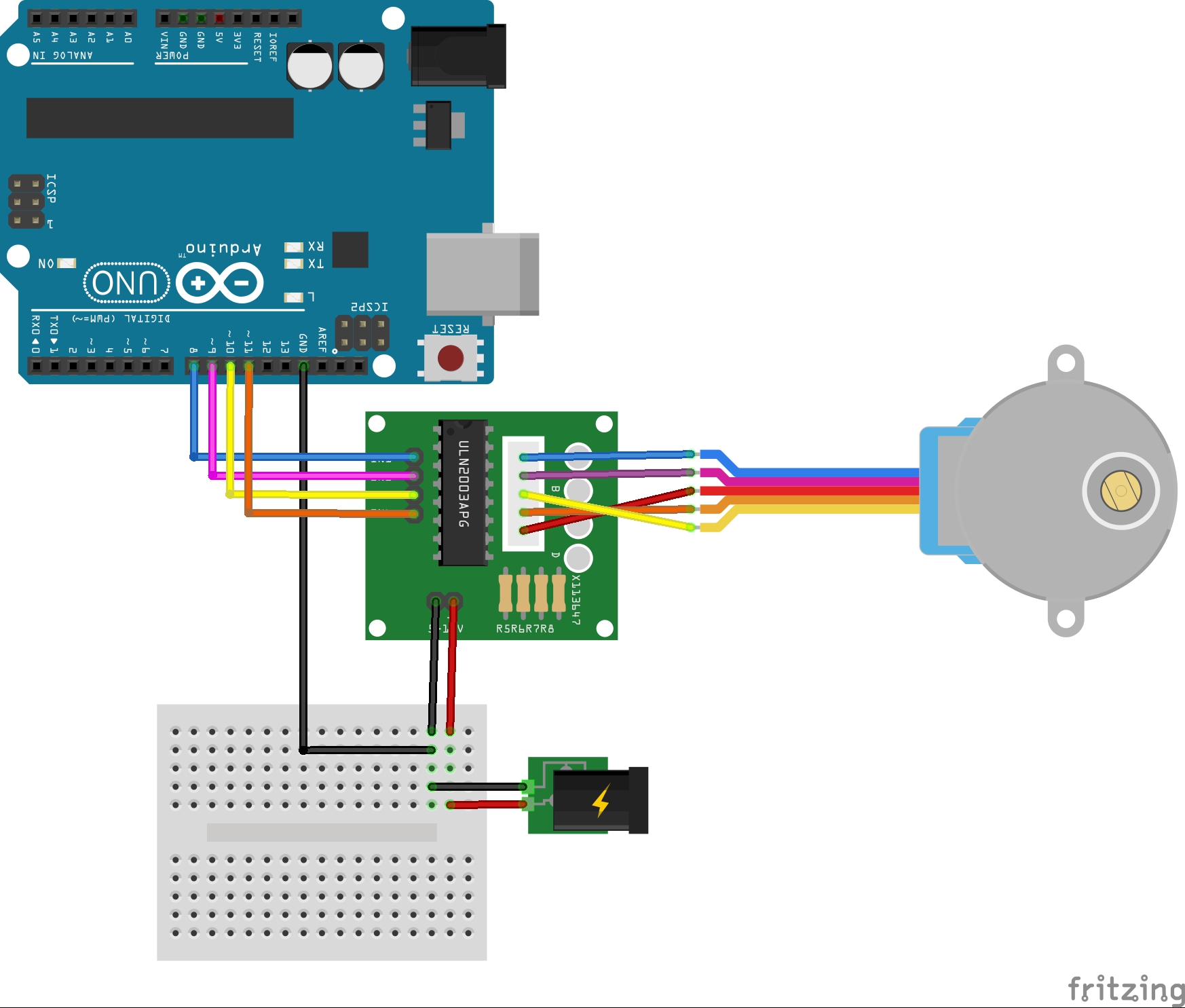
Figure 1. Basic 28BYJ-48 and ULN2003 wiring. Copyright © Paul Gallagher. Image from LittleArduinoProjects, used under the MIT License
The Arduino ground is connected to the ULN2003 module ground, as shown in Figure 1. The Arduino and PSU-EXT are each powered over USB. The motor receives 5 V from the bench power supply through PSU-EXT.
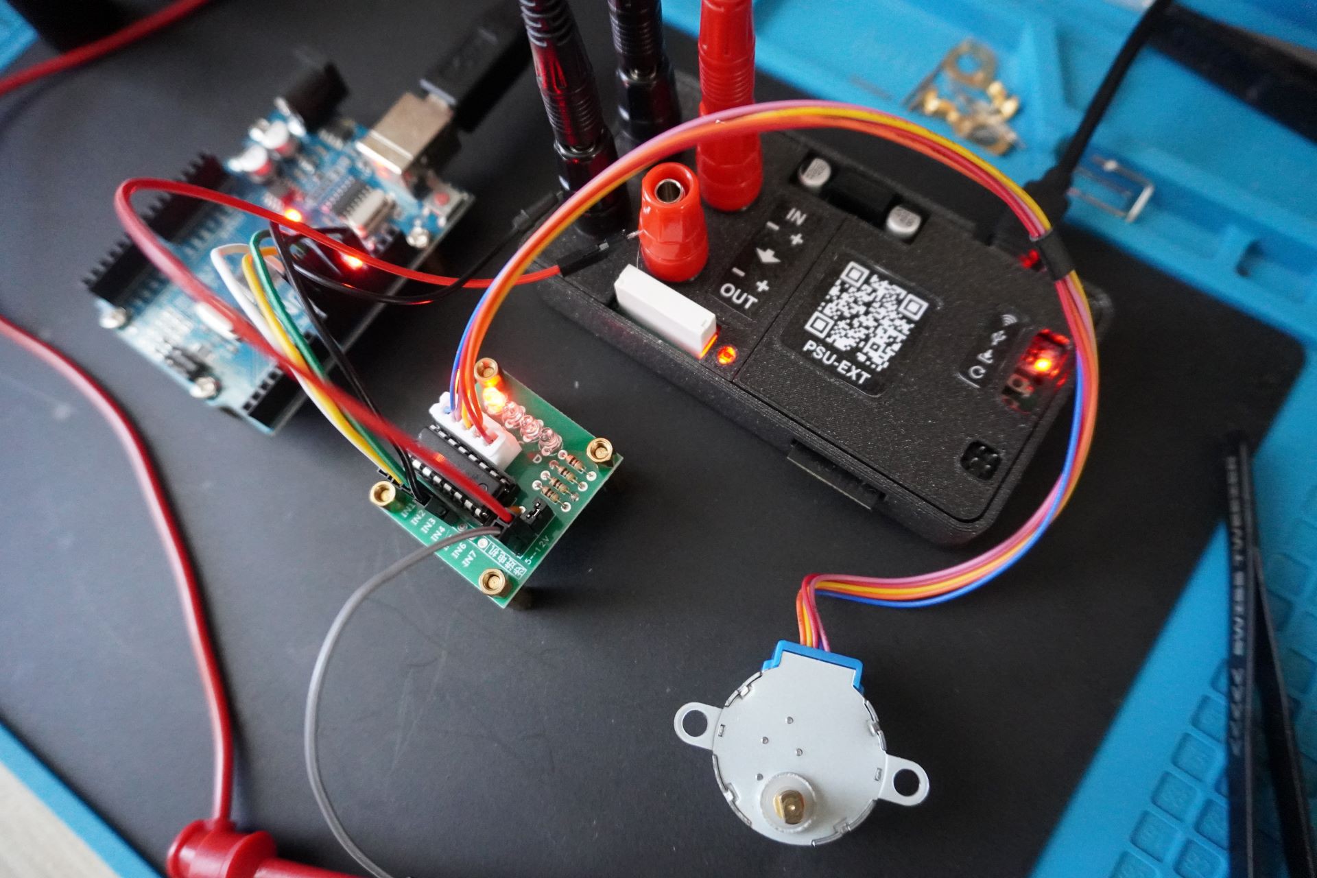
A Rigol DM858E digital multimeter is connected in series with the motor circuit. It provides an independent current measurement for comparison with the PSU-EXT reading. The complete current path is the bench power supply, PSU-EXT, ULN2003 driver, 28BYJ-48 motor, DM858E current input, PSU-EXT return, and bench power supply return.
Arduino Control Sketch
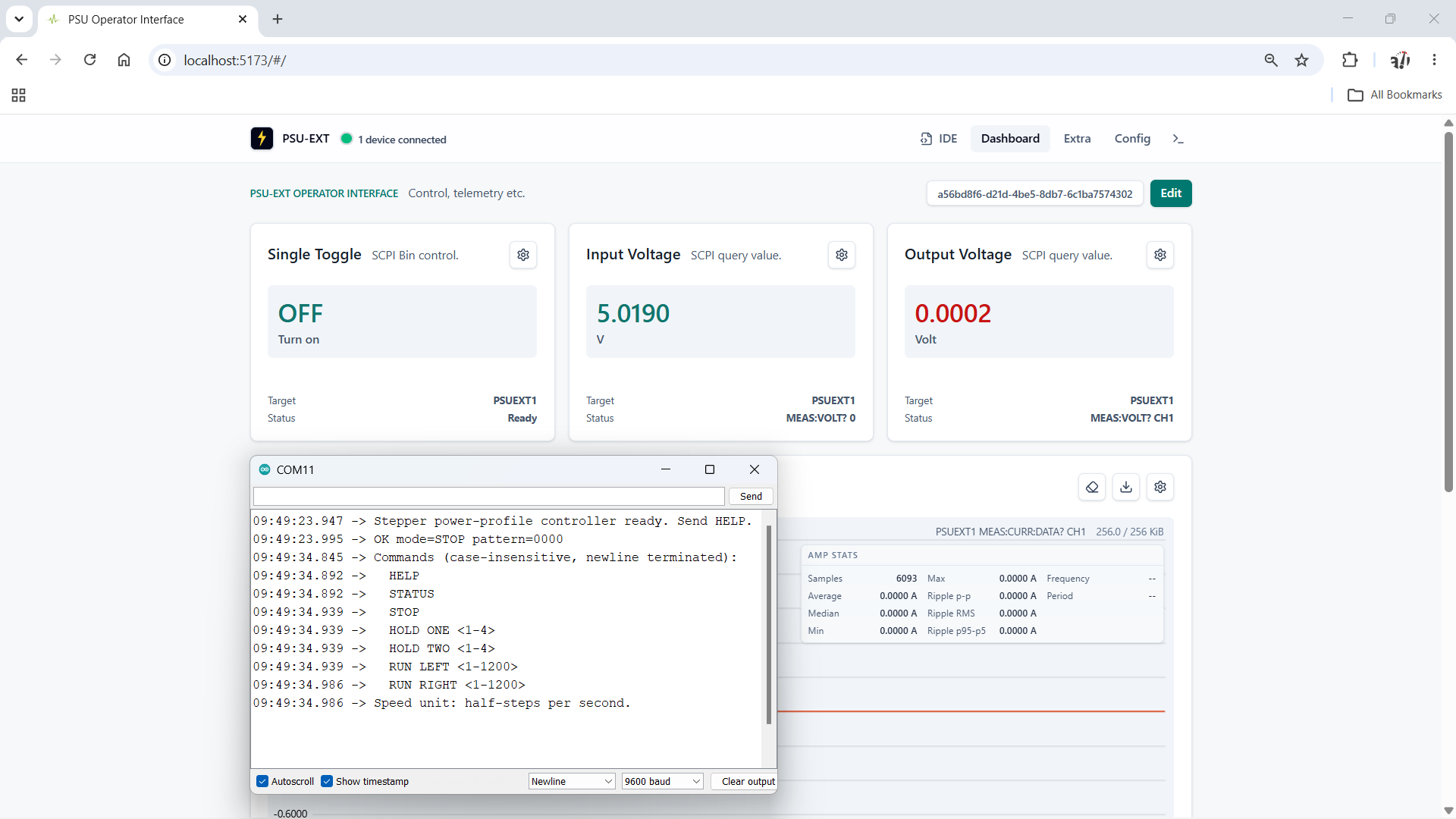
The Arduino sketch drives the motor with an eight-state half-step sequence and accepts newline-terminated commands over a 9600-baud serial connection. This lets us select a repeatable coil state or running speed while recording the electrical measurements.
| Command | Function |
|---|---|
| HELP | Lists the available commands. |
| STATUS | Reports the current mode, coil pattern, direction, and speed. |
| STOP | De-energizes all four driver inputs. |
| HOLD ONE <1-4> | Holds one of four positions with one coil energized. |
| HOLD TWO <1-4> | Holds one of four positions with two adjacent coils energized. |
| RUN LEFT <1-1200> | Advances through the sequence at 1 to 1200 half-steps per second. |
| RUN RIGHT <1-1200> | Traverses the sequence in reverse at 1 to 1200 half-steps per second. |
The running range starts at one half-step per second because zero represents the stopped state and cannot be used to calculate a step interval. The upper limit of 1200 half-steps per second was selected as an experimental ceiling. A common 5 V 28BYJ-48 datasheet specifies a no-load starting frequency above 600 Hz and a no-load running frequency above 1000 Hz. Extending the test range to 1200 half-steps per second lets us examine the motor near and beyond that documented region. It is not a guaranteed operating speed, and the sketch applies the requested speed without an acceleration ramp. The observed shaft direction depends on the motor wiring and the side from which it is viewed.
Testing Hold Modes: One or Two Coils
The sketch provides one-coil and two-coil hold modes. Each mode has four selectable electrical positions. These numbers identify positions in the drive sequence, not absolute positions of the geared output shaft.
| Command | IN1 | IN2 | IN3 | IN4 | Energized coils |
|---|---|---|---|---|---|
| HOLD ONE 1 | 1 | 0 | 0 | 0 | 1 |
| HOLD ONE 2 | 0 | 1 | 0 | 0 | 1 |
| HOLD ONE 3 | 0 | 0 | 1 | 0 | 1 |
| HOLD ONE 4 | 0 | 0 | 0 | 1 | 1 |
| HOLD TWO 1 | 1 | 1 | 0 | 0 | 2 |
| HOLD TWO 2 | 0 | 1 | 1 | 0 | 2 |
| HOLD TWO 3 | 0 | 0 | 1 | 1 | 2 |
| HOLD TWO 4 | 1 | 0 | 0 | 1 | 2 |
One-coil hold provides the lower-power reference. Two-coil hold energizes two windings at the same time and should draw more current while providing greater holding torque. Measuring all four positions also shows any differences between the individual windings and driver channels.
HOLD ONE 1
The
HOLD ONE 1
command keeps the first ULN2003 input active and energizes one motor winding continuously. The motor remains stationary while the energized winding produces holding torque.
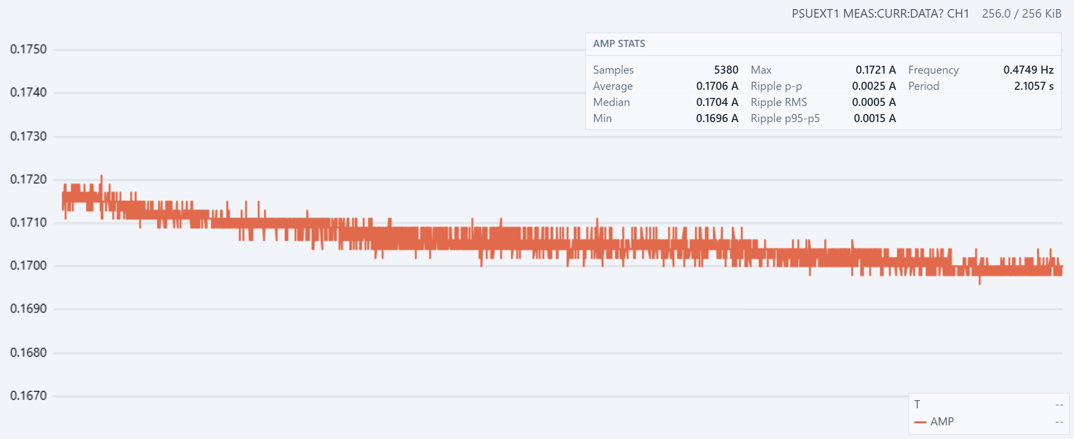
Figure 2. PSU-EXT current measurement during HOLD ONE 1. The recorded minimum is 0.1696 A, the maximum is 0.1721 A, and the average is 0.1706 A.
The full recorded span is 2.5 mA, or about 1.45% of the maximum. The sustained current level falls by less than this because the minimum and maximum include short spikes. The downward trend is consistent with thermal settling. Current heats the energized copper winding, and copper resistance increases with temperature. The higher resistance reduces the current from a constant-voltage supply. The ULN2003 output transistor also warms up, which can increase its voltage drop and reduce the voltage available to the winding.
The current stabilizes when the heat generated in the winding and driver is balanced by the heat transferred to the surrounding air and hardware.
The HOLD ONE 2 to HOLD ONE 4 measurements show no substantial difference from HOLD ONE 1, so their charts are not repeated here. Within the resolution and variation of this test, these windings and ULN2003 channels have similar current profiles.
HOLD TWO 1
The
HOLD TWO 1
command activates IN1 and IN2, energizing two adjacent motor windings while the shaft remains stationary.
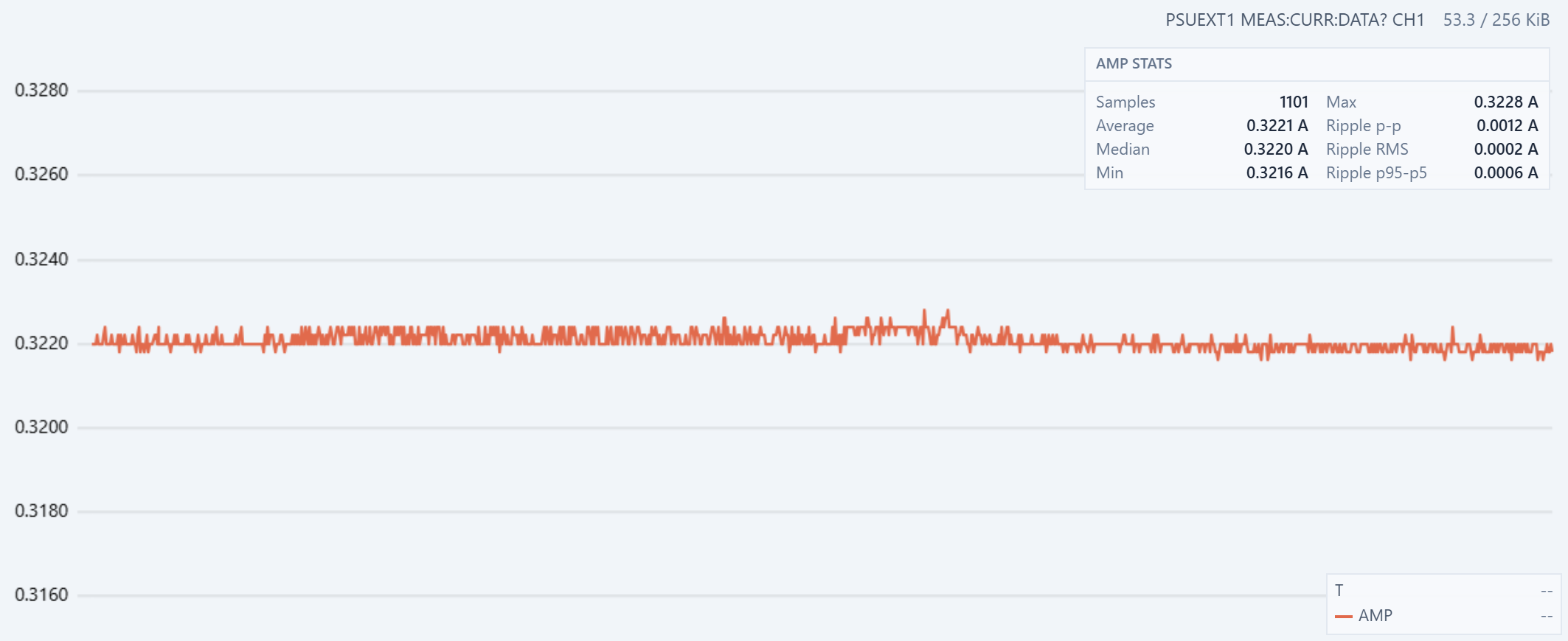
Figure 3. PSU-EXT current measurement during HOLD TWO 1. The average is 0.3221 A, the minimum is 0.3216 A, and the maximum is 0.3228 A.
The two-coil average is 0.1515 A higher than the 0.1706 A measured during HOLD ONE 1, an increase of about 88.8%. It is close to, but not exactly, twice the one-coil current. Shared wiring and return-path resistance, driver voltage drops, and small differences between windings and ULN2003 channels can all reduce the current from the ideal doubled value.
The trace is stable around 0.322 A. Its total recorded span is only 1.2 mA, or about 0.37% of the average. This level also agrees with the upper current plateau observed when the running half-step sequence energizes two coils.
Testing Run Modes at Minimum and Maximum Speed
RUN LEFT 1
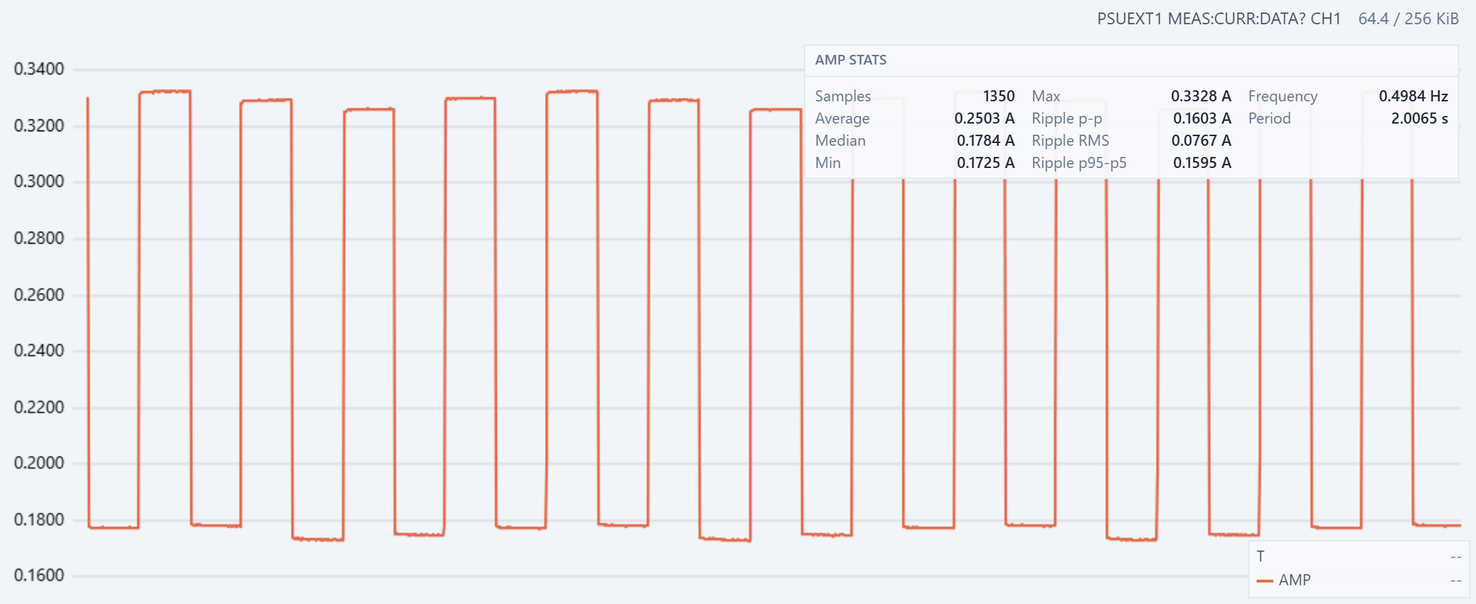
Figure 4. Current during RUN LEFT 1. PSU-EXT reports a minimum of 0.1725 A, a maximum of 0.3328 A, an average of 0.2503 A, and a waveform frequency of 0.4984 Hz.
At one half-step per second, each state lasts for one second. The half-step sequence alternates between one energized coil and two energized coils. The current therefore alternates between approximately 0.175 A and 0.330 A. The same coil-count state returns every two steps, giving an expected current-magnitude period of two seconds, or 0.5 Hz. The measured 0.4984 Hz agrees with this sequence timing.
The high and low plateaus vary slightly as the sketch moves through the four windings and ULN2003 channels. This is consistent with the small channel differences observed in the hold tests. The average is also close to the midpoint between the one-coil and two-coil levels because both states have the same duration.
RUN LEFT 1200
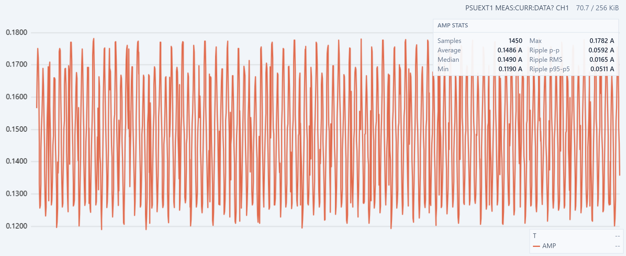
Figure 5. Sampled current during RUN LEFT 1200.
At 1200 half-steps per second, each state lasts about 833 µs. The sequence still alternates between one-coil and two-coil states, so its current-magnitude component is expected at 600 Hz. The complete eight-state electrical sequence repeats at 150 Hz. These changes are much faster than the plotted samples (100 Hz) can resolve.
The sample points are distributed evenly across the captured current range, and the sampled pattern repeats with consistent spacing. This shows that the acquisition is observing a stable periodic process and is not dominated by a few isolated spikes. However, the connected points represent samples taken at different phases of the switching cycle. The apparent cycles are a sampled pattern, not a complete reconstruction of the underlying 600 Hz current waveform or its true cycle time.
The reported average is about 0.15 A, compared with 0.2503 A at one half-step per second, a reduction of about 40%. The motor windings are inductive, so their current cannot reach the steady one-coil or two-coil level during an 833 µs state. Back electromotive force from a rotating motor can reduce it further. However, this current trace alone does not prove that the rotor remained synchronized with the commanded 1200 half-steps per second
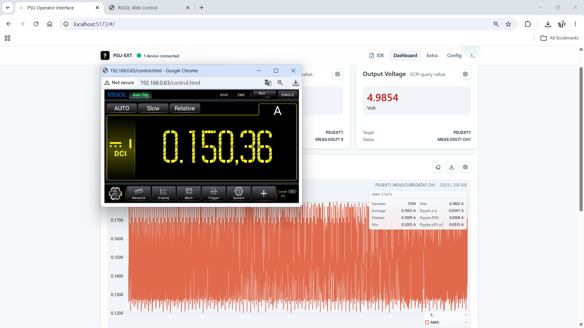
Figure 6. Independent current comparison during RUN LEFT 1200. PSU-EXT reports a 0.1503 A average over 5150 samples, while the Rigol DM858E reads 0.15036 A.
The displayed values differ by 0.00006 A, or 0.06 mA, which is about 0.04%. This close agreement shows why the limited waveform resolution does not make the measurement useless. The samples cover many switching cycles and are distributed across different phases rather than concentrated around one part of the cycle. They therefore produce a representative average even though they do not reconstruct each current pulse.
The independent DM858E result supports using the PSU-EXT capture to compare operating modes, estimate average power, observe thermal drift, and detect larger changes in operating state.
Transition From RUN LEFT 50 to RUN LEFT 1200
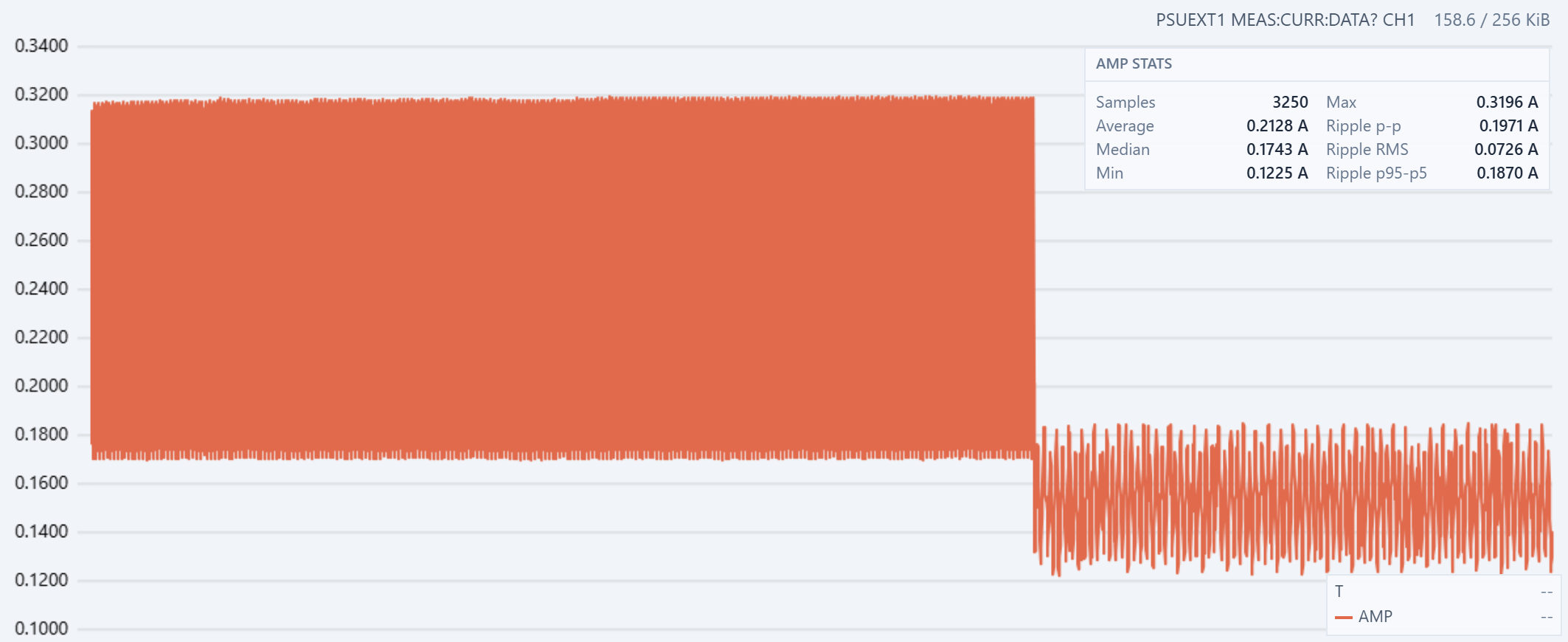
Figure 7. Current-envelope change when the command switches from RUN LEFT 50 to RUN LEFT 1200.
At 50 half-steps per second, each drive state lasts 20 ms. This gives the energized winding current time to approach the one-coil and two-coil levels seen in the slower tests. The left side of Figure 7 spans approximately 0.169 A to 0.320 A, an envelope width of about 0.151 A.
The command then changes directly to 1200 half-steps per second. Each state is now about 833 µs, which is 24 times shorter. The current envelope drops immediately to approximately 0.123 A to 0.184 A. Its midpoint falls by about 37%, and its width contracts from about 0.151 A to 0.061 A.
Winding inductance limits how quickly current can rise. At 1200 half-steps per second, the drive moves to the next state before the active winding currents can approach their steady values. If the rotor accelerates with the command, the higher back electromotive force also opposes the applied voltage and reduces current. These effects lower both edges of the envelope and reduce the difference between the one-coil and two-coil states.
The sharp boundary shows that the electrical load responds immediately to the speed command. After the transition, the lower current envelope remains stable, with no visible long settling period.
Full-Speed Direction Reversal
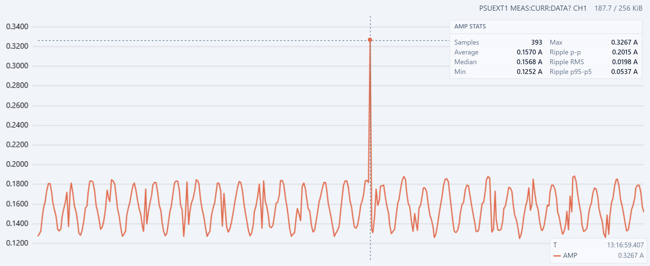
Figure 8. Current during an immediate change from RUN LEFT 1200 to RUN RIGHT 1200. The reversal produces a measured peak of 0.3267 A.
The current envelopes before and after the command are similar. Direction alone therefore has little effect on the steady high-speed current in this test. The capture average is 0.1570 A, while the reversal reaches 0.3267 A. The transient is about 2.1 times the average current and approaches the two-coil current seen at low speed.
The electrical sequence reverses immediately, but the rotor and gearbox cannot reverse their motion instantly. Rotor inertia keeps the motor moving in the original direction while the reversed magnetic field applies braking torque. During this brief braking and re-acceleration interval, the relationship between winding current, rotor position, and back electromotive force changes sharply. The resulting transient allows the supply current to rise well above the normal 1200-half-step-per-second envelope.
This is a reason to avoid an immediate direction change in normal motion control. A controlled profile should decelerate the motor, reverse at or near zero speed, and then accelerate in the opposite direction. That reduces current transients, mechanical shock, and the risk of losing steps.
Conclusion
This evaluation produced one counterintuitive result and one intuitive result. The counterintuitive result is that a higher commanded step rate draws less average current. The measured average falls from about 0.250 A at one half-step per second to about 0.150 A at 1200 half-steps per second. At high speed, each drive state is too short for the winding current to reach its steady value. Winding inductance limits the current rise, and back electromotive force can reduce it further. This lower current does not imply higher efficiency or greater mechanical output. It also means a smaller torque margin.
The intuitive result is that an immediate direction change at full speed produces a current spike. The rotor must first lose its existing motion and then accelerate in the opposite direction. The reversal reaches 0.3267 A, compared with an average of 0.1570 A during the surrounding high-speed operation. A controlled deceleration and acceleration profile would reduce this transient.
The captured power profile closely follows the current profile. The WEP305D linear bench power supply used in this experiment shows minimal voltage drop while the load remains below 0.5 A. With the supply voltage nearly constant, power is approximately a scaled version of current because
P = V × I
The current reduction at high speed and the reversal spike therefore appear in the power data with the same shape and relative size.
In this experiment PSU-EXT adds the time dimension to measurements from a conventional bench supply. While Rigol multimeter confirmed the average current, PSU-EXT showed how the load changed during warm-up, speed changes, and direction reversal. Recording voltage, current, and power together provides a more complete view of device behavior than a single power supply front-panel reading.
In the future we might to introduce an Afterburner acquisition mode for faster measurements. The target is about 400 measurements per second from one selected analog-to-digital converter (ADC) channel, either voltage or current, while the other channel remains inactive. This planned mode would provide more detail for short events such as the direction-reversal transient.
If you like the article, pleaser follow current project and PSU-EXT on Crowd Supply for further project updates.
Discussions
Become a Hackaday.io Member
Create an account to leave a comment. Already have an account? Log In.