 martybanovic

Main function
Main function of the device is to detect a IR radiaton which sends HIGH output from NS312. This will lead to flip one NE555 timer on (and the LED as well). Main point is to hold the LED in ON state when the human is detected and turn it OFF with delayed turn-off after exiting the toiltet.
The device consists of passive (RC) THT/SMD components to minimize the size of PCB and active components: timers, transistors and NS312 sensor. The first approach was to test the schematic and then make a PCB.
For now, it wont have housing in case I came with an idea to improve it, and I want to include battery with charger module and a booster. With this consideration I can make the proper housing in the future.
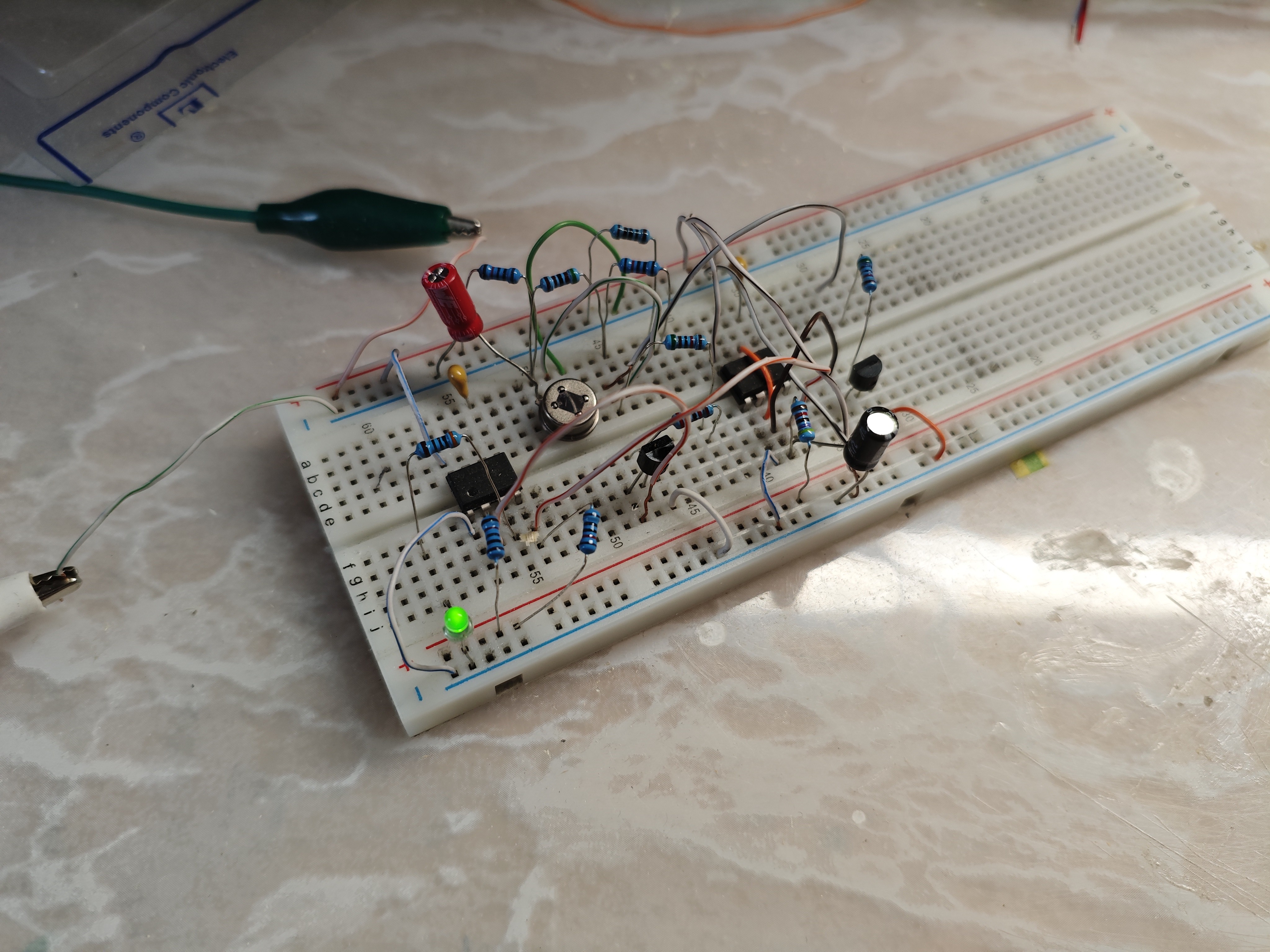
Parts description
PCB - making process
That part of making a routes was made with KiCad with respect to holes spacing of universal PCB I used (2,54mm from every hole). First thing was to redraw schematic from paper to program and then make the PCB prototype, then safe front and back of the PCB in PDF file to use it as reference to draw the routes (red parts are for SMD resistors).
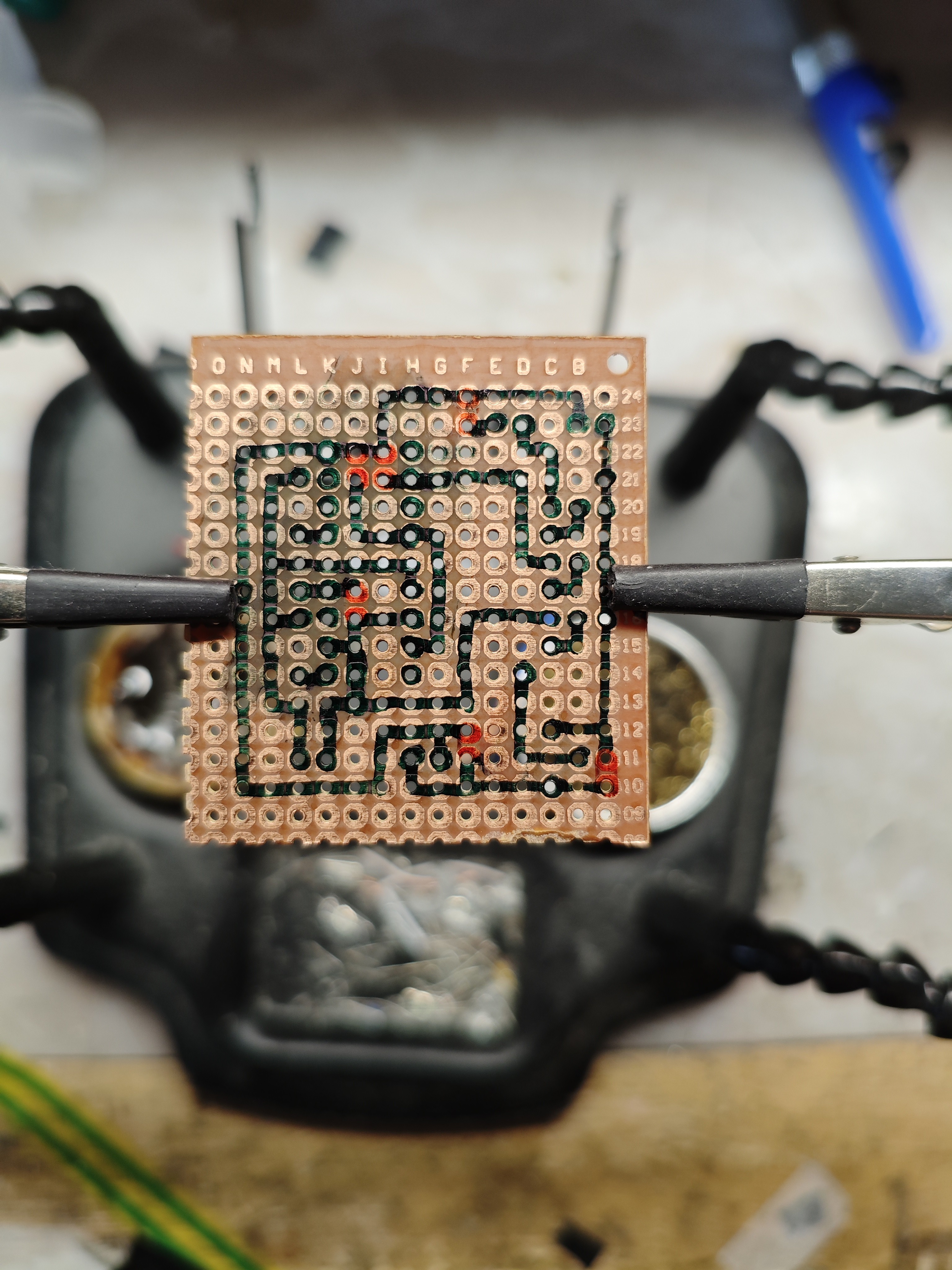 | 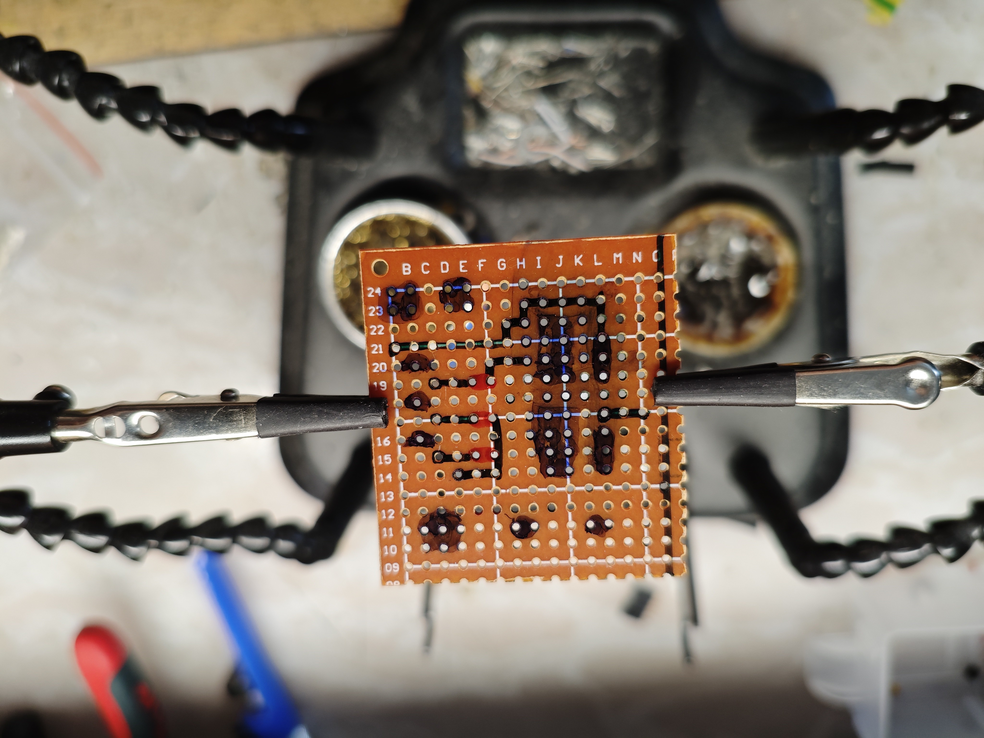 |
Soldering:
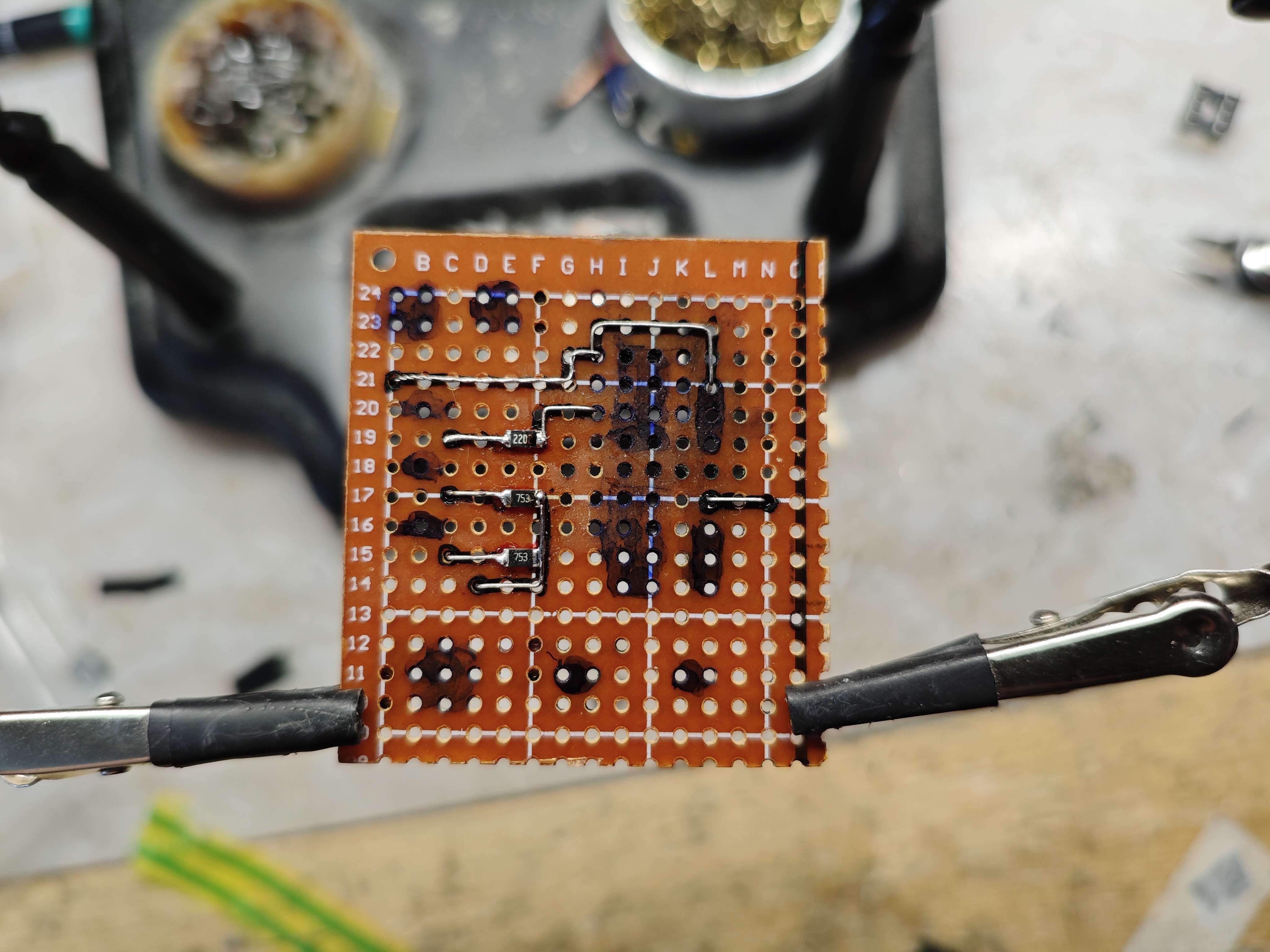
First soldered were the SMD components with airwires (with the fact that holes shared with other components were soldered with them later)
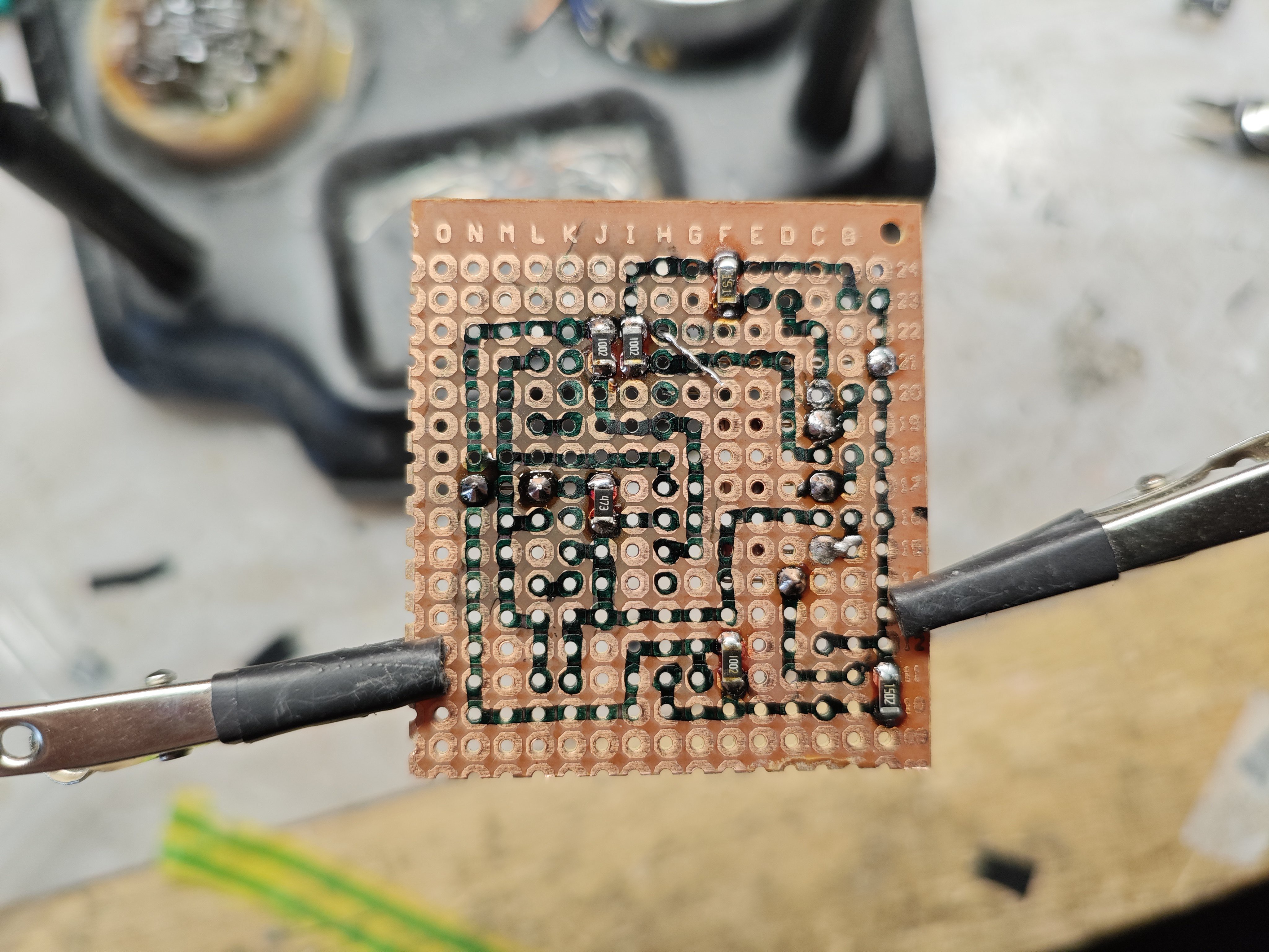 |  |
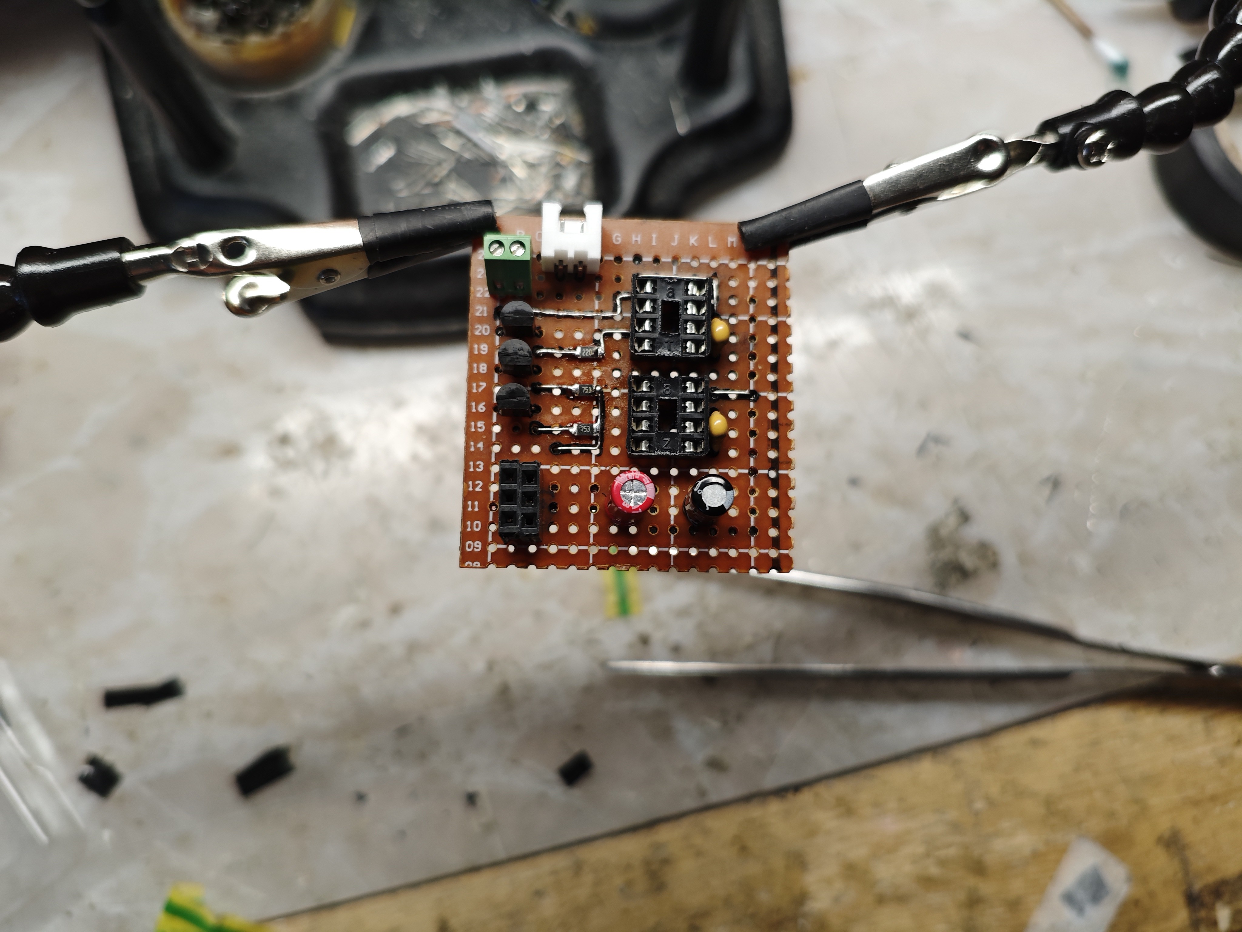
Then the other THT components were soldered in specific order to solder everything without an obsticle in the way.
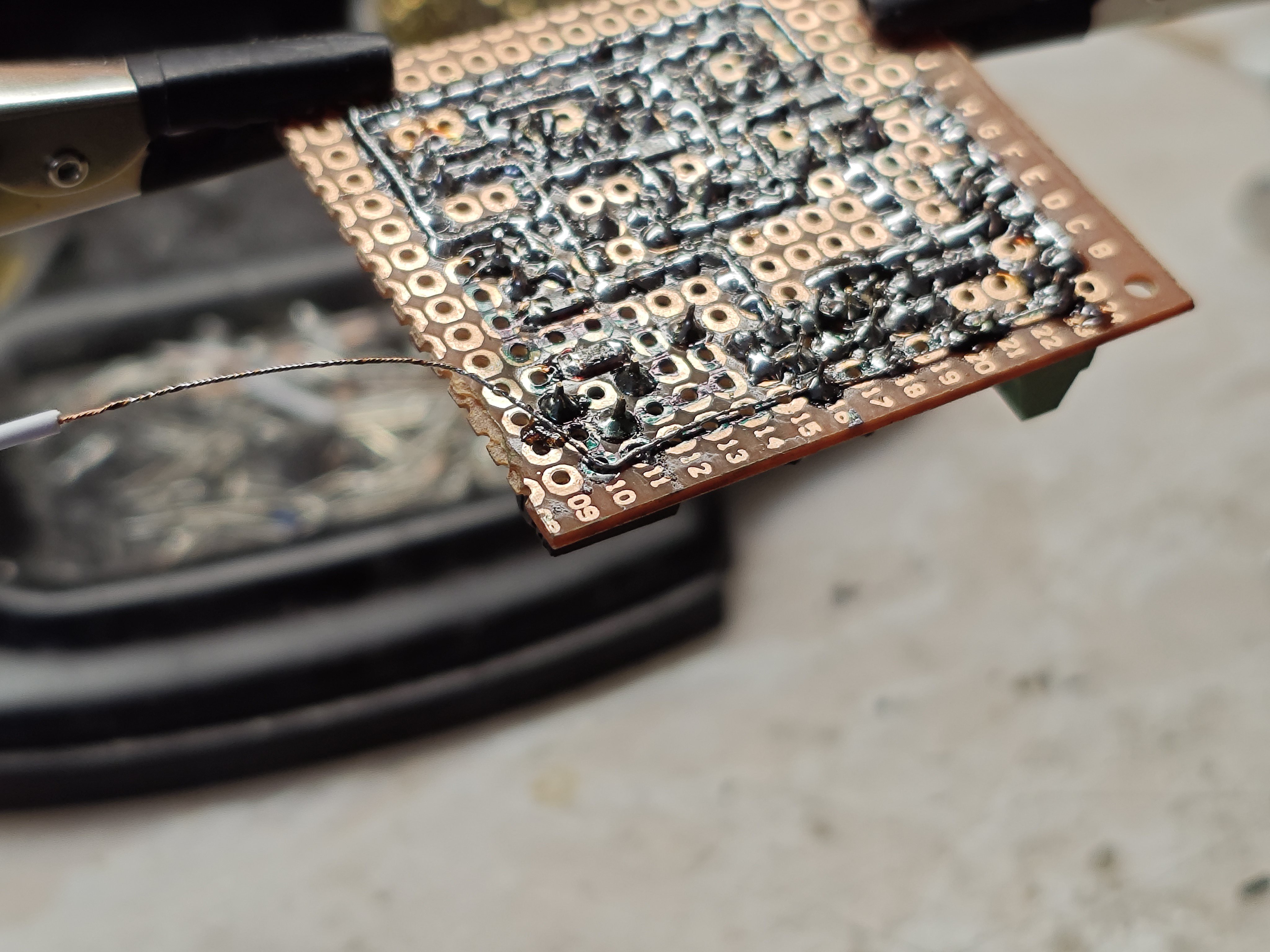
The routes were made with twisted thin copper wires covered with solder, creating paths from one point to another. The routes were alo made based on reference of saved PDF file (I have to mention that during this procedure I noticed the pinout of the sensor was wrong and I had to change it in KiCad and redraw lines on the board...)
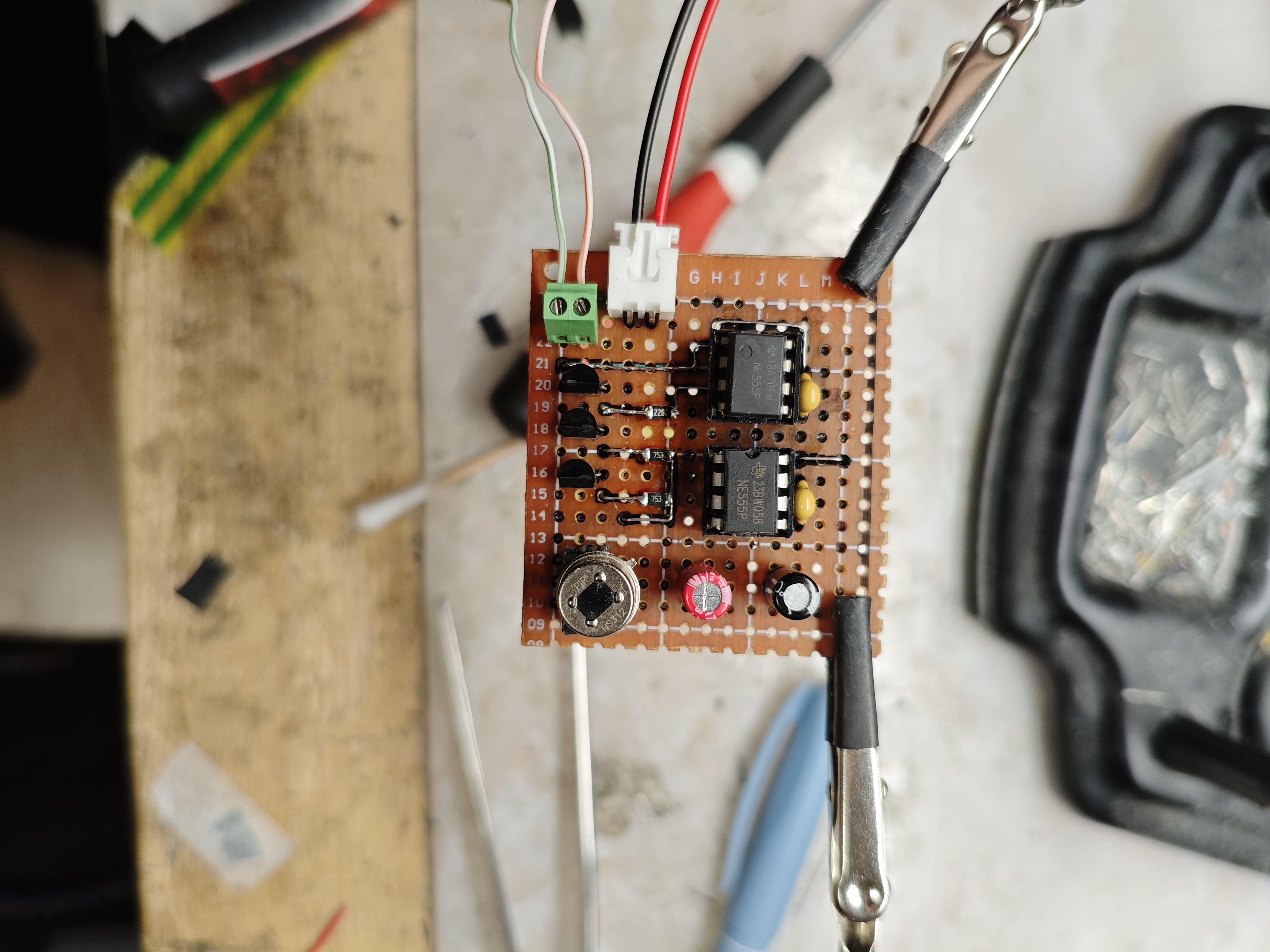
After finishing, the back of the PCB was cleaned with a isopropanol and the circuit was tested.
NE555 as RS flip-flop
First NE555 is used as a RS flip-flop circuit to ensure that the LED will be ON. The configuration is pretty easy considering the official datasheet as reference to ensure the right connections. TRIGGER pin is a low active pin (U2 < 1/3 Ucc) with a pull-up resistor and RESET pin has the same configuration. Transistors are used as saturating switches.
If the NS312 sensor detects IR radiation, it will change its output state to HIGH with duration of 2 seconds. This will be enough to turn on transistor Q1 connecting reference point of the circuit with TRIG pin which changes the output state of the timer to ON. That will turn on transistor Q2 and the LED. Timer will be held at that state until the RESET pin will be activated with low input.
R5 is 150Ω even though the resistor should be 130Ω. The reason for this is very reasonable: I dont have 130Ω resistor so I just grabbed the closest value that I had in reach of my hands...
But it is not a problem. 130Ω resistor came from calculation where Uled = 2,6V (measured with LCR-T7 tester) and Uce (of Q2) = 0V: R5 = (Ucc - Uled) / I , I = 0,018A (wanted the LED to be bright enough). When the device was powered on, the LED had arroud 2,66V using 150Ω resistor. The current then will be I = (5 - 2,66) / 150, or 0,0156A. The current flowing through LED is slightly smaller than planned, albeit the LED will still provide enough brightness. And with this current it will last longer.
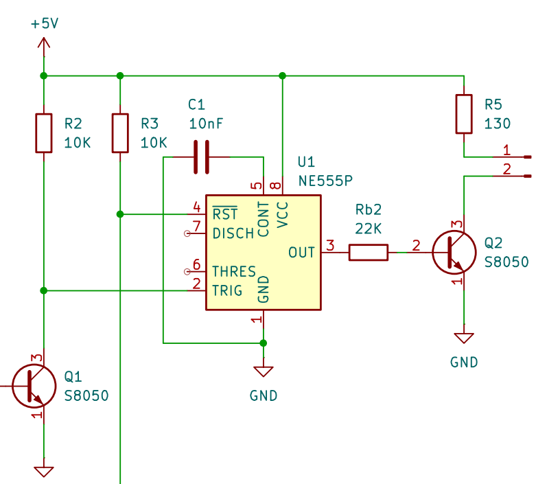
Reference: https://www.alldatasheet.com/datasheet-pdf/view/2001479/TI/NE555.html
NE555 as delay turn-off switch
This timer is used as delayed turn-off switch whose output is tied up to RESET pin of the first timer (now I am thinking the pull-up resistor was unnecessary...). The reference came from the link bellow with slight adjustment.
In operation when NS312 is detecting a human (and IR radiation), the transistor is actively turning on and acts as low-resistance bypass across capacitor ensuring it wont charge. The time that needs to be achieved to charge the capacitor and change the state of the timer is stated with...
Read more »