 stemforge.phil
Five Sensors, One Flight: Recreating a Water Rocket’s Path Without GPS (even when Hitting the 16 g Wall)
Pump a soda bottle to 65 PSI, pull the pin, and the whole flight is over in seconds. No single sensor can tell you what happened in those seconds. The gyroscope drifts, the magnetometer is noisy, the accelerometer only knows “push,” and the barometer gets fooled by rushing air. But get them all talking to each other, and the HYPER S3 ROCKET can rebuild the entire flight in 3D, from pad to touchdown, without a single GPS fix.
Five sensors, one truth: rebuilding the flight from the inside
Here’s the part we’re most proud of. Every position in the 3D recreation (4:20) comes from the rocket’s own sensors working together. No GPS, no ground tracking, just correlated data and physics (5:16).
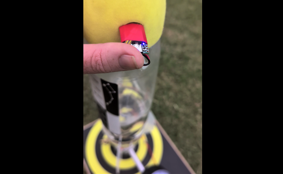
Step 1: Find the horizon. Before you can say where a rocket went, you have to know which way is level. On its own, each sensor gets this wrong in its own way. The gyroscope reacts instantly to every twist and roll, but its small errors build up over time and the horizon slowly tilts away. The magnetometer gives an absolute reference to magnetic north that never drifts, but it’s too noisy to trust moment to moment. Fused together (5:33), each corrects the other. The gyro supplies the fast, smooth motion, and the magnetometer keeps pulling it back to a fixed heading. The result is a stable, level horizon reference that holds through stages of boost, coast and tumble.
Step 2: Point the acceleration in the right direction. The accelerometer measures thrust along the rocket’s own body, and the rocket is pitching, rolling and weathercocking into the wind the whole time. Using the fused attitude from Step 1, every acceleration sample is rotated out of the rocket’s frame and into the oval’s frame: up, downrange and crosswind. Gravity is removed, and what’s left is the rocket’s true motion over the ground.
Step 3: Integrate to velocity, then to displacement. Integrate that world-frame acceleration once and you get velocity. Integrate again and you get displacement, mapped onto real XY coordinates across the oval (5:24). This is dead reckoning, the same principle that guided aircraft and submarines long before satellites.
Step 4: Cross-check against the barometer. Double integration is unforgiving, since any small error grows fast. So the vertical axis is checked against the barometric altimeter. Each sensor keeps the others honest: the barometer anchors height, and the inertial data exposes the altimeter’s pressure spikes at high speed (8:44).
Gyro (fast) + Magnetometer (stable) ➔ Level horizon & attitude            ↓
Accelerometer (body frame) ➔ rotated to oval frame ➔ minus gravity            ↓
∫ ➔ Velocity   ∫∫ ➔ Displacement (X, Y, Z)            ↓
Barometer cross-check ➔ 3D flight path
The payoff: a 3D flight recreation that follows the crosswind drift across the oval, with apogee within ±0.9 m and the landing point within ±4 m (9:49). That’s from a 4 gram board riding a fast soda bottle.
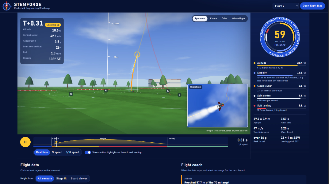
For students, this is the magic moment. Calculus stops being abstract when the integral of your rocket’s acceleration draws your rocket’s path across the screen, then shows the stages one by one and even recreates the tumble to the ground. Want a softer landing? - sounds like a plan.
Discussions
Become a Hackaday.io Member
Create an account to leave a comment. Already have an account? Log In.