 Aditya56h
Work date:14 September 2026
The enclosure work has expanded from one 64-channel unit into a mechanical plan for multiple synchronized modules.
There are
two different uses of the word “master” in this project. Inside one Analog Board, the eight ADS1299 devices use one master and seven slaves in the analog bias/reference topology. At enclosure level, a master module and slave modules describe complete 64-channel units. These are separate relationships.
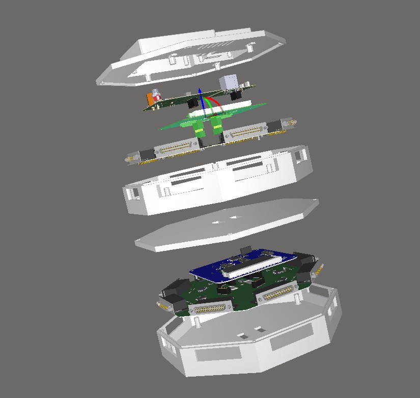
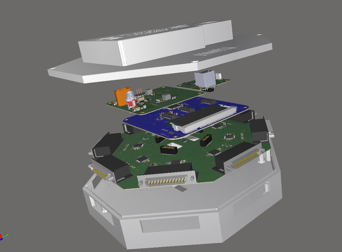
The **master module** contains all four PCBs:
- Analog Board;
- Digital EEG Board;
- Top Power Board;
- Top I/O Board.
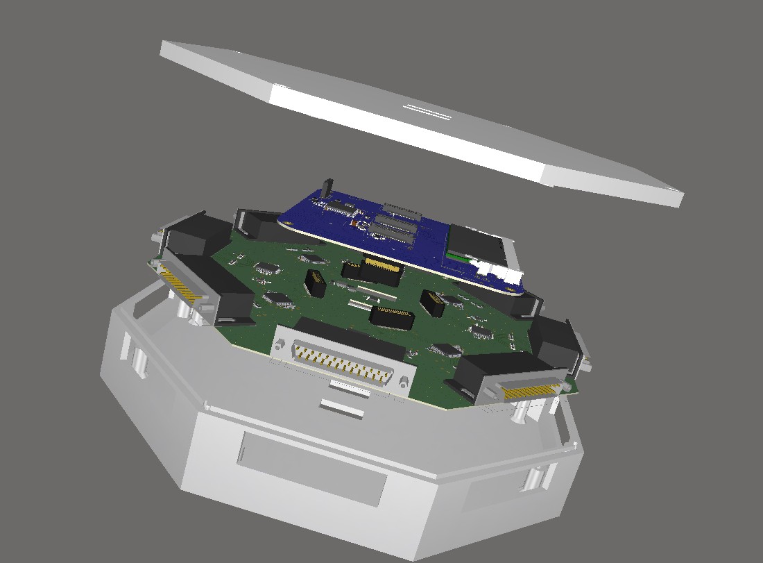
A **slave module** contains its own Analog Board and Digital EEG Board but does not duplicate the Top Power or Top I/O boards. Its lid is therefore simpler and only needs the mechanical and vertical-stack passages required by the digital interconnect.
The first multi-module target is one master plus one slave, which gives a 128-channel design capacity. After timing and data transport work with two modules, the long-term target is one master plus three slaves for 256 channels.
The exploded CAD views are useful for checking the intended order, but the multi-module electrical links and synchronization have not yet been demonstrated. The next meaningful result will be a shared timing and data test between two physical modules, not simply a larger rendered stack.
Discussions
Become a Hackaday.io Member
Create an account to leave a comment. Already have an account? Log In.