Nick Bild

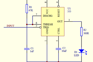
People have managed to get Doom running on just about everything over the years. Calculators, cameras, ATMs, printers, and plenty of other devices that were never intended to run a first-person shooter have all been pressed into service. So I decided to see if I could play Doom on a couple of 555 timers.
Well, sort of.
This project doesn't actually run Doom. Instead, it plays the opening riff from "At Doom's Gate, " the music from the first level of the original game. It does that without a microcontroller, computer, or any software whatsoever.
The circuit uses two 555 timers, some 7400-series logic, a diode matrix, analog switches, and a small audio amplifier. One 555 establishes the tempo while the second generates the actual notes. Everything in between keeps track of where the circuit is in the riff and tells the audio oscillator which pitch it should generate.
How It Works
The circuit can be divided into five main sections:
- Tempo clock
- Sequence counter and decoder
- Diode note matrix
- Pitch selection and audio oscillator
- Audio amplifier
The complete signal path looks like this:
555 tempo clock
|
v
74LS161
binary counter
|
v
74LS154
4-to-16 decoder
|
v
1N4148 diode matrix
|
v
74HCT14
|
v
2 x CD4066
analog switches
|
v
555 audio oscillator
|
v
PAM8302
|
v
speaker
Setting the Tempo
The first NE555 is configured as an astable oscillator. A capacitor repeatedly charges and discharges through a pair of resistors, causing the output on pin 3 to continuously switch between high and low.
This oscillator runs at approximately 7.33 Hz, producing a new clock pulse about every 136 milliseconds.
The 555 isn't producing audio at this point. Its only job is to set the timing of the riff.
A trimmer potentiometer in the timing network makes it possible to fine-tune the clock frequency. I adjusted it while measuring pin 3 with a logic analyzer.
Counting Through the Notes
The clock output goes directly into a 74LS161N, a four-bit synchronous binary counter.
Each clock pulse increments the counter by one:
0000
0001
0010
0011
0100
...
Four bits provide 16 possible states, which works out nicely because this circuit needs 15 positions for the section of the riff being played.
The four counter outputs feed a 74LS154N 4-to-16 decoder. Rather than having to work with a four-bit binary number elsewhere in the circuit, the decoder provides an individual output for each count.
When the counter is at zero, Y0 is selected. At one, Y1 is selected. Then Y2, Y3, and so on.
The 74LS154 outputs are active-low, meaning the currently selected output goes low while all of the others remain high.
That gives the circuit one physical wire corresponding to every position in the sequence.
Making a 15-Step Counter
There are 16 possible counter states, but I only need 15.
The final decoder output, Y15, is therefore used to reset the counter rather than play another note.
Y15 controls a small inverter/driver circuit built from two 2N3904 NPN transistors. When Y15 becomes active, the transistor circuit pulls the active-low CLEAR input of the 74LS161 low.
The counter immediately returns to zero.
A pushbutton connected to the CLEAR input also provides a manual reset.
Storing the Music With Diodes
The counter now knows where it is in the riff, but something still needs to determine which pitch belongs at each position.
That's handled by 15 1N4148 diodes.
There are 15 note positions in the sequence, but only six different pitches. I created six note buses corresponding to those pitches. Each output from the 74LS154 connects through a diode to the bus for the pitch...
Read more »
 Mateo Carabajal
 roelh
roelh
 Roni Bandini