timonsku
-
New set of plants and an easy way to integrate MoRaLiS into a nursery box
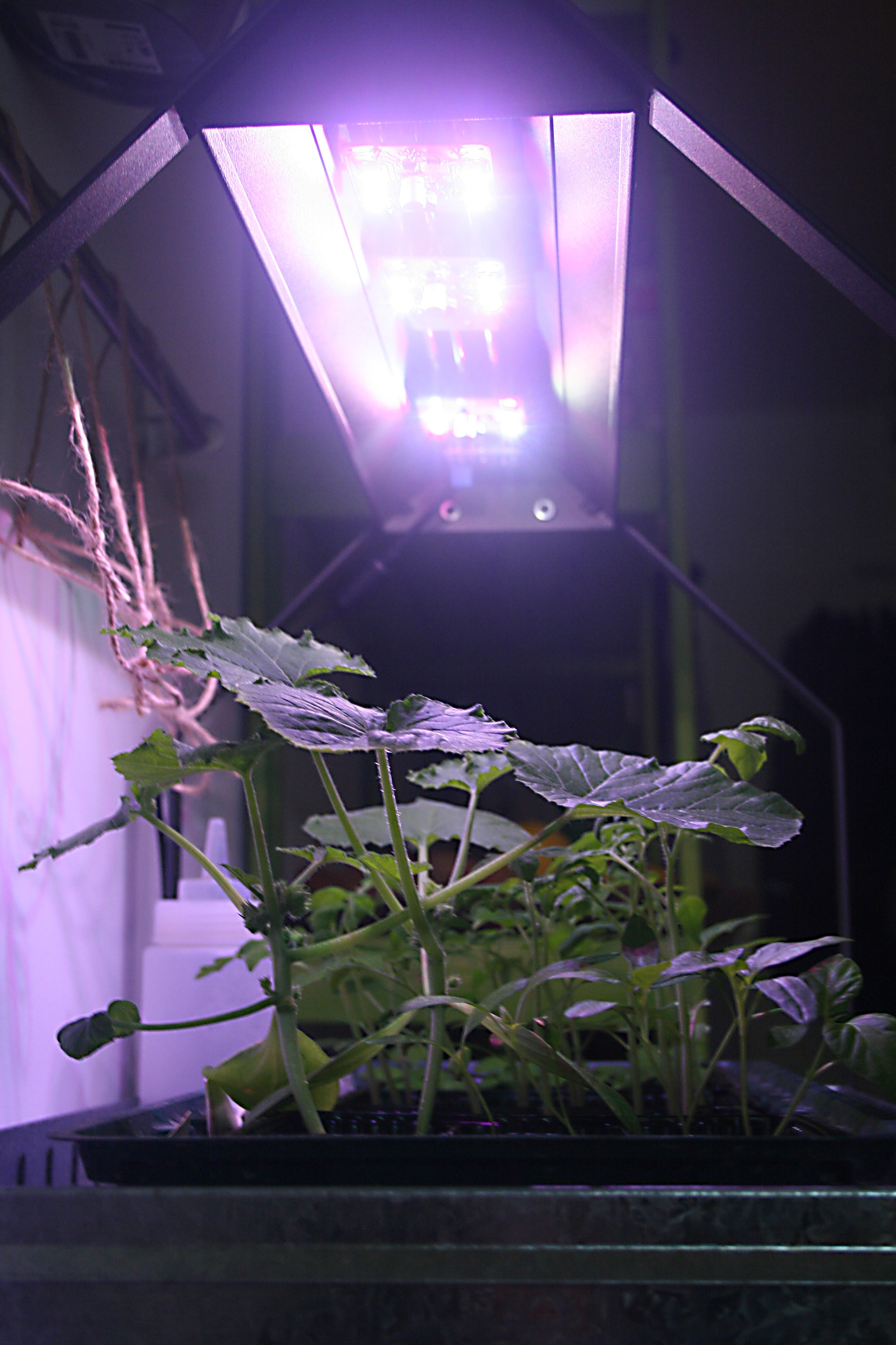
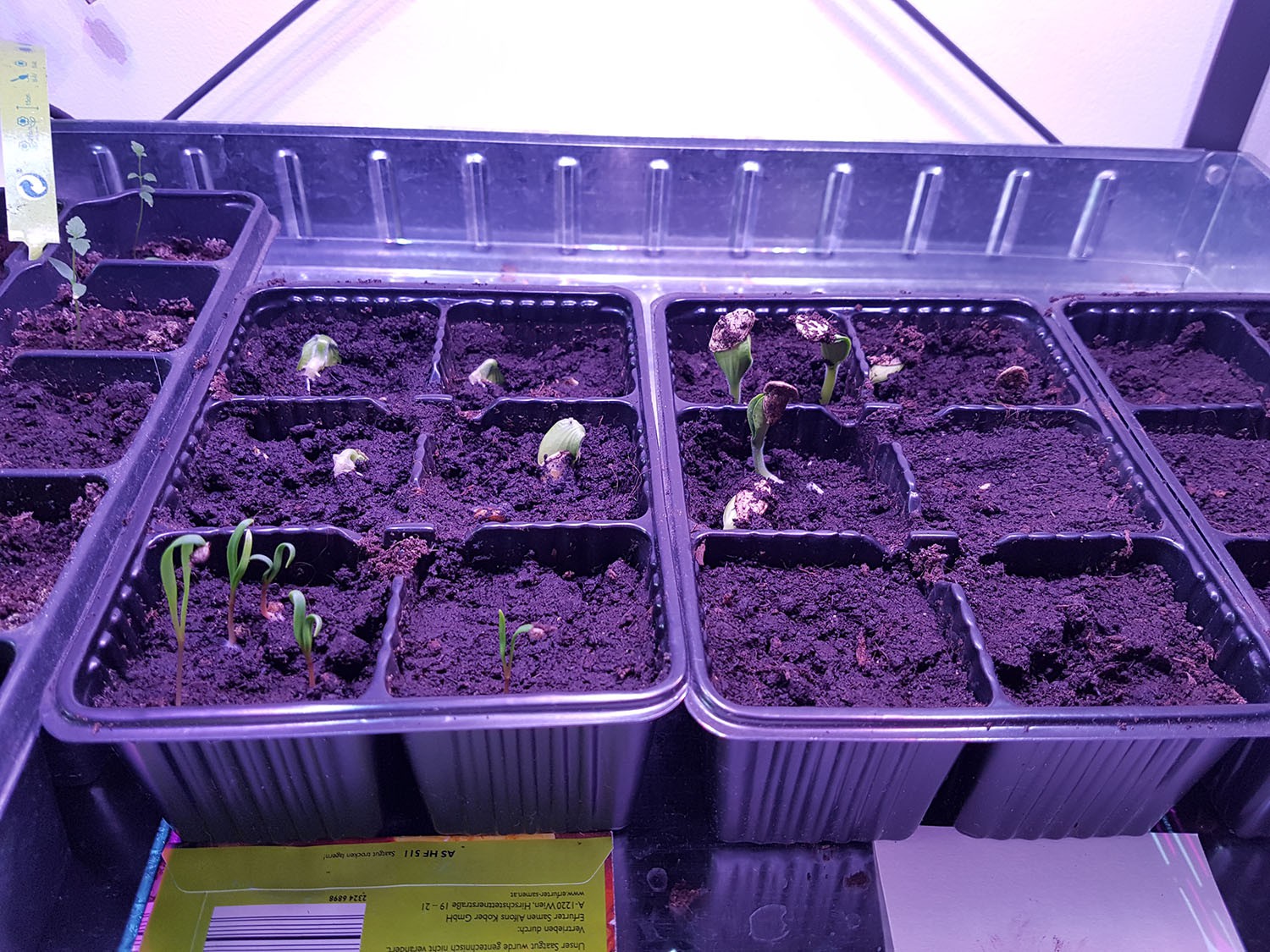
10/15/2017 at 16:59 • 0 commentsI planted a few new seeds to test out the effectiveness of the final modules. I'm also experimenting with simple laser cut carboard shades to decrease the amount of stray light.

Images of installed shades will follow soon. Usually you probably don't want a 4 sides shade but 2 or 3 sided one, 2 sided ones for modules that are located in the middle and 3 sided ones for the two on the outside. Four sided ones only really make sense when you space the module very far apart.
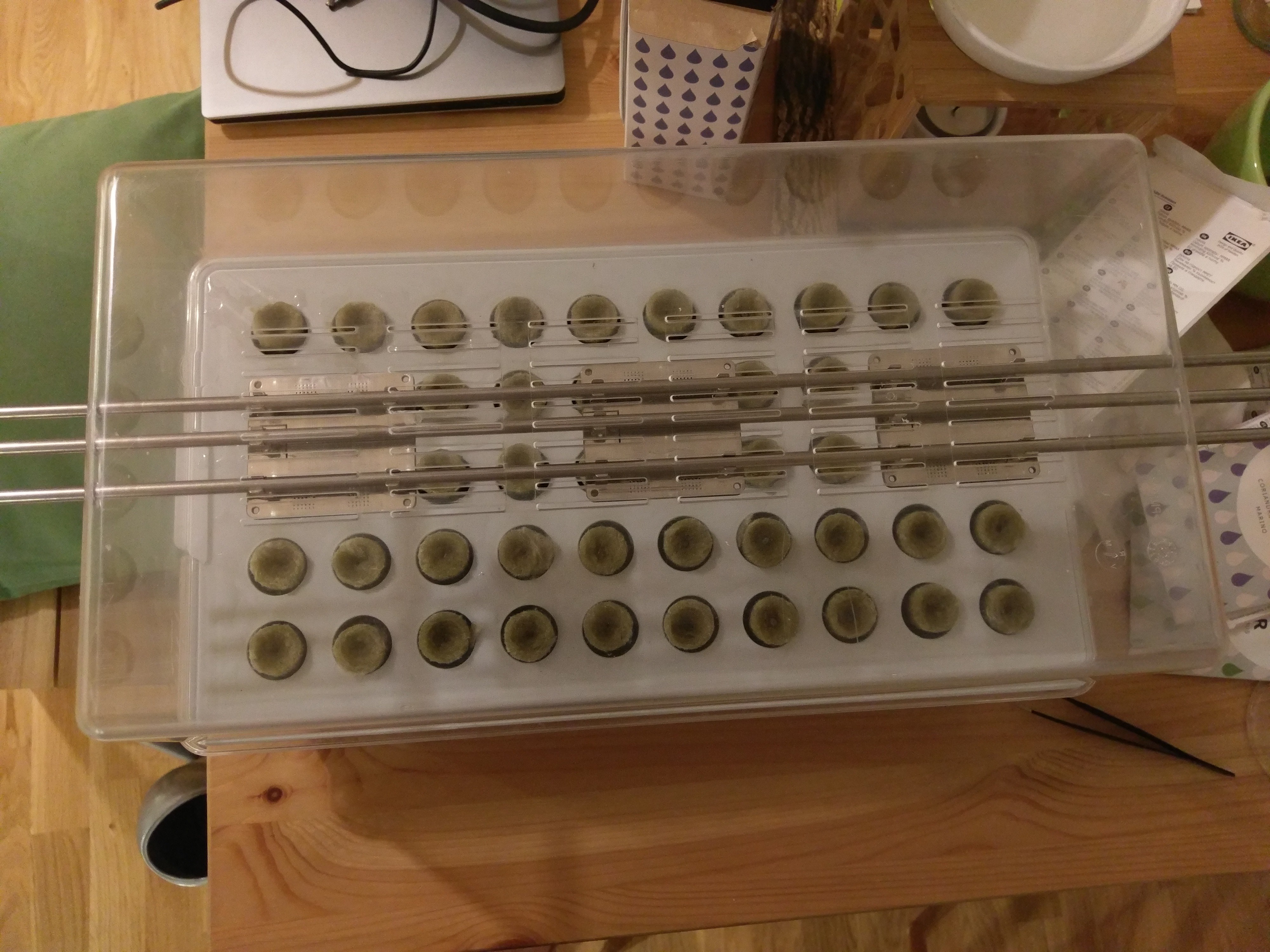
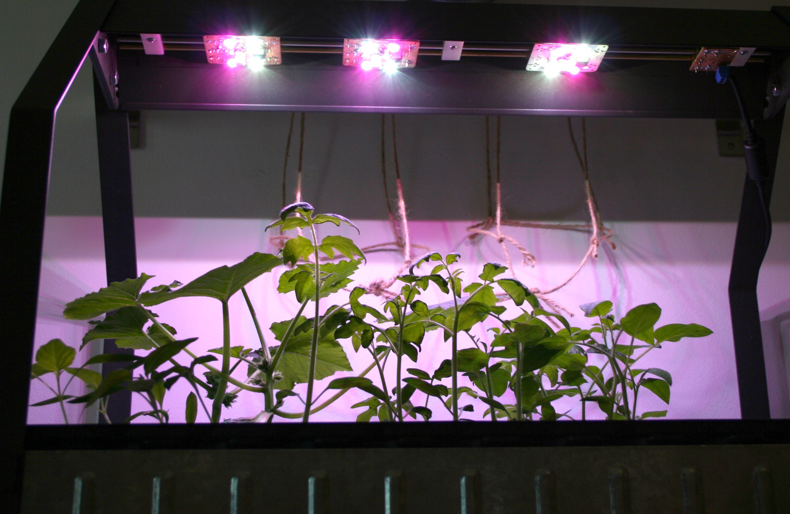
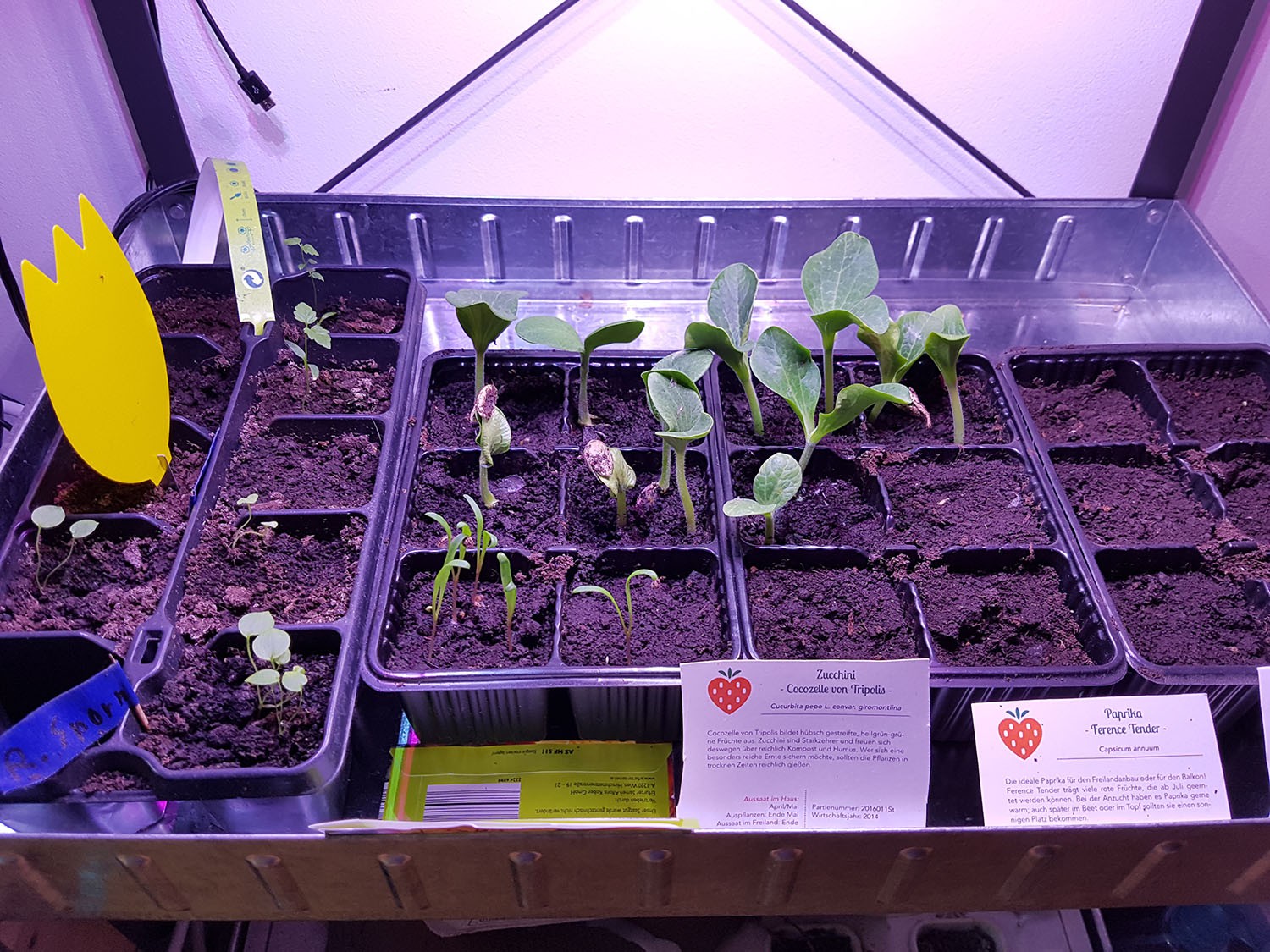
I installed a MoRaLiS set into an Ikea Växer nusery Box but the same thing works for pretty much any nursery box. All I had to do was drill 3 holes into each side of the top. You can use a paper template or just attach the rods a few modules to get the correct spacing and then trace the rods outlines on the top of the box (which is what I did).
Then you just slide the rods in and you're done.![]()
![]()
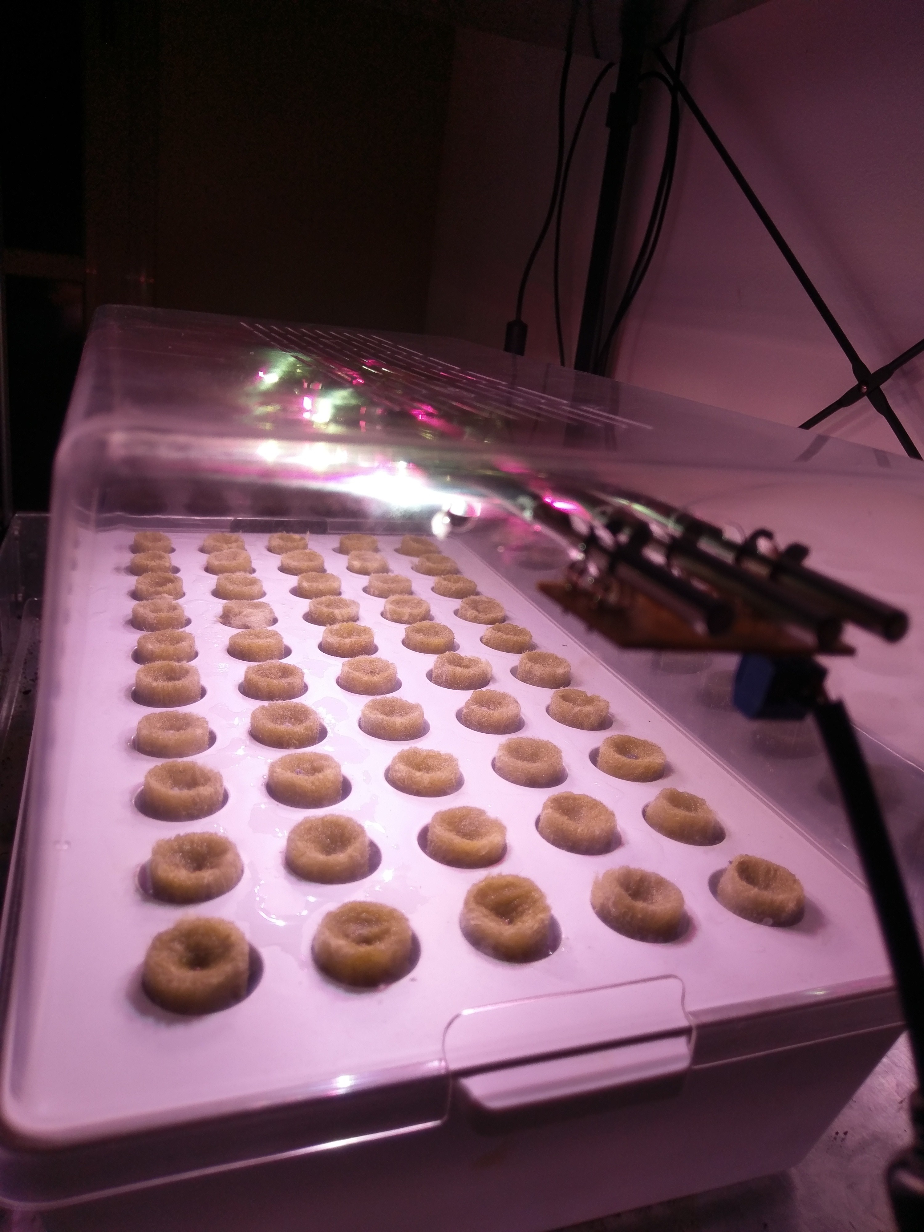
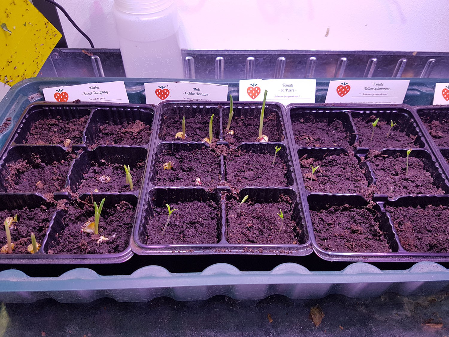
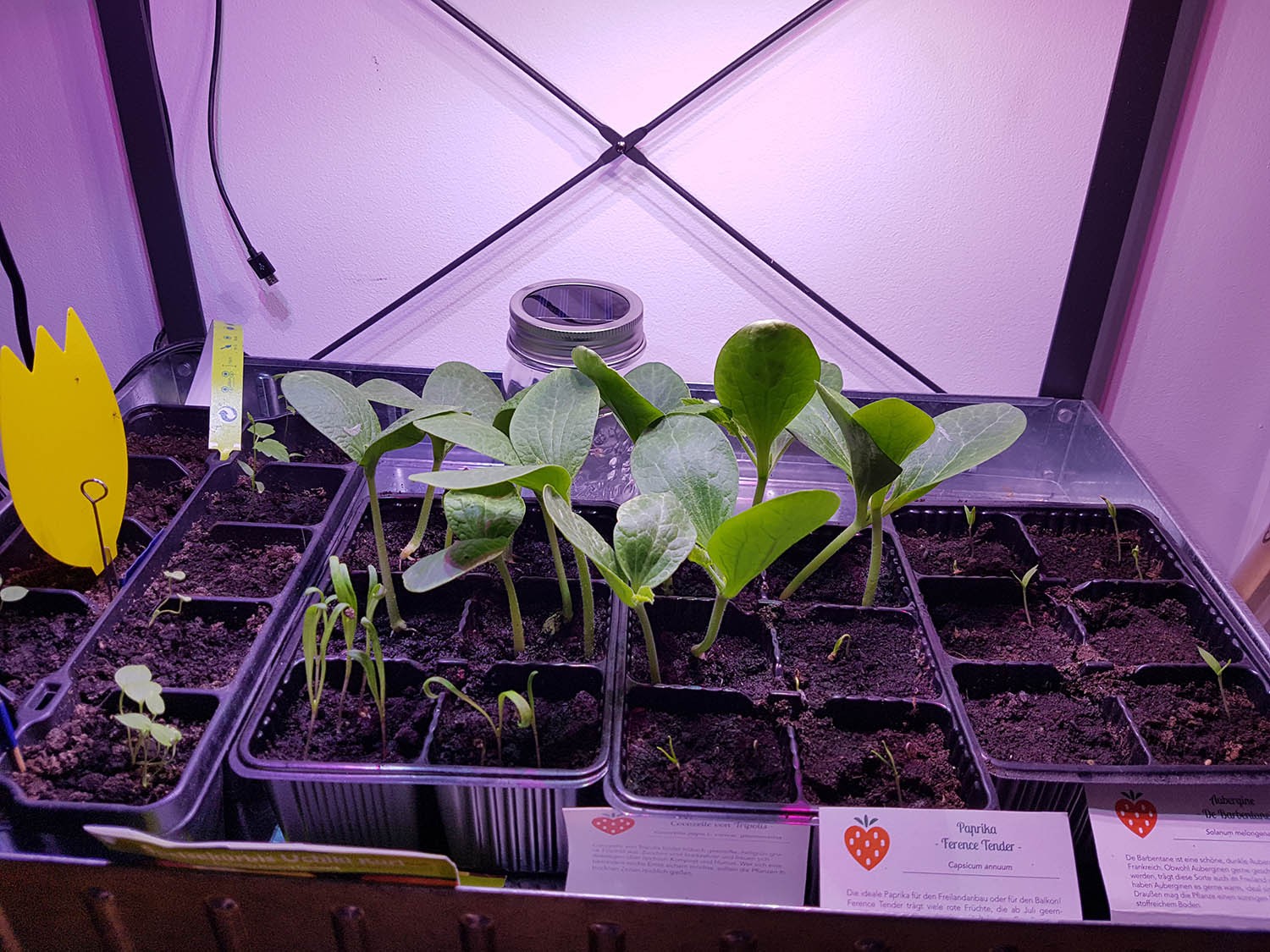
And after a few days:
![]()
-
Final Board Version and some new thermal tests
10/08/2017 at 12:43 • 0 commentsI received my final boards a week ago. I didn't change much, I added an inline resistor to the PWM signal line to limit the current that can flow through the LED driver during a short circuit condition. The VCC line is protected by a Schottky diode but the PWM line was a potential hazard as the ESD protection diodes in the IC would form a direct short through PWM line if two modules were mounted on a rail in reverse orientation to each other. That short can still happen but it wont kill the IC.
The other changes I did were all related to optimizing heat transfer away from the LEDs.
Before the backplane of the module was just one big GND plane. Now it is divided into VCC and GND enabling me to use the VCC metal rod as a heatsink as well. I also increased the amount and density of vias under the LED heatsink pad. I also reflow soldered the LEDs this time, also soldering the heatsink and not just using thermal paste.
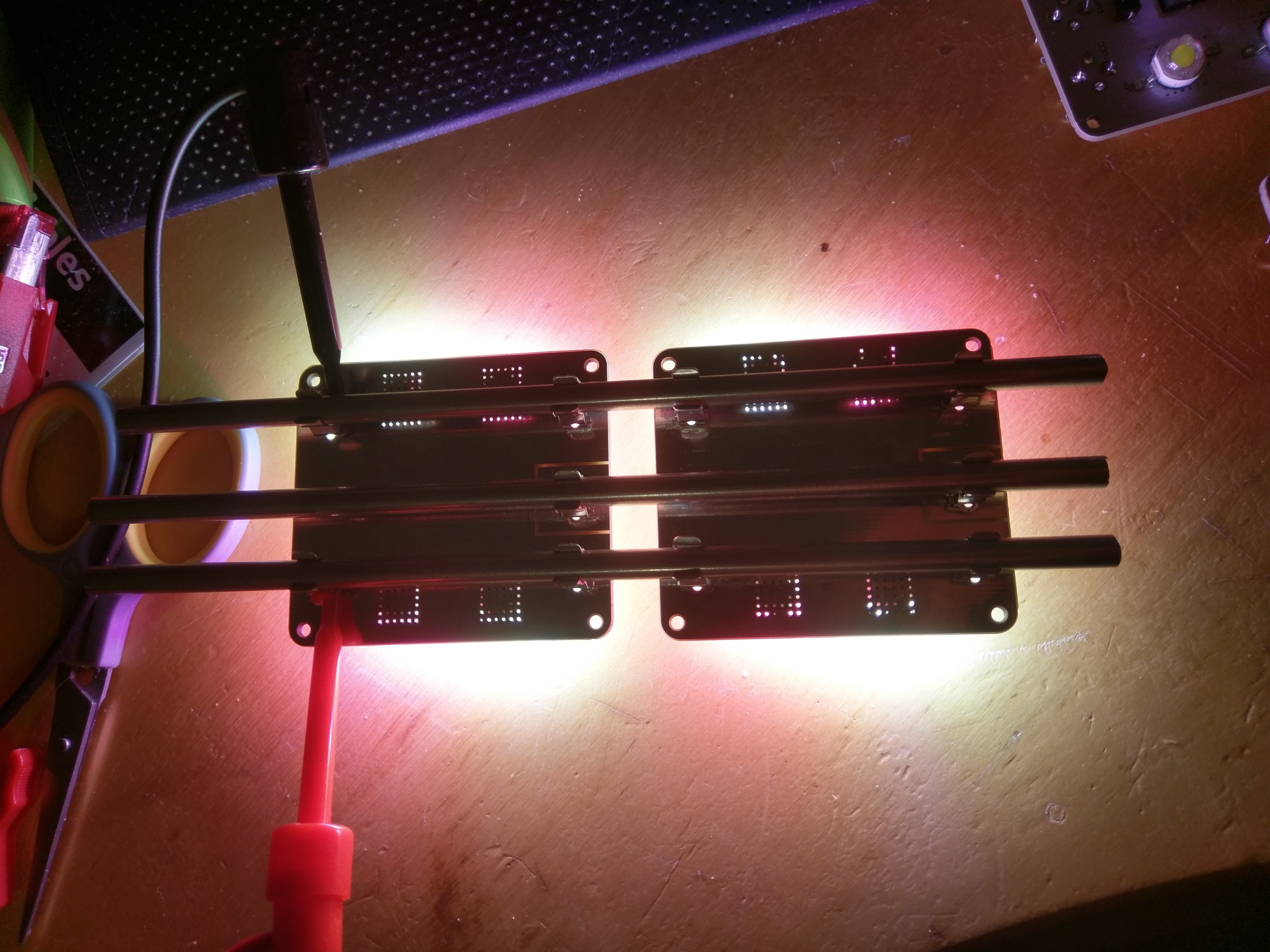
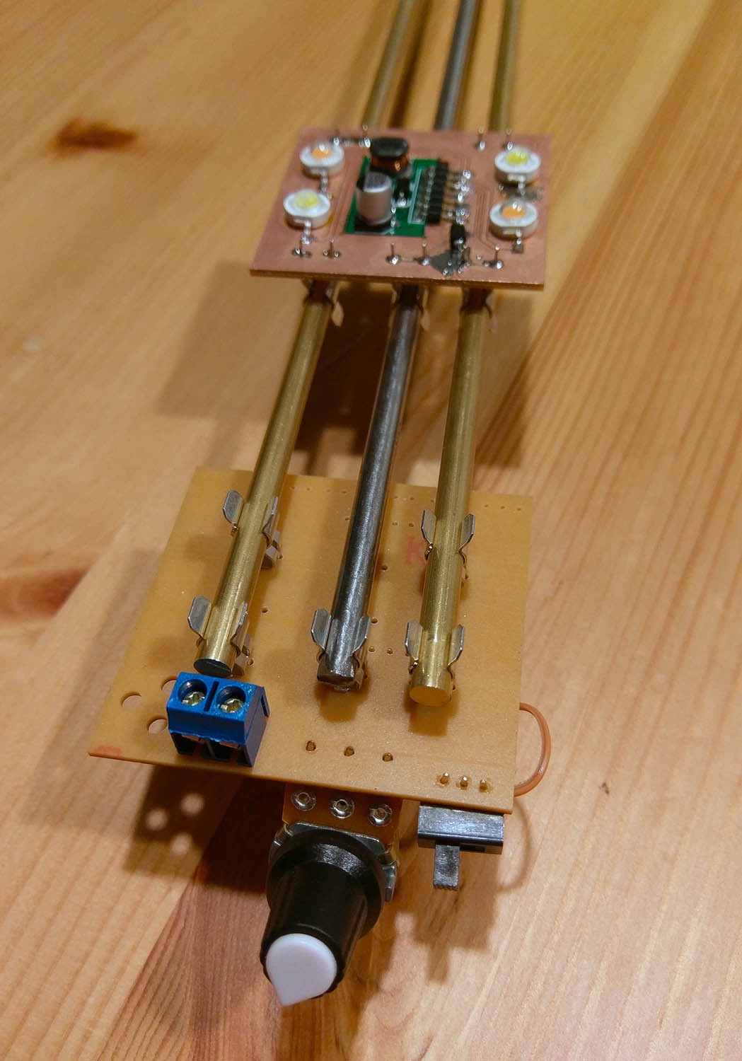
These changes allow for far greater heat transfer and let the LEDs run a lot cooler.Here is my test setup. I attached a K type probe to several measuring points like the junction between rod and fuse holder, the backplane, the front side of the LEDs and the vias directly under the LED heatsink pad:
![]()
I measured a maximum of 54°c at both rods. Before the VCC rod only got to ~30°c and the GND rod to ~43°c. The backside gets a lot less hot with max 83°c measured at the heatsink, before it was around 90°c. At the front the LEDs got to ~70°c+ before the changes, now they only reach about 60°c.
I will make some direct comparison photos with the thermal camera at work.
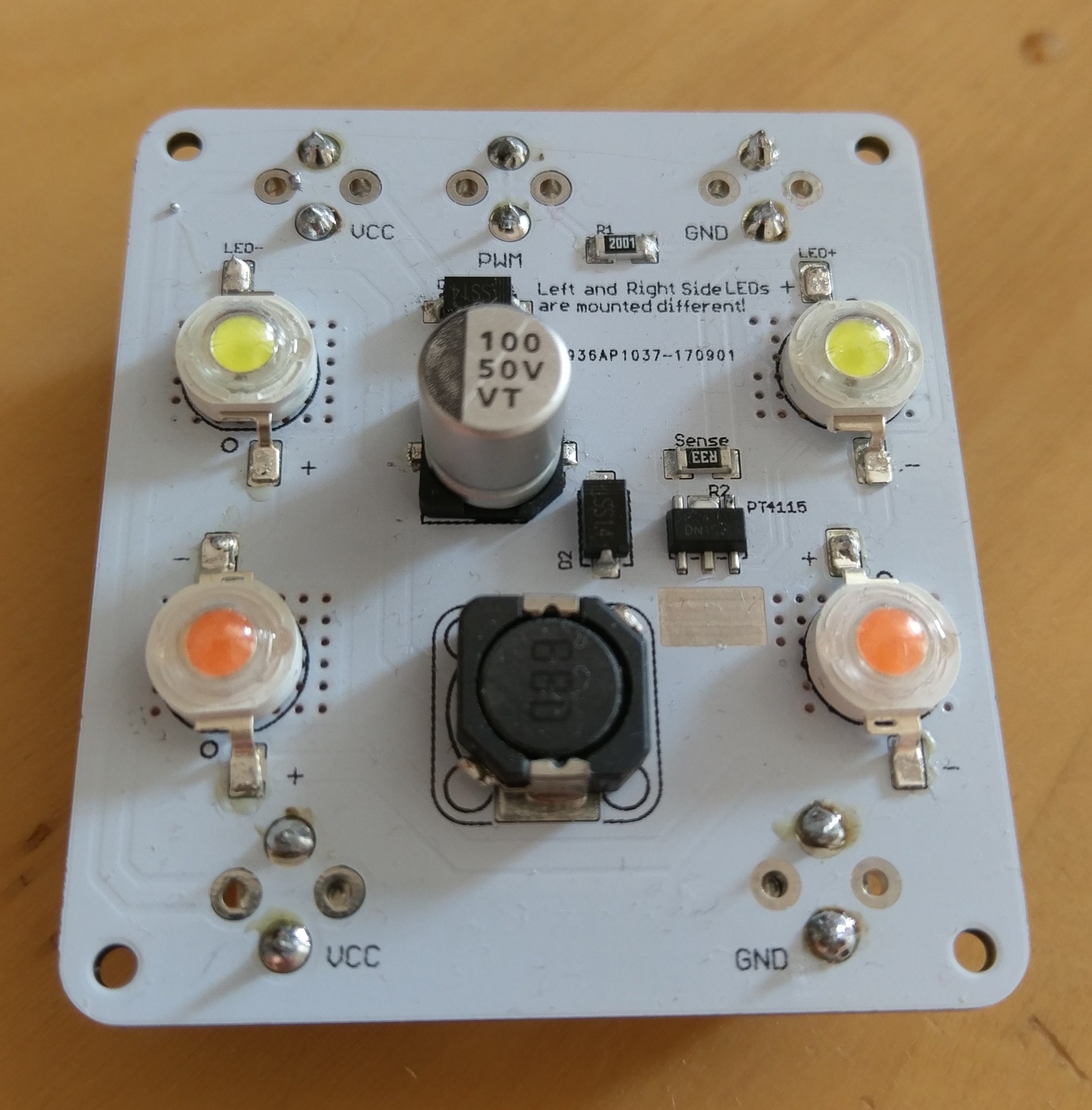
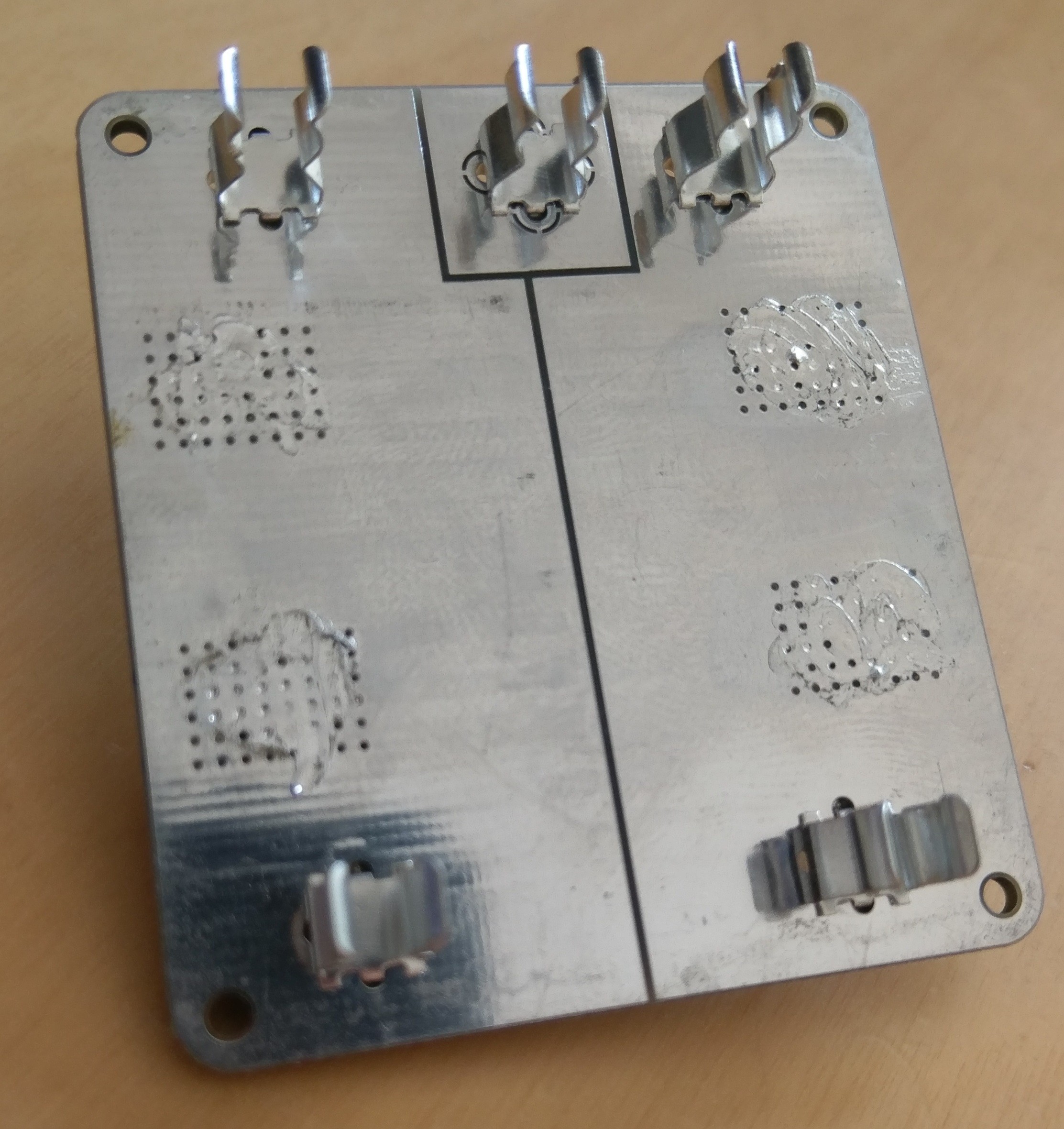
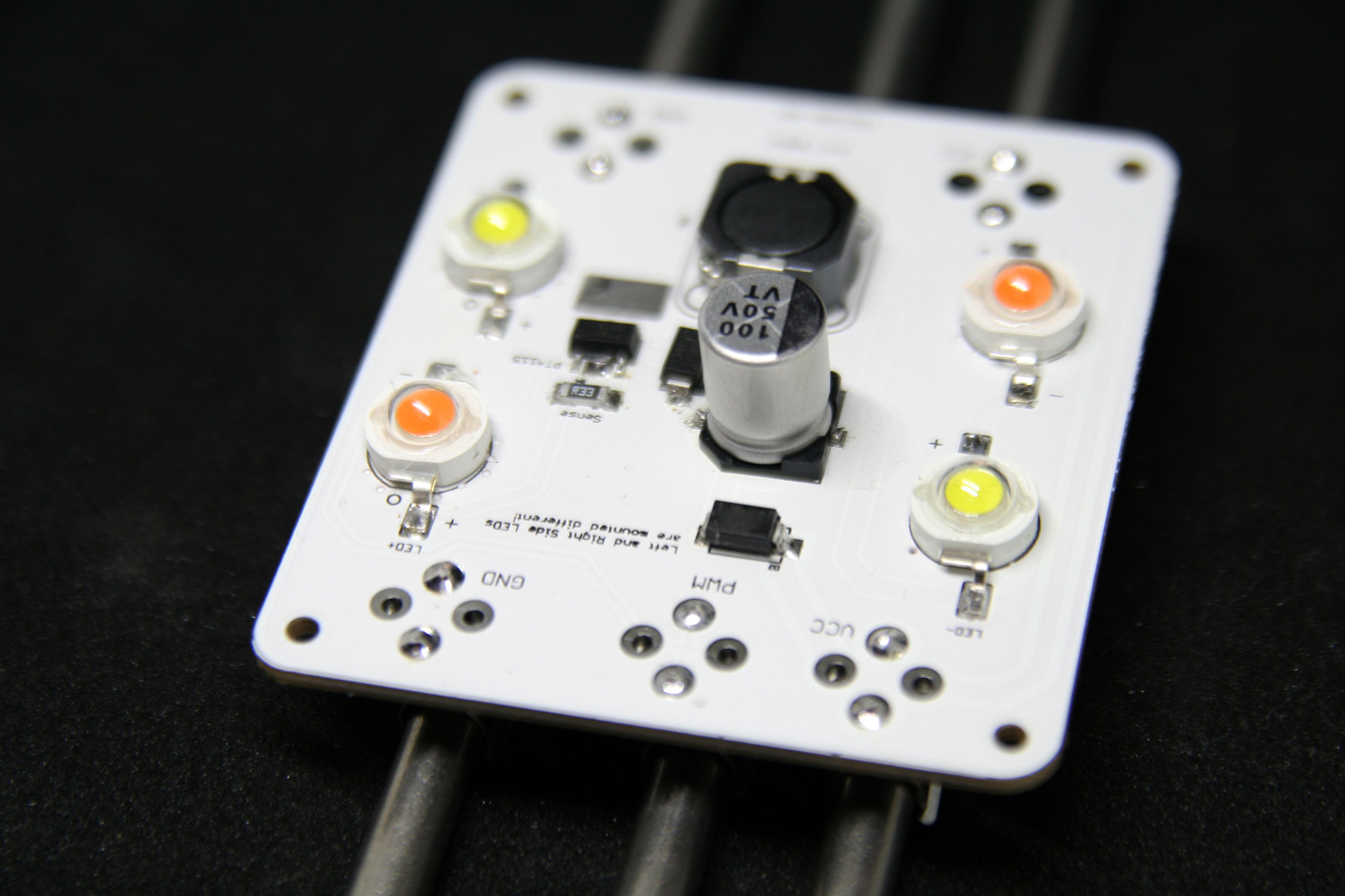
I'm very satisfied with the outcome. At these temperatures the LEDs should have a good life span.And here are two photos of the final board version. Front and back:
![]()
![]()
-
BOM and produced boards
05/25/2017 at 15:54 • 0 commentsI added the BOM for the LED modules to the git repo. For the provided AliExpress shopping links I didn't use the cheapest configuration possible, depending on what type of LEDs you use its a little more expensive than 1.3€ incl. PCBs but also more robust. I will add links for the cheapest config as well.
I also ordered some first PCBs (so far I only tested on milled boards) which came out really nice. Here some picture.
![]()
![]()
Also a few pictures of plant progress:
![]()
![]()
![]()
-
Talking about Automation and Extensibility
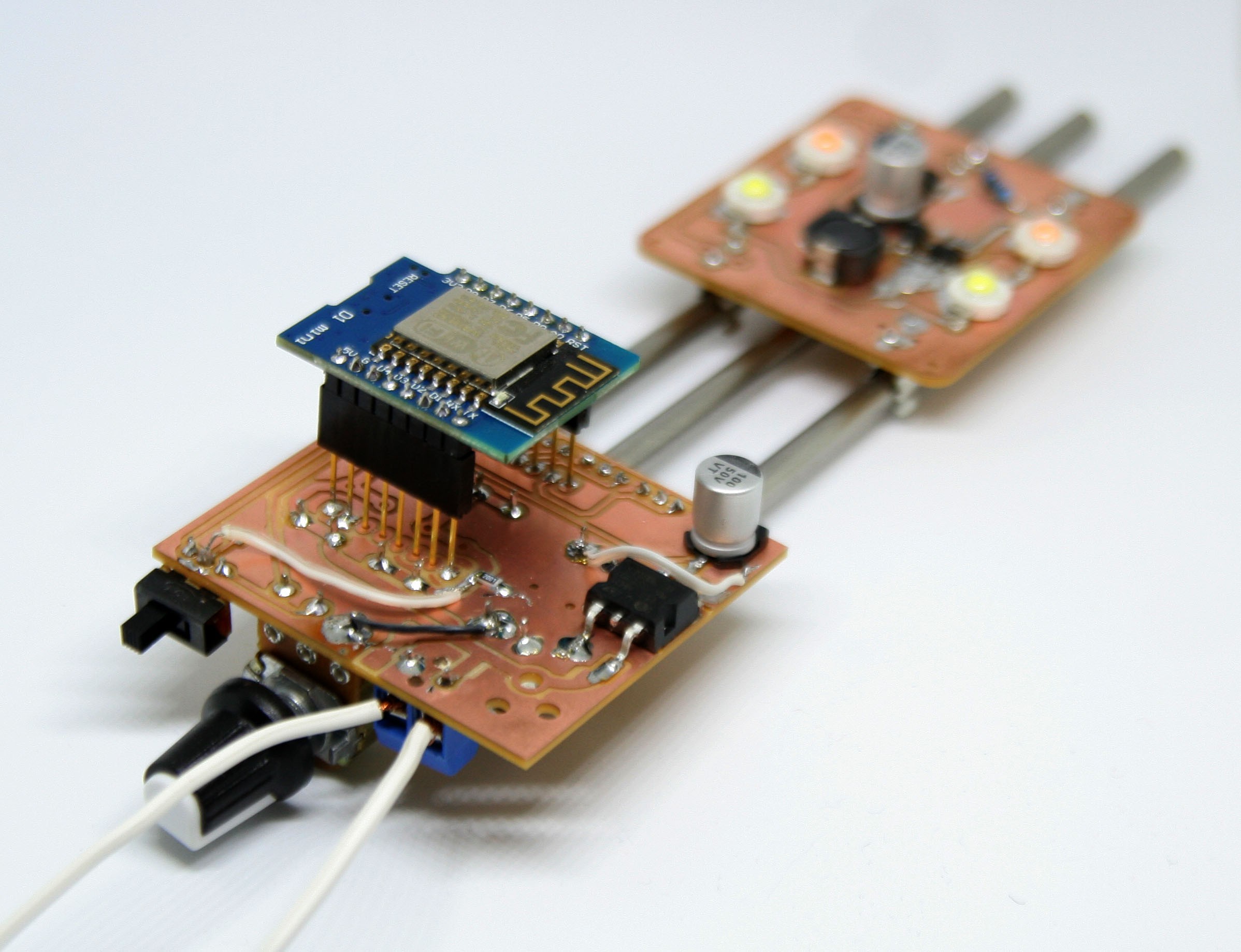
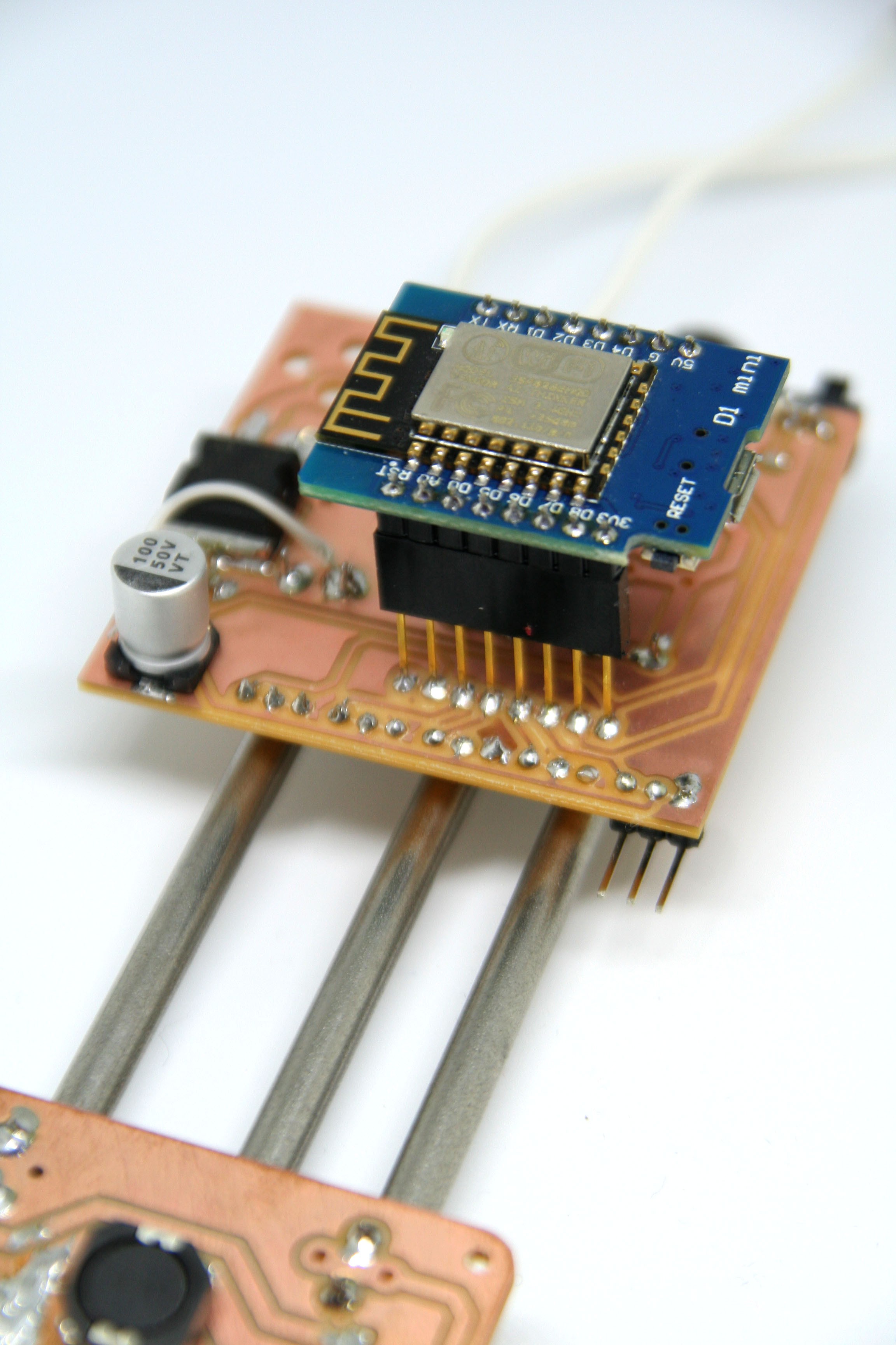
05/14/2017 at 20:52 • 0 commentsI haven't yet talked in detail about the power injection board, which adds the smartness to the project.
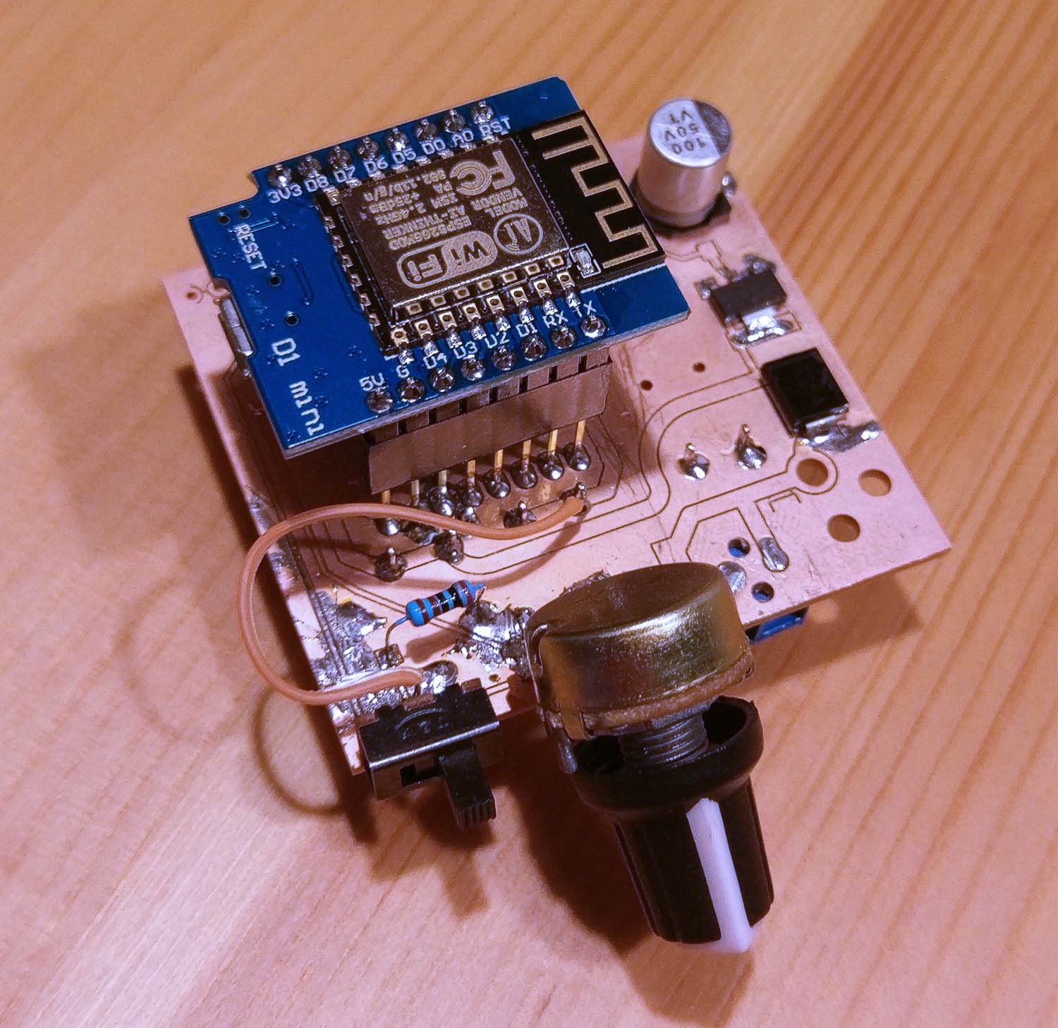
Before I start, here are two photos of the latest version of the prototype:
![]()
![]()
The board
You may wonder why it looks so awkward right now. This is purely a functional prototype, using these long headers for the WeMos D1 makes it easy to solder it to the component side as this is a milled PCB with only a single layer.
So I have to come up with some awkward ways to get this working while having components on both sides. In the final version you would directly solder the WeMos in without any headers to make it as flat as possible (or use headers if you like, thats up to you).
On the second picture you can see a single right angle header mounted. Usually the whole row would consist of 5 of these headers. 4 GPIO headers and 1 ADC header.
Each header also delivers 3v3 and GND. Unfortunately with my milled PCB I have to solder these headers on the bottom where they collide with the metal rods. Normally they mount on the top side. That is also the reason why you only see one header, I had to remove the others when I discovered that it wont fit this way.
I chose the WeMos because it has a fairly small footprint, is available for around 2.3€ from AliExpress/eBay which is not much more than a ESP-12E module and it has a programmer circuit built-in which in my opinion increases usability a lot. All you need for programming is a Micro-USB cable. I didn't see the big benefit of using a plain ESP8266 module other than making the module a bit smaller.
Functionality
So the main reason we have an ESP on there is controlling the brightness of the lamp rail and turning the lamp on and off over WiFi (though that is not all, more on that later). This all happens through the middle rod which carries the PWM signal to all the boards.
If you happen to install the lamp in an accessible place you can also use the potentiometer for manual dimming control. You can switch between both methods using the small sliding switch, left to the pot.I added the potentiometer because I made the experience that its tedious if an appliance is only controllable via a smartphone or a computer. Sometimes you are just walking by and want to turn it off for the moment or dim it down a little, without accessing another device first.
For the ESP I have a very specific workflow in mind, that is supposed to make things very easy in terms of customizing behaviour and extending the system beyond of what its offering.
The central part here is node-red. For those of you who never heard of node-red. Its basically a Javascript based visual flow programming tool with a web based UI that runs on any platform. Read more about it here: https://nodered.org/
Node-red is really powerful if you simply want to define behaviour using complex inputs and outputs like a calender for example but don't want to actually have very complex logic in between the two and mostly just route between these inputs and outputs. In order to utilize the power of node-red the firmware for the ESP will use MQTT and break out the PWM output to a MQTT topic. So you can just send a bunch of numbers to the PWM pin and that's all you need in order to dim or turn on/off your lamp.
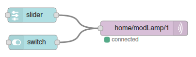
Not only the PWM pin will be broken out over MQTT, the GPIO pins and the ADC will also be broken out as a MQTT topic. So this enables you to define behaviour for the ESP without re-programming it physically. That way you can do some really complex stuff within seconds. Here is a video showing a mobile UI with a slider for dimming and a toggle button that switches between off and 20% on. Unfortunately the slider only updates when touch ends which makes this a bit sloppy looking but in theory you can have really smooth fades.And all it need to get this functionality was adding the dashboard addon to node-red and this flow:
![]()
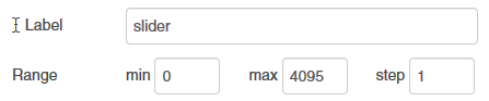
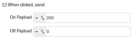
Dead easy. All I defined within the switch and slider node was what numbers they should output.
Slider:
![]()
Switch:
![]()
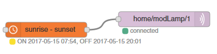
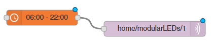
If you want automated control like f.e. having the lights follow the natural rise and dawn of the sun or turn on and off at a specific time everyday. You can simply do this:
![]()
![]()
That are just some examples for defining behaviour for the lights. It starts to get really powerful if you think about the fact that you also have IOs and an ADC, accessible in the same way. Lets go through an example.
Maybe you want to include a simple warning for when your plants need watering. You get yourself one of these really cheap sensors that you can just stick into your plant medium or maybe a photo interrupt sensor to detect if a floater goes below a specific threshold.
You attach the sensor to one of the headers, no need to run extra power as you get it from the header.
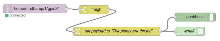
You go into node-red and setup a flow the other way around, listening to an MQTT topic instead of writing to one (in the case of GPIOs you will be able to configure them as in our output over a persistent configuration topic). You then determine what should happen when you read a specific value on that topic. Maybe you want to be notified via e-mail or push notifications through a service like Pushbullet.
This simple flow will do this for you:![]()
You can easily push this further and instead of notifying yourself you can make a closed loop watering system that depending on the sensor status write to another GPIO which controls a water valve, watering your plants. As soon as the sensor reads that there is enough water again, the valve will be closed. It can be as easy as:
![]()
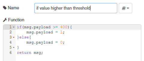
Node-red is always evaluating, so this is not a one shot thing but more like an infinite while loop, reading the ADC value over MQTT, checking if a threshold is reached and if it is, sending a 1 and if not a 0.
This is using a very powerful feature of node-red, which is that you can write small code snippets in Javascript to extend node-reds functionality on the fly. It reads the adc value and changes the payload variable to a binary value that the GPIO can understand.
![]()
You can see how by combining the right technologies, a simple hardware system like this can become very powerful and extendible without being complicated.
Extending the hardware
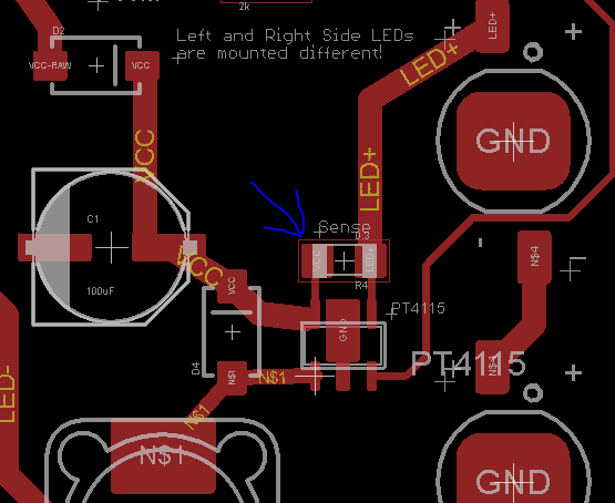
In terms of extending the functionality of the modules themselves you also have more than a few possibilities. You want to use a single 10W LED instead of 4 1W LEDs? No problem, the only thing you need to change in the circuit is this resistor determining the constant current limit for your LEDs.
![]()
By default it is set to be a 0.3 Ohm resistor. Setting the current to 0.1/0.3 = 0.333A.
Maybe you want addressable LEDs on a 3m long track? Just add a small microcontroller to the board like the ATtiny85 and some solder pads to set an address for each module. Now you can have addressable communication over the middle rod (lets call it signal rod) instead of a PWM signal.
No matter where you place a module on the rod, it will always be configured the same. Maybe you have one set of modules configured for warm white dimmed to a certain brightness and the rest to be cold white, also dimmed to a certain brightness.
Now you can go ahead and place modules on your long rail and mix the two colors by sliding modules and placing them in different positions, creating different lighting conditions as you please and being able to tweak them in software all at once. Or have a different address for every module and go crazy in node-red.
Maybe you don't want a lamp at all in there but modules with a small speaker utilizing the rail system for power and using the signal rod for volume control. Maybe mix lamp modules and sound modules and set the volume of your music according to the brightness of your lighting, if that's something you desire...
The point is that you are not limited to having LED modules, the system can be used for pretty much anything else that needs power, a fixture and some way of communication.
-
Some plant growth
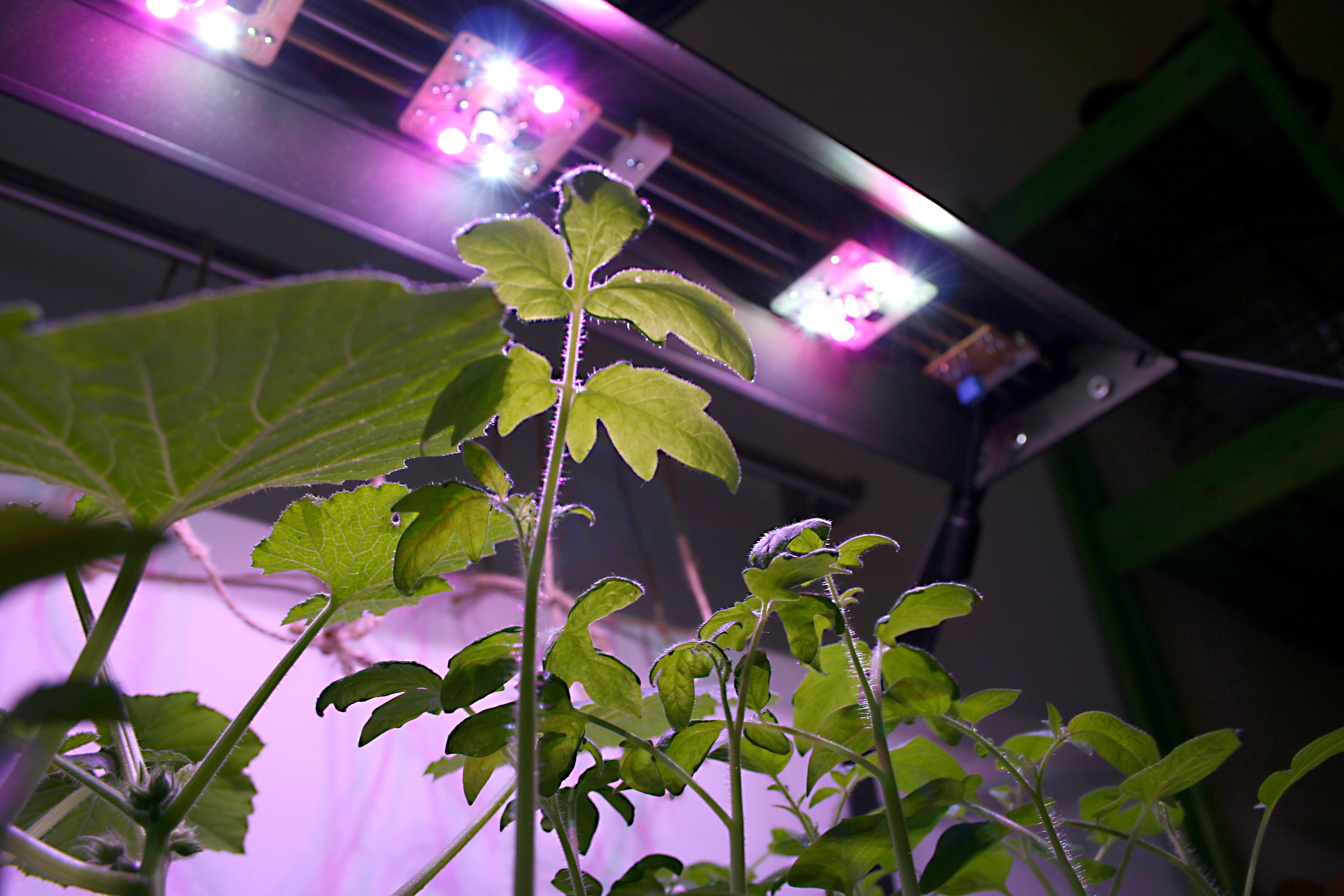
05/01/2017 at 14:07 • 0 commentsI planted a few seed last week and put them under 2x3 modules. I also put a batch that I planted a month ago under the lights as well. The results are tremendous. The month old seedlings were pretty slow growers and rather weak, one seedling came fresh out of the earth shortly before I put it under the light modules and it outgrew its brother that came out 2 weeks earlier in a matter of 5 days.
Here some pictures. The first 2 are made after 6 days of planting the seeds (or 4 days after they actually started germinating). The last two are made 2 days after the first 2 images.
After 6 days![]()
![]()
After 8 days:
![]()
![]()
Update after 11 days:![]()
![]()
-
Some 3D prints and first test with the IKEA system
04/14/2017 at 18:50 • 0 commentsI printed some of Max fixtures and altered them a little so they can fit the mounting holes on the IKEA system. In the end there will likely be a ton of different fixture combos that cover all kinds of situations.
I think the picture speak for themself. The fixtures are really nice you can snap the lower part onto the rails and then slide in the top part from the side.
The prints are not of the best quality but they work perfectly mechanical wise.
I will add some photos later when I actually mounted the whole thing on the IKEA beds.This one uses a slightly modified top part, instead of the hole for the nut it has a 11mm hole that fits the little mounting hole thing on the ikea hydropnic beds ( compact: http://www.ikea.com/de/de/catalog/products/90319065/ bigger one: http://www.ikea.com/de/de/catalog/products/00319003/). If you zoom into the compact light fixture I linked you can see in the top right corner the mounting hole I'm talking about.
![]()
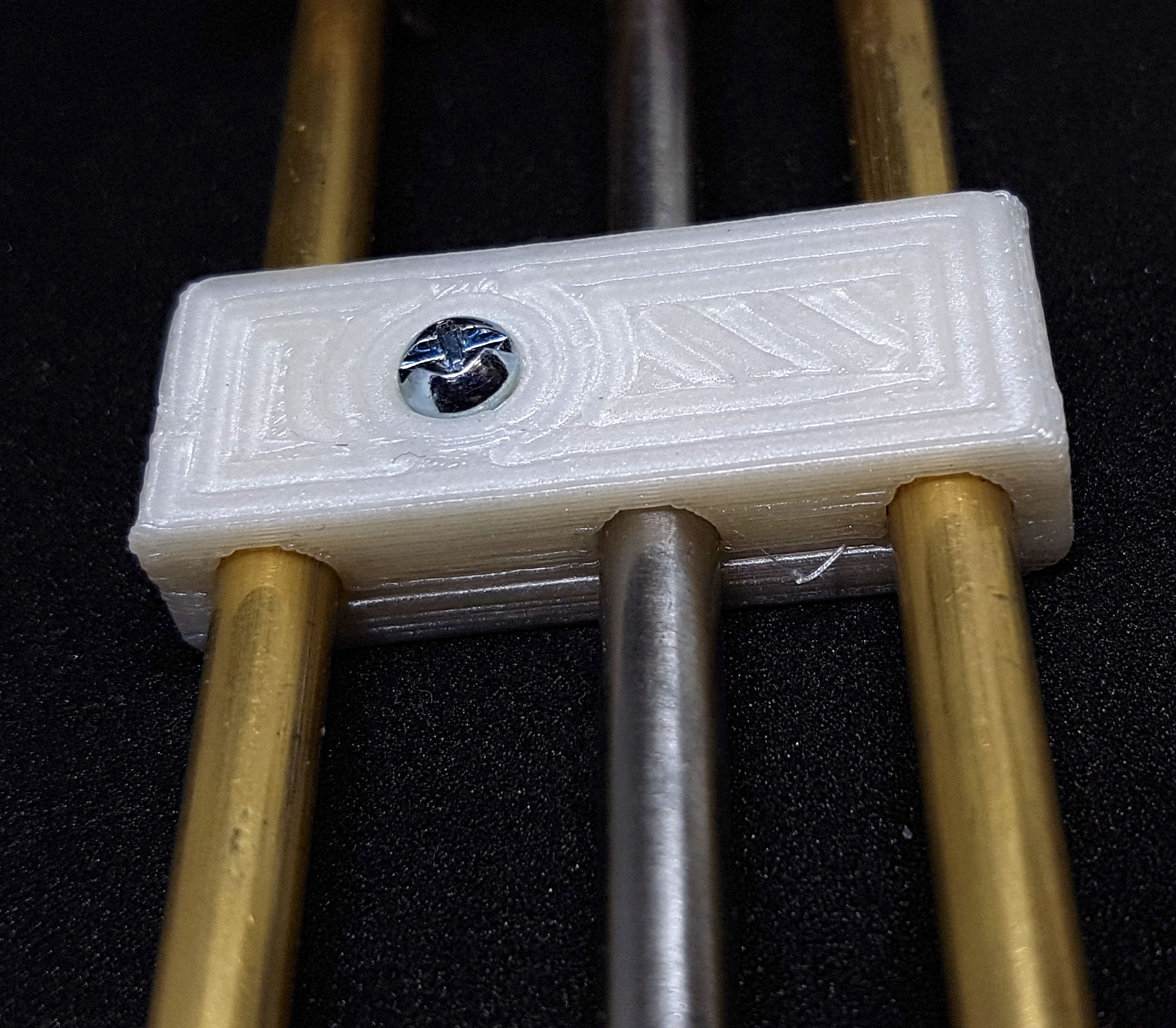
This is the normal middle one. I didn't use countersunk screws as I didnt have any but normally you would use a countersunk one.
![]()
-
Mechanical parts
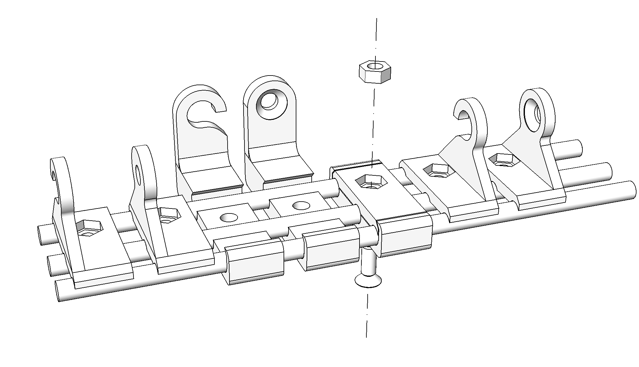
04/03/2017 at 22:42 • 0 commentsAn update for the 3d printable holder clips: There are now different options to mount the rails either against a rear wall, against a ceiling or between two walls.
check the picture. File names are self-explanatory.
Now uses M4 countersunk screws for better compatibility. Needs M4x10mm ideally.
To mount against a ceiling, just replace the M4 screw with a wood screw for example.
These print fine on an Ultimaker 2.
![]()
-
Heat issues
04/01/2017 at 23:07 • 3 commentsPreviously I ran the 3W LED Quartets at about half the maximum current, heat dissipation worked fine with some big exposed pads on the PCB. With the new modules I wanted to run them at their full specified current of 700mA but that turned out to be a thermal nightmare. I would have to add a huge heatsink to the LEDs in order to keep them at around 50°c.
So I have two options, stick with 3W LEDs and limit the current to 400-500mA or go with 1W LED chips.
Considering a low price point while still being a very usable thing is my main selling point for this project I will probably switch my design to 1W LEDs and do some testing if I can get a way with exposed pads on the back side of the PCB. If not I'm thinking about attaching some thin copper shims to the back, you can get them for around 17 cents for a 20x20x1mm one (at qty 50, see the link below). -
Power Injection Prototype
03/27/2017 at 00:24 • 1 commentI soldered up a prototype for the power injection/dimming module. It looks a bit weird but seems to be working so far, the potentiometer glitches a little in certain positions. Which may come from the fact that I accidentally wired it up the wrong way. While the diode should prevent damage, something started smoking, will have to investigate why that happened.
But power delivery was working fine for a single module at 16V 0.7A.
Some photos:![]()
Normally the ESP wouldn't be on these stacking headers of course, I just used these so I could solder them on the component side as this is a single layer PCB.
Mounted:
![Mounted]()
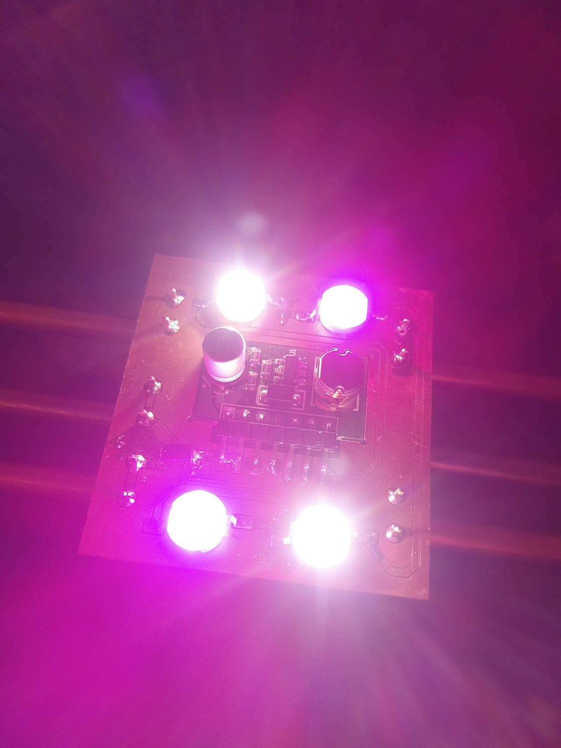
Module powered up, dimmed down to ~30%:
![]()
MoRaLiS: Modular Rail Lighting System
A very affordable lighting system that can be used as efficient grow lights for indoor plants and customizable ambient lighting.