CNC Mill Conversion (RF30)
Makerspace Newcastle has an elderly, worn out RongFu RF30-clone mill. Let's freshen it up and CNC it :-)
Makerspace Newcastle has an elderly, worn out RongFu RF30-clone mill. Let's freshen it up and CNC it :-)
To make the experience fit your profile, pick a username and tell us what interests you.
We found and based on your interests.
XAxis_FFMount.fcstdFreecad file for the FF15 mounting plate for the LEFT hand side of the X axisx-extension-fcstd - 11.49 kB - 04/22/2017 at 18:49 |
|
'm currently working on plans for CNC conversion of the X-Axis and installation of a ballscrew and ballnut.
Like the Y Axis, I plan to use a 20mm 5mm pitch ballscrew.
At the moment, I don't have the ability to machine things very accurately (existing X axis backlash is horrendous!), I am using flanged ballscrew supports (FK15 and FF15) and paying the supplier of the ballscrews to turn them down and thread them to fit the flanges.
The flanges for mounting the ballscrews look like this:
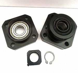
The FK flange has a securing nut to tightly grip the ballscrew so it can rotate, but not move backwards or forwards. The FF flange simply supports the ballscrew but doesn't stop it moving backwards or forwards. The reason it isn't tightly secured at both ends is to account for change in its' length due to thermal expansion.
For the X axis, as you look at the machine, I am going to fit the FF15 leadscrew support on the LEFT hand side of the X axis table, and the FK15 and stepper motor mounting onto the RIGHT side.
For the FF15 bearing mount, I have designed the following plate (which I am machining out of 3" x 1/2" thick Alu bar):
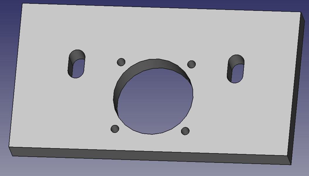
This has a centre hole and four M4 drill holes (which I will tap out to M5) to take the FF15 flange. The two slots are for mounting to the X axis table using the existing mounting bolts and will allow some adjustment in the vertical position of the plate.
This mounting is a bit more complicated, and consists of FOUR pieces of milled aluminium bolted together.
Firstly, a plate similar to the FF one, which bolts to the mill table using the existing bolts: This one is slightly thicker, and is made of 3" x 3/4" thick bar.
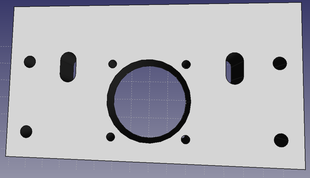
Main differences here are:
Thicker plate (15mm) as the FK15 bearing mount is thicker and it needs to be contained within the plate ideally.
Four additional holes (countersunk at the rear of the plate) to take M6 allen head bolts to bolt the spacer plates on, which will then themselves secure to the motor mount)
The spacer plates are 60mm 'high', 10mm thick and the appropriate length to accommodate the shaft of the ballscrew, the flexible coupling, and the stepper shaft.
They are tapped to take M6 bolts to attach them to the FK15 mount plate shown above.
CAD files and exact length specifications pending!
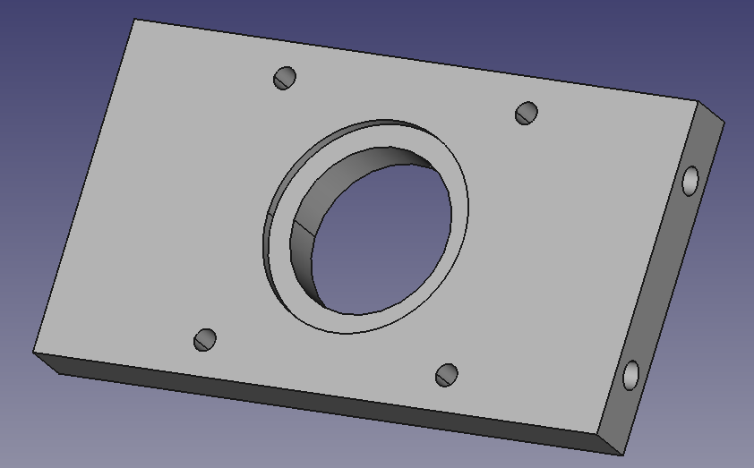
This plate bolts to the two spacer plates and completes the FK15 and stepper mount assembly. The stepper motors I am using are NEMA24, so the hole spacing etc is made to suit it.
This plate is also machined from 3" x 1/2"thick Alu barstock. It has a mounting hole for the stepper motor shaft to protrude through, a bored out 'lip' that the stepper motor centering 'lip' sits into, as well as four tapped holes for the M5 mounting bolts to hold the stepper in place:
Once I've machined and assembled these, I will post photos which will make things a bit clearer!
I've had a few days at home on and off to work on assembling the main stepper motor driver hardware.
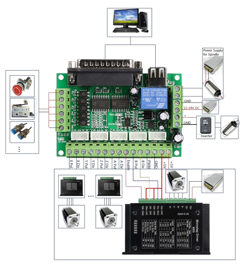
The basic architecture is based around a 36VDC PSU, 3 M542T stepper motor controllers, and a opto-isolated parallel port interface board.
I found these all fitted very nicely into a small PC case I purchased from Amazon, as seen below:
(wiring still needs to be neatened up with some wire-ties, as well as making a small panel to mount the 4 pin connectors to plug the steppers in). For connectors, I am going to use 4 pin 'aviation' connectors, which are screw-in, thus reducing the risk of motor disconnections which can damage the drivers.
I have also added a small DC-DC converter to produce a 12V supply from the 36VDC PSU. This means I can drive the original case fan to improve airflow over the drivers.
The wiring diagram showing how to wire the parallel port interface card is here:
(Note the stupid design of having a USB 'A' SOCKET for 5v power *IN* from the PC. They've supplied a USB 'A' to USB 'A' lead for this purpose. <shrug>)
Also, the 12-24VDC supply shown on the right is optional and only needed if you are using a 0-10V output signal for the inverter. I'm not.
For the Y axis mounting for the ballscrew, I decided to use a FK15 standard flanged ballscrew mount.
I chose to drill 6 M5 holes (to tap to M6) in the front of the mill casting to support an aluminium plate with an FK15 cutout (to make later!)
Because our Makerspace had a laser cutter, I created a DXF file to use as a drill template, and laser cut it out of 3mm ply wood. You could equally print it out and stick it on, or mark the holes by hand (carefully)
The 6 outer holes need to be drilled to M5, and then carefully tapped out to M6. Because the base of the mill is cast iron, no lubrication is required to drill or tap, as the carbon in the cast iron provides this. I used the M7 bolts that had held the original Y axis leadscrew mounts to hold this plate on to ensure the holes were in the right place.
Here's a photo with my laser cut ply drill guide bolted to the front of the mill prior to drilling of the holes.
The DXF file (and the freecad file used to generate it) is in the Projects file section. Note: The file doesn't include the centre holes for the FK15 ballscrew mount (the large centre, and the four surrounding ones) so just has the two holes for the existing bolts, and the 6 edge ones for the new mounting bolts.
Components Needed
I will explain a little about the options I considered for each, and what design decision I reached for each one.
Makerspace has an RF30-clone mill (these are originally made by a Taiwanese manufacturer called Rong Fu), and rebadged and resold by a large number of third parties. This was very kindly donated by one of our members, Ben Shaw.
Ours is name-plated as the "MSC Industrial Supply Company" but there are a number of other resellers, including Axminster, in the UK.
Because of this, there are often incompatibilities between the machines, as each manufacturer has made customisations to their models.
It is a ROUND COLUMN mill - this means that you can adjust the height of the mill by undoing two bolts and turning the height adjust handle. But because it is a round column design, the quill will lose its' alignment in X and Y, as well as changing height. This is a bit of a disadvantage, but is not trivially easy to rectify.
Drive system
It is powered by the original single phase 240VAC 1.5HP motor, and has a belt and pulley arrangement to allow a variety of drive speeds.
The machine axes are as follows:
Y axis. Located most inferiorly on the machine. The lead-screw is left hand thread, and drives a brass casting with the lead-thread cut in it. This moves the Y axis along the machine's slides (front to back)
X axis - acme lead screw, brass lead-nut is bolted to the centre of the Y-axis table, the lead screw is anchored at both ends, and by turning the screw the table moves (left to right)
Z axis - coarse adjust, and a lockable fine-adjust with a worm gear driven by a Z axis handle.
Current issues
We can address points 1 and 2 by a CNC conversion , involving replacing the leadscrews with a nice modern ballscrew and ball-nut, and stepper motor drive.
Point 3 is something we will just have to live with!
Create an account to leave a comment. Already have an account? Log In.
Hi,
I have cncd x and y so far and am using it to remake the parts as shown above to improve their accuracy.
I will try and post some video shortly.
Cheers
David
Become a member to follow this project and never miss any updates
Nice write up. Did this project come to fruition? I want to convert mine to CNC and start buying the parts necessary. Ive seen a few directions people have gone with different stepper/servos and controllers from Mach to Fastcutcnc. Id like to see a youtube video running and over view of the completed project if you have a link. Thnks.