I've had a few days at home on and off to work on assembling the main stepper motor driver hardware.
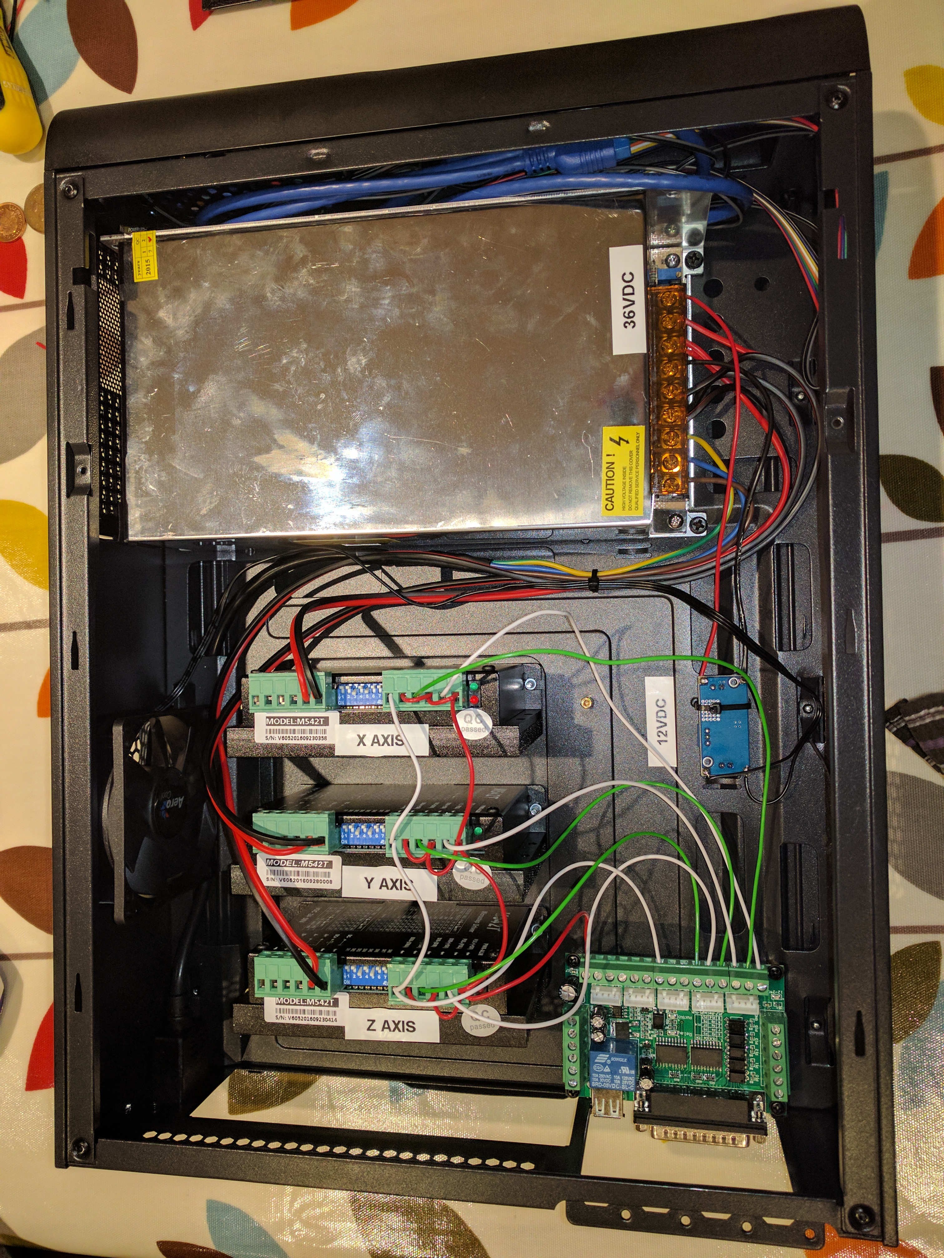
The basic architecture is based around a 36VDC PSU, 3 M542T stepper motor controllers, and a opto-isolated parallel port interface board.
I found these all fitted very nicely into a small PC case I purchased from Amazon, as seen below:
(wiring still needs to be neatened up with some wire-ties, as well as making a small panel to mount the 4 pin connectors to plug the steppers in). For connectors, I am going to use 4 pin 'aviation' connectors, which are screw-in, thus reducing the risk of motor disconnections which can damage the drivers.
I have also added a small DC-DC converter to produce a 12V supply from the 36VDC PSU. This means I can drive the original case fan to improve airflow over the drivers.

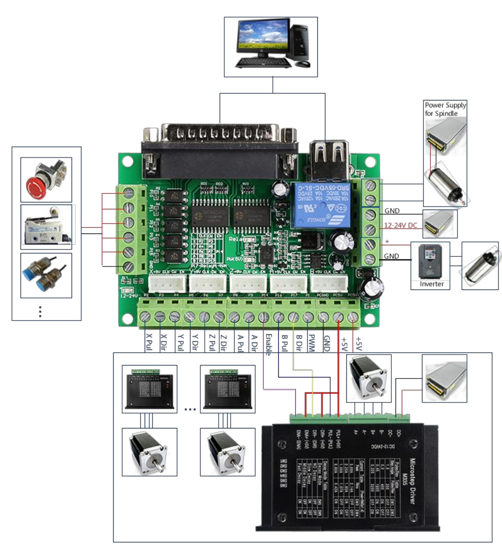
The wiring diagram showing how to wire the parallel port interface card is here:
(Note the stupid design of having a USB 'A' SOCKET for 5v power *IN* from the PC. They've supplied a USB 'A' to USB 'A' lead for this purpose. <shrug>)
Also, the 12-24VDC supply shown on the right is optional and only needed if you are using a 0-10V output signal for the inverter. I'm not.

 David Pye
Discussions
Become a Hackaday.io Member
Create an account to leave a comment. Already have an account? Log In.