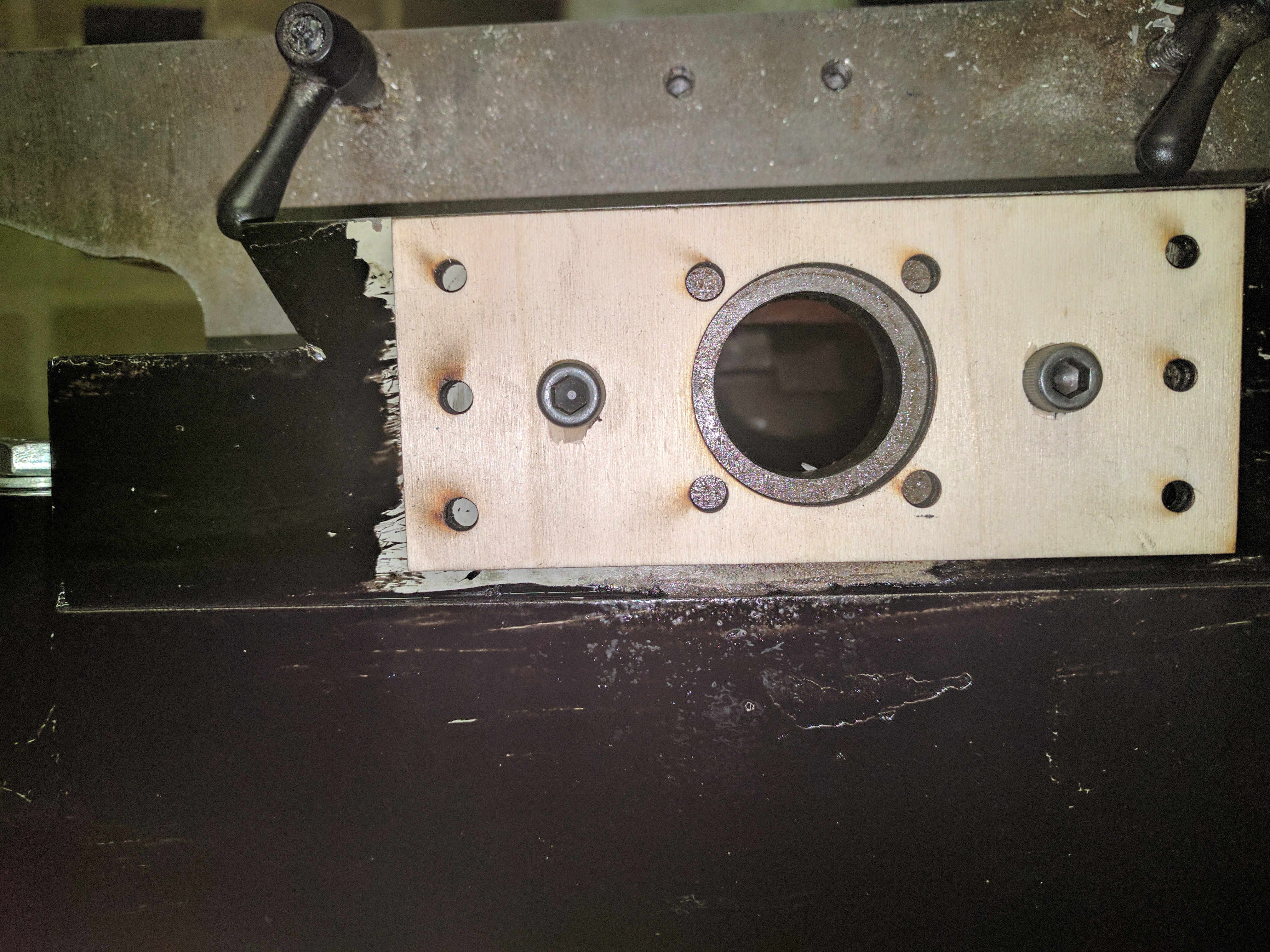
For the Y axis mounting for the ballscrew, I decided to use a FK15 standard flanged ballscrew mount.
I chose to drill 6 M5 holes (to tap to M6) in the front of the mill casting to support an aluminium plate with an FK15 cutout (to make later!)
Because our Makerspace had a laser cutter, I created a DXF file to use as a drill template, and laser cut it out of 3mm ply wood. You could equally print it out and stick it on, or mark the holes by hand (carefully)
The 6 outer holes need to be drilled to M5, and then carefully tapped out to M6. Because the base of the mill is cast iron, no lubrication is required to drill or tap, as the carbon in the cast iron provides this. I used the M7 bolts that had held the original Y axis leadscrew mounts to hold this plate on to ensure the holes were in the right place.
Here's a photo with my laser cut ply drill guide bolted to the front of the mill prior to drilling of the holes.

The DXF file (and the freecad file used to generate it) is in the Projects file section. Note: The file doesn't include the centre holes for the FK15 ballscrew mount (the large centre, and the four surrounding ones) so just has the two holes for the existing bolts, and the 6 edge ones for the new mounting bolts.
 David Pye
Discussions
Become a Hackaday.io Member
Create an account to leave a comment. Already have an account? Log In.