 M. Ż.
M. Ż.A bit of history first.
The Opus is a grinder made by Fellow, an American company specializing in good-looking, well-working coffee brewing gear. Grinders, electric kettles, mugs, and lately even espresso machines. I bought my 2023 model in 2025 and I was very happy with it, even if for that price (700 PLN, so around 200 USD) I’d expected a bit more.
It served faithfully for a year and then, for no obvious reason, stopped working properly. It behaved as if the motor were choking, losing power. The internet pointed at capacitor problems and certain design shortcomings. My unit was still under warranty, so I decided to make use of that. Somewhat to my surprise, Fellow’s Polish distributor didn’t ask me to send the faulty unit back for repair - they just shipped a new one straight away (the 2025 model, in which you can spot a few subtle changes and fixes). The broken grinder went on a shelf for a few months. What kept me going was the thought: “if it’s only the capacitors, I’ll be able to fix it and have two grinders - profit!”. I was just getting into electronics at the time, so it sounded like an interesting project.
Eventually the thought ripened enough and I got down to taking it apart. Sadly I didn’t photograph the whole process, but the few shots I did take are here.
Teardown
First observation, the moment I started: this thing is wonderfully serviceable! No snap-fits that break off, no housings you have to pry open while risking damage. No hot glue, no components drowned in some strange goo. All you need is a screwdriver (Philips, size 2) and tweezers (bent ones, to make life easier). No instructions, no googling “how to disassemble…”. The further I got into my old grinder, the bigger a Fellow fan I became. So it can be done right, I thought. At the same time I grew increasingly puzzled that the warranty claim got me a new grinder instead of a repair of this one. Business processes are strange, but thanks to that we now have this write-up.
Once all the layers of housing were off (the grinder is Class II per IEC/EN 61140, so the enclosure itself does the protecting and the appliance needs no earth conductor - which is why there were quite a lot of those layers), I found myself looking at the PCBs - modular as well, joined by pin headers, with wires neatly landed in faston terminals. One labeled power board, the other control board.
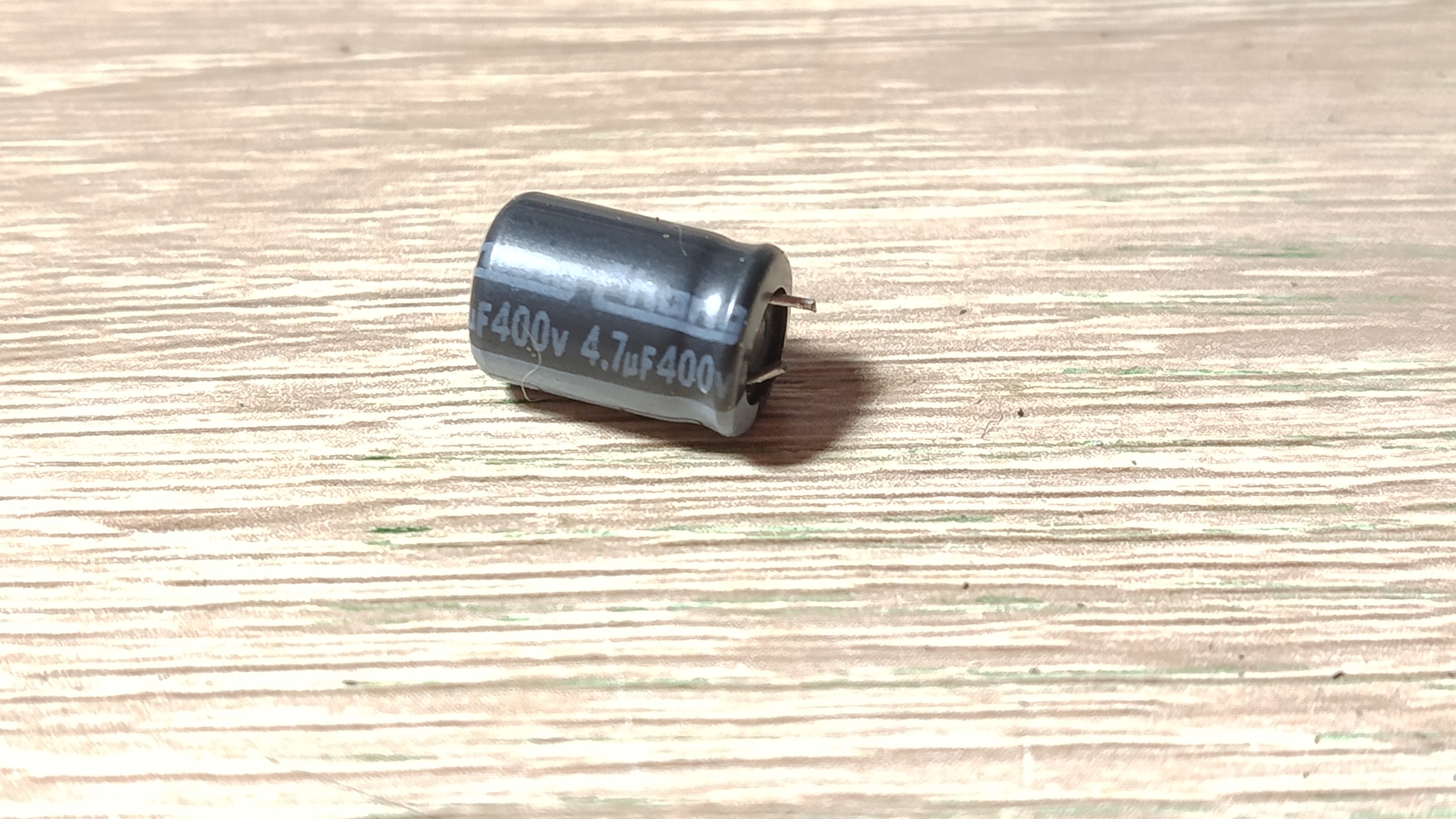
I identified the cause of the failure quickly - two THT electrolytic capacitors (4.7 µF, 400 V) with their legs snapped off. Fellow forgot about one thing: in a grinder that vibrates, relatively tall capacitors will vibrate too, and eventually that breaks their legs off. Some kind of support - a clamp or a bracket - would probably have been enough. And the thought came back: repairing this device is trivial, and I’d really like everything to look like this.
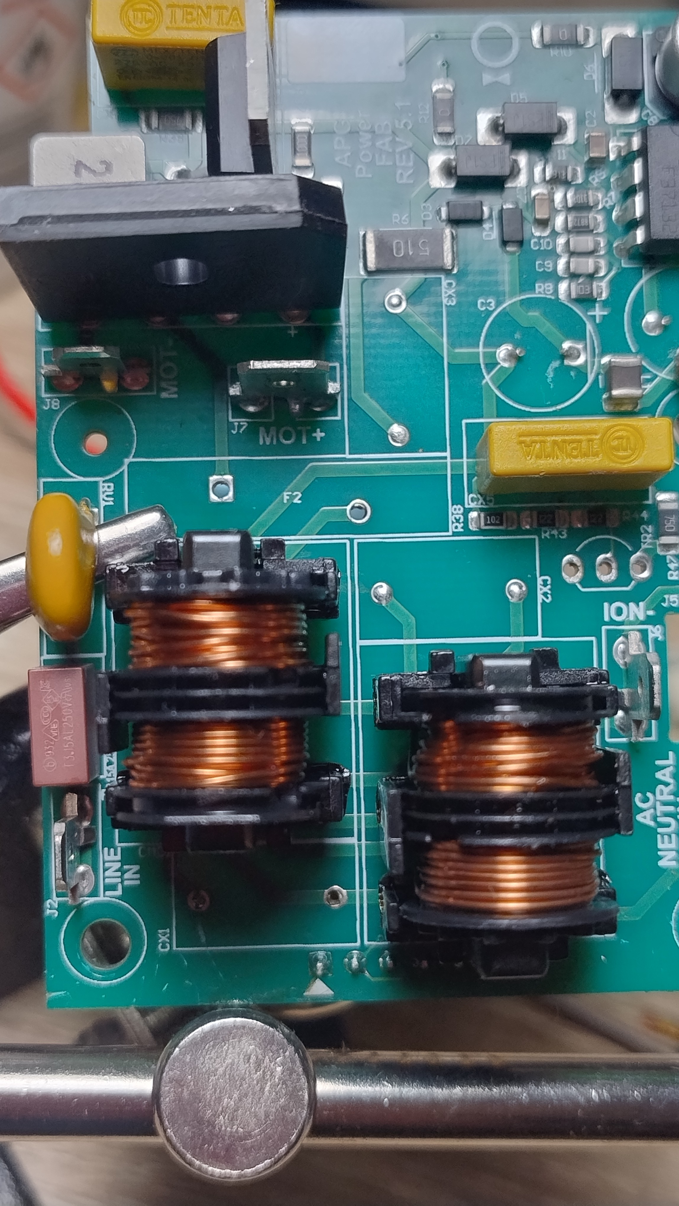
The rest of the power board is a fairly standard non-isolated switching supply built around a VIPER16, with an EMI filter on the input. Nothing that particularly caught my interest. If I’d stopped there I’d probably have a second working grinder by now, but I decided to take it apart all the way. Why? Because I found this.
The control board
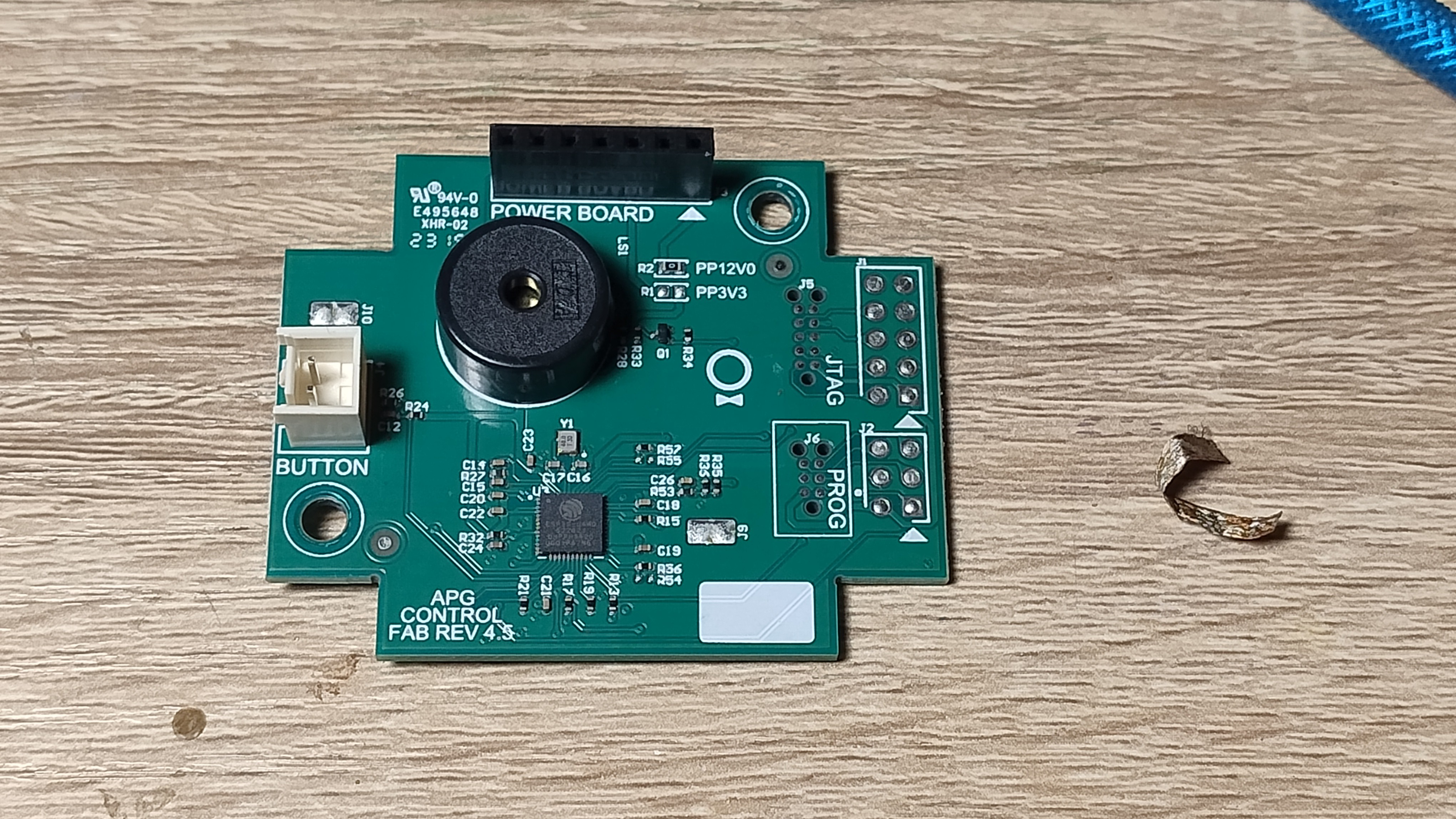
A control board with an ESP32-U4WDH on it! That meant I could write my own firmware and add interesting and useful (or just interesting) features – let’s say talking to Home Assistant, or remote control over a web socket. Maybe I could collect grinding statistics, or something else entirely. To be clear: even though the chip does Wi-Fi and BT, the grinder has no “smart” features and no app. In my eyes that’s one of its advantages. But if I can add those features on my own terms - that changes things. What encouraged me further were neat and big service pads labeled PROG. Once again I wanted to hug someone at Fellow and congratulate them on building something repairable, reusable and open to modification.
I started searching to see whether anyone had already had a go at this and… I found nothing. Nothing except the capacitor problems already mentioned and a thread from late 2023 on Home-Barista.com where someone describes their frustration with the sleep function the grinder has (after a longer stretch of inactivity you have to “wake” the grinder with a press of the grind button, and only the second press spins up the burrs. That function was present in the grinder I took apart too, and it really did breed a bit of frustration. Fortunately my new 2025 model no longer has it).
But back to the point - I found nothing. No DIY project where someone had done what I had in mind, no counter of grind-button presses, no total running time, not even a pinout for the board. That was a surprise, but it also got me excited. I had a UART-USB converter; with a bit of work I could map the pins and try to read the board’s firmware. I got to work.
Brain in a jar
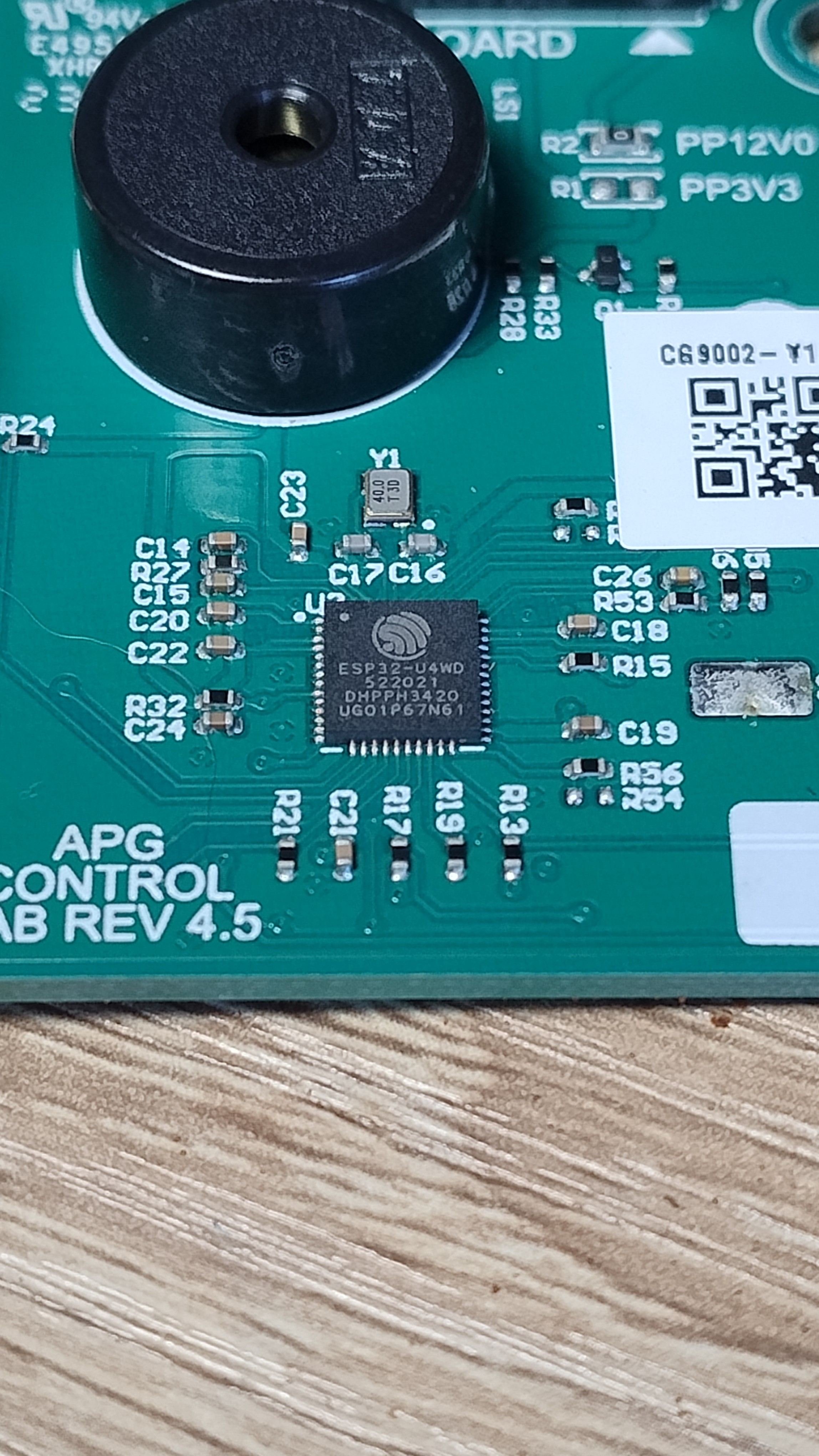
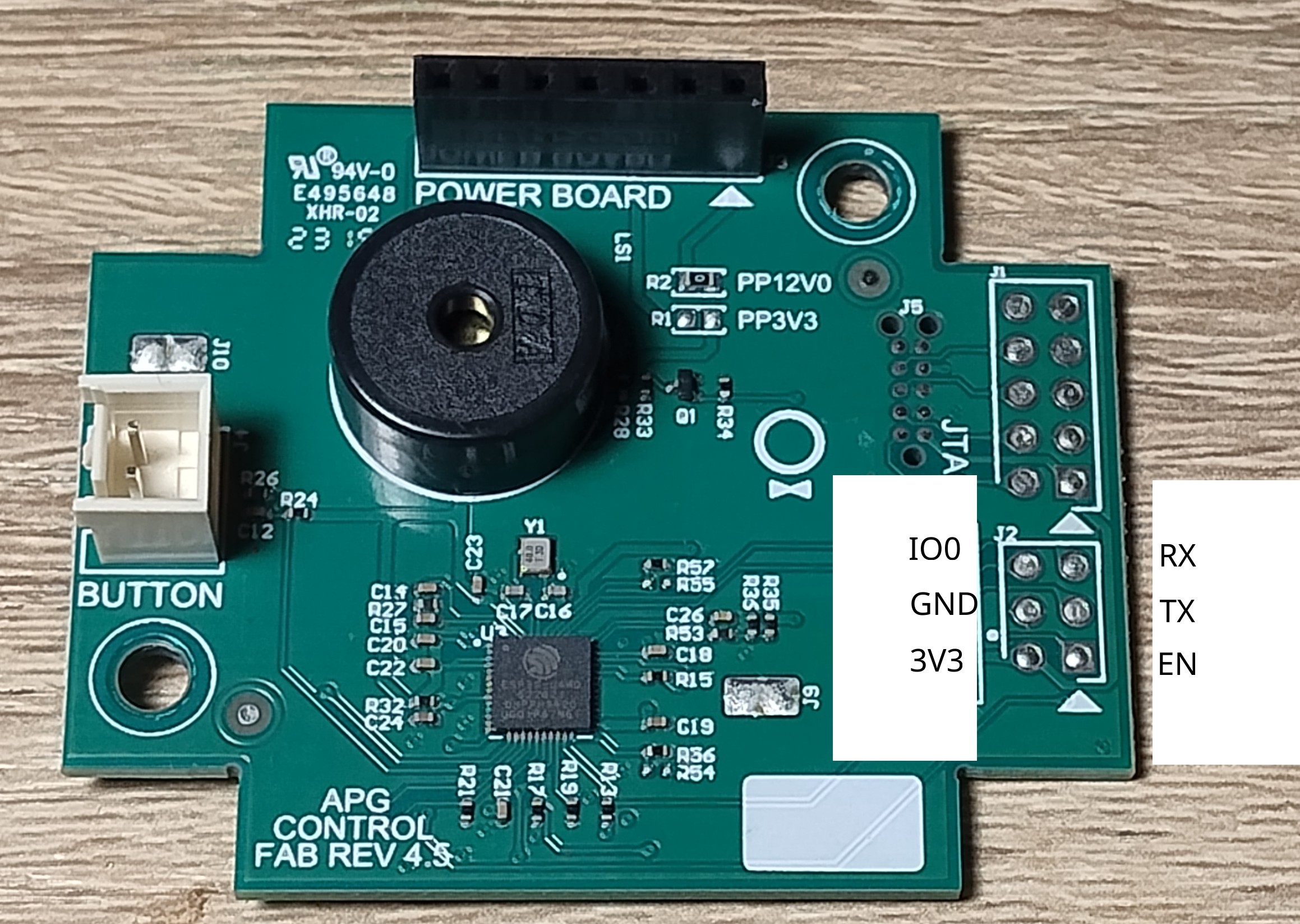
I started by writing the pins out on paper, numbering them per the IDC convention. Pin 1 is the square pad, additionally marked with an arrow; pin 2 sits opposite it, and so on. Then I moved on to identifying GND and 3V3.
Finding ground wasn’t hard. The first clue was a small cross visible on one of the pads of the J2 field.
Why J2 and not PROG? You can see on the board that both fields are connected 1:1, and a multimeter test confirmed it. The PROG field, J6, is most likely there for “bed-of-nails” testing.
Second clure – crosses - one visible on pad 4, several on the J1 field (JTAG). J4 is the connector for the button that starts the grinder - one pin is a controller GPIO, and maybe the other one is ground? Sure enough: the bottom pin (in the orientation from the photo) and all the cross-marked pads are connected together. A net that extensive has to be the circuit’s common ground. First pin identified.
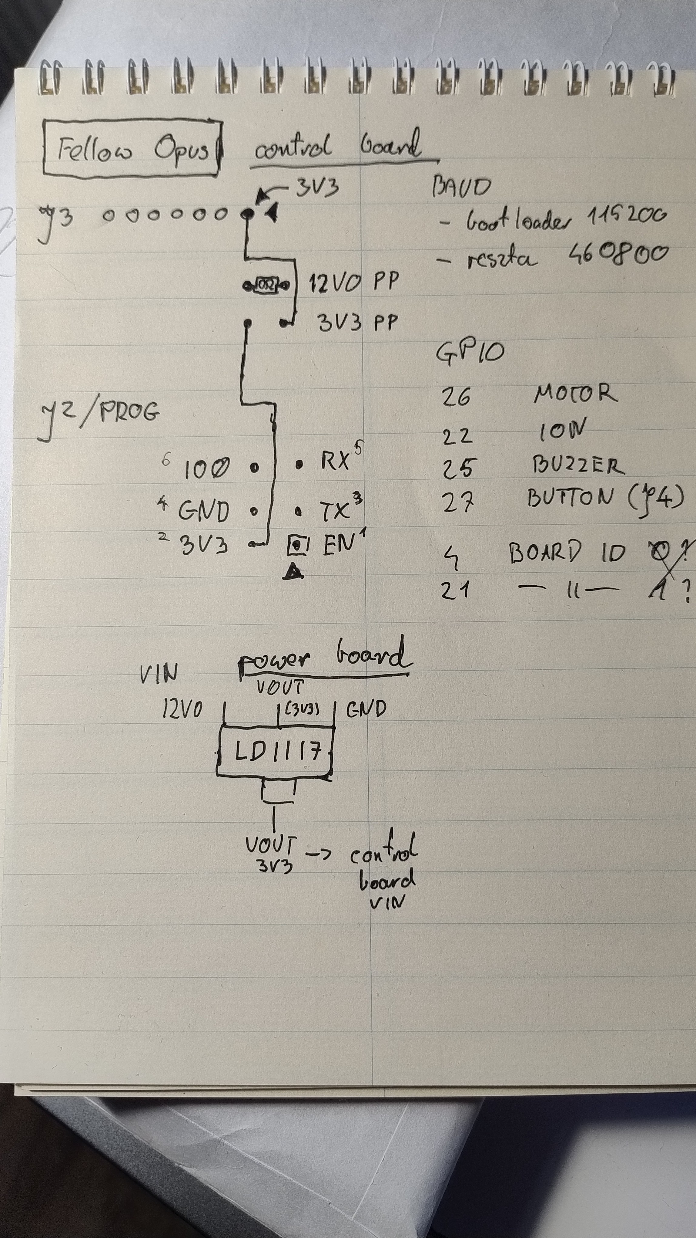
Now VCC. On the board you can spot PP3V3 and PP12V0 - the latter bridged with a 0 Ω resistor. Maybe one of the 3V3 pads is connected to one of the J2 pads? Yes! There’s continuity between the left PP3V3 pad (in the orientation from the photo) and pad 2 on J2. The right PP3V3 pad, in turn, has continuity with the tab of the LD1117, which in the SOT-223 package is connected to VOUT (3V3). The LD1117 sits on the power board, on the underside.
An important warning here: the appliance is Class II and the original supply topology has no galvanic isolation from the mains. With the power board connected, the entire electronics - the ESP32 headers included - sits at mains potential. Connecting USB to a powered device is dangerous. To put it plainly: don’t want to fry your computer (or yourself)? Unplug the device, wait for the capacitors to discharge, and disconnect the control board from the power board. All the work described here was carried out with the power board physically disconnected, from an external 3.3 V supply.
Back to it. I now know where the supply input is.
Moving on - the EN pin. Per Espressif’s documentation there should be a 10 kΩ pull-up between 3V3 and EN, with a capacitor to GND along the way. The only pin giving those readings on the multimeter is pad 1, the one marked with a square. 50% of the pins I need, identified. While I was at it I noticed that between 3V3 and pad 6 there’s most likely a 1.8 kΩ resistor, so this may well be GPIO0. Shorting that pin to ground will be needed to enter programming mode. Two pads left, 3 and 5. With those I noticed they have diodes on them - pushing current one way shows no connection on the meter, the other way shows continuity. That suggests these are pads connected directly to the chip. So one is RX and the other TX. Let’s check.
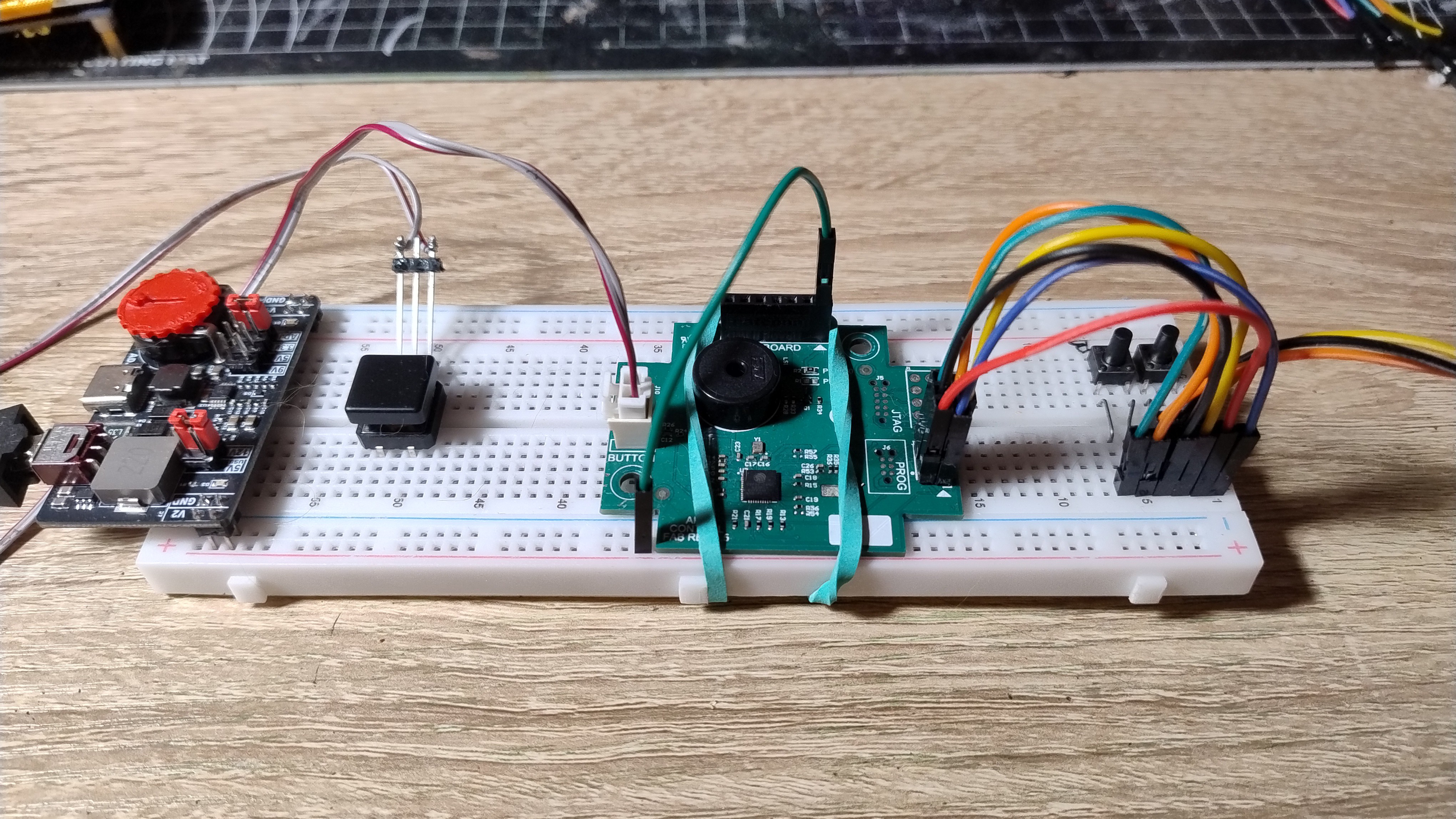
To make life easier I built this contraption. You can see the Boot and Reset tact switches shorting the relevant pins to ground (reset - EN-GND; boot - IO0-GND) and a third, larger one wired to J4, the connector for the grind button. I soldered pin headers into the pads and connected the UART-USB converter to them (a CP2102 from Waveshare). To begin with I connected only the converter’s RX pin - I still didn’t know which pad on the board was RX and which was TX, and I wanted to avoid conflicts. I hooked RX up to pin 3. I plugged the whole thing into a USB port, fired up a serial monitor at 115200 baud, hit reset on the board and…
I got a bootlog! After that it was garbage, but the first lines were readable. So I’d hit the board’s TX on the first try. I could connect the remaining pins and move on to dumping the firmware. The brain pulled out of the grinder was now floating in a jar on my desk, and I could do whatever I liked with it.
$ pio device monitor -p /dev/ttyUSB0 -b 115200
--- Terminal on /dev/ttyUSB0 | 115200 8-N-1
--- Available filters and text transformations: debug, default, direct, hexlify, log2file, nocontrol, printable, send_on_enter, time
--- More details at https://bit.ly/pio-monitor-filters
--- Quit: Ctrl+C | Menu: Ctrl+T | Help: Ctrl+T followed by Ctrl+H
ets Jul 29 2019 12:21:46

rst:0x1 (POWERON_RESET),boot:0x13 (SPI_FAST_FLASH_BOOT)
configsip: 188777542, SPIWP:0xee
clk_drv:0x00,q_drv:0x00,d_drv:0x00,cs0_drv:0x00,hd_drv:0x00,wp_drv:0x00
mode:DIO, clock div:2
load:0x3fff0030,len:7144
load:0x40078000,len:13200
load:0x40080400,len:4580
entry 0x400806f4
Getting out whatever I can
I wanted to do two things. First, share my findings (just maybe that person who back in 2023 was looking for an answer to their grinder problems is still looking). Second - write my own firmware. I already had an idea. I’d recreate the grinder’s original functions (minus the sleep-on-inactivity) and add my own: Bluetooth and/or Wi-Fi connectivity and advanced control over a web socket. Precise grind-time setting with a slider, and statistics: length of the last grind, total grinding time (since the firmware change), maybe estimated energy use.
For that I needed to learn more about the existing software. Above all: which ESP32 pins the motor, the ionizer,
I forgot to mention that the grinder has a YFA-223B ion generator - it steps the mains voltage up to ±3 kV and feeds it to thin needles in the grinder’s chute, which is meant to “pull” the electrostatic charge out of the ground beans. The feature worked, but the needles quickly got coated with coffee, which insulated them very effectively.
the button and the buzzer are connected to. Plus, if anything else is wired to the board - if some measurement is being taken through the ADC, say - I wanted to know about it.
First I had to read the rest of the logs from the chip, which so far I’d only seen as garbage in the terminal. The culprit was a mismatched baud rate - while the bootloader transmits at 115200 as standard, the rest was available at a different one. By trial and error I established that the rest of the board speaks at 460800 baud. I switched over
pio device monitor -p /dev/ttyUSB0 -b 460800
reset the board, and saw great news on the screen - a boot log containing information about the pins and their connections.
- Motor - GPIO 26
- Ionizer - GPIO 22
- Button - GPIO 27
And two pins responsible for the Board ID - 4 and 21. In my case the Board ID is [0,0]. I couldn’t be bothered to work out which pin is the first bit and which is the second.
There was also a curiosity - a leftover from the hello world example in ESP-IDF. The developers at Fellow kept a piece of tutorial code for themselves. I can’t really blame them; quick chip identification matters. “This is esp32 chip with 2 CPU core(s), WiFi/BT/BLE, Silicon revision 3, 4MB embedded flash”. The only thing I was missing was the buzzer. I did see the line “BEEP: Starting MailboxTask”, but the pin had to be defined somewhere else. The monitor was also showing logs relating to the motor. I was curious what would happen when I pressed the grind button.
A few interesting things: a message about a short button press, about the sleep timer being stopped, the ionizer and the grinder being switched on, and the motor’s running-time counter starting. According to the manual the grinder must not run for more than 6 minutes in total within a 10-minute window, and to work that out Fellow used a moving average. I also noticed that the ionizer is switched off 5 s after the motor stops. That information was valuable to me if I wanted to recreate the grinder’s behavior in my own firmware.
Hunting for the buzzer
To get to the buzzer I had to download the flash. In download mode I used
esptool --port /dev/ttyUSB0 --before no-reset --after no-reset \ read-flash 0x0 0x400000 opus_dump.bin
From that dump I extracted the partition table
xxd -s 0x8000 -l 256 opus_dump.bin
Next - I carved out the application partition
dd if=opus_dump.bin of=factory.bin bs=4096 skip=16 count=256
xxd -l 32 factory.bin
I generated the ELF file
python3 esp32_image_parser.py create_elf ~/opus_dump.bin
-partition factory -output opus_factory.elf
and verified it
readelf -h opus_factory.elf
And however much that sounds like just a few steps - and for someone more advanced in programming it might really be just a few steps - for me it was a hard task. I leaned heavily on AI. I needed explanations for terms I didn’t know, instructions on how to carry out each step, and what to actually do with the results. My adventures with electronics and embedded programming so far had been far simpler - I wrote simple programs that pulled data from sensors and displayed it on little screens, I built a tracked drone controlled remotely over Wi-Fi or ESP-NOW. Nothing as complex as trying to disassemble and decompile a program written by someone else. Even so, leaning on AI like a crutch, I decided to keep shuffling forward and imported the ELF into Ghidra.
I’ll skip over what I did in that program - a lot of random clicking and pasting pseudo-C++ into Claude. In the end I managed to get as far as the error message “Buzzer failed to init”, and from there to a function whose last argument is “25”. The pattern “the last argument holds the GPIO number” was present in the other modules, the ones I’d confirmed earlier from the log. So I was almost certain the buzzer was wired to pin 25, but final confirmation only came from writing my own code.
That turned out to be more complicated than the firmware writing I was used to. For instance, I couldn’t simply use PlatformIO to upload firmware to the board. For some reason the board would only talk to the esptool I had installed system-wide (v5.2); the version bundled with PlatformIO (5.3) didn’t work. There was also a reset problem - since the board has no auto-reset circuit (the converter’s DTR/RTS lines don’t drive EN and IO0), I firstly had to remember every time to put it into download mode by hand, and secondly I had to use the --before no-reset --after no-reset flags. Everything else, though, behaved normally - the simple program worked.
#include <Arduino.h>
#define BUTTON_PIN 27 // grind button, active low
#define BUZZER 25
int lastState = HIGH;
int currentState;
unsigned long lastChange = 0;
const unsigned long DEBOUNCE_MS = 30;
void setup() {
Serial.begin(115200);
delay(500); // time for the port to stabilise
Serial.println();
Serial.println("=== Opus test: button GPIO 27 ===");
pinMode(BUTTON_PIN, INPUT);
pinMode(BUZZER, OUTPUT);
lastState = digitalRead(BUTTON_PIN);
Serial.printf("Initial state: %s\n", lastState == HIGH ? "HIGH" : "LOW");
}
void loop() {
currentState = digitalRead(BUTTON_PIN);

if (currentState != lastState && (millis() - lastChange) > DEBOUNCE_MS) {
lastChange = millis();
if (currentState == LOW) {
Serial.printf("[%lu] PUSHED (HIGH -> LOW)\n", millis());
tone(BUZZER, 4000);
Serial.print("beep beep\n");
} else {
Serial.printf("[%lu] RELEASED (LOW -> HIGH)\n", millis());
noTone(BUZZER);
Serial.print("...\n");
}
lastState = currentState;
}
delay(5);
}
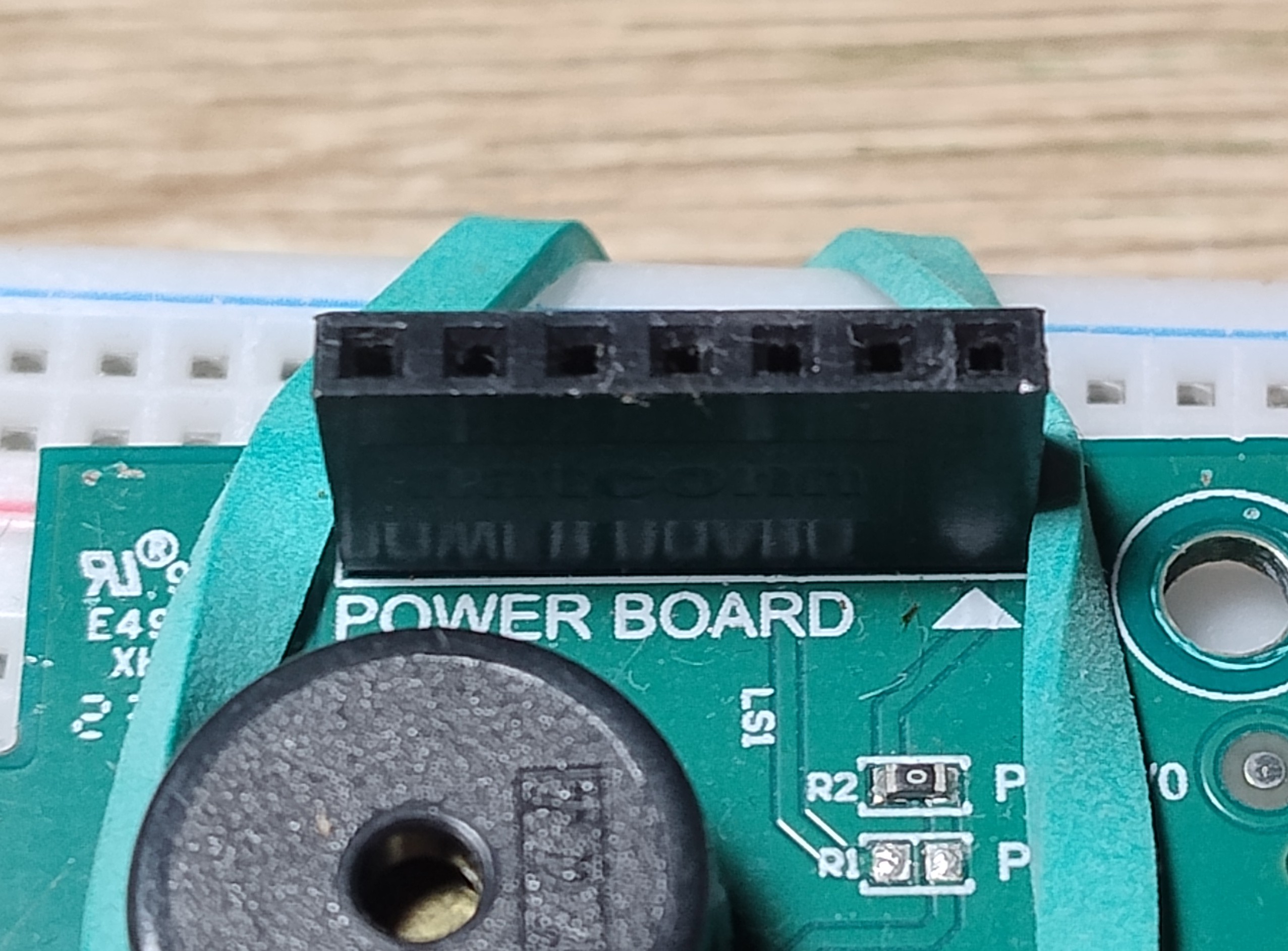
I verified something important along the way: the board itself runs perfectly well on 3.3 V alone, but the buzzer hangs off the 12 V rail, the same one that feeds the LD1117. The 12V0 pin is at the start of the J3 connector and is marked with arrow as the first one.
An hour before it sleeps
So what about the function one of the home baristas asked about on the forum? Digging around in Ghidra confirmed what the log had already hinted at. Once grinding - or any other activity - ends, a countdown starts. The grinder counts down 10 seconds, and after that it announces that it’s trying to go to sleep. That period lasts an hour; past it, the grinder first has to be woken with a single press of the grind button. The microcontroller then instantly catches up on the timer calls it missed, the overheating protection among them. The second press is a normal grind. There’s only one conclusion here: the function they were asking about on the forum is baked into the grinder’s firmware, and changing it means changing the software.
Next steps
This is the first part of my adventure with the grinder. I’ve taken it apart and I now know what’s inside. In the second stage, and in the project updates to come, I’ll describe my attempts at building an alternative, working firmware - which I’ll publish on my Codeberg.