Arnov Sharma

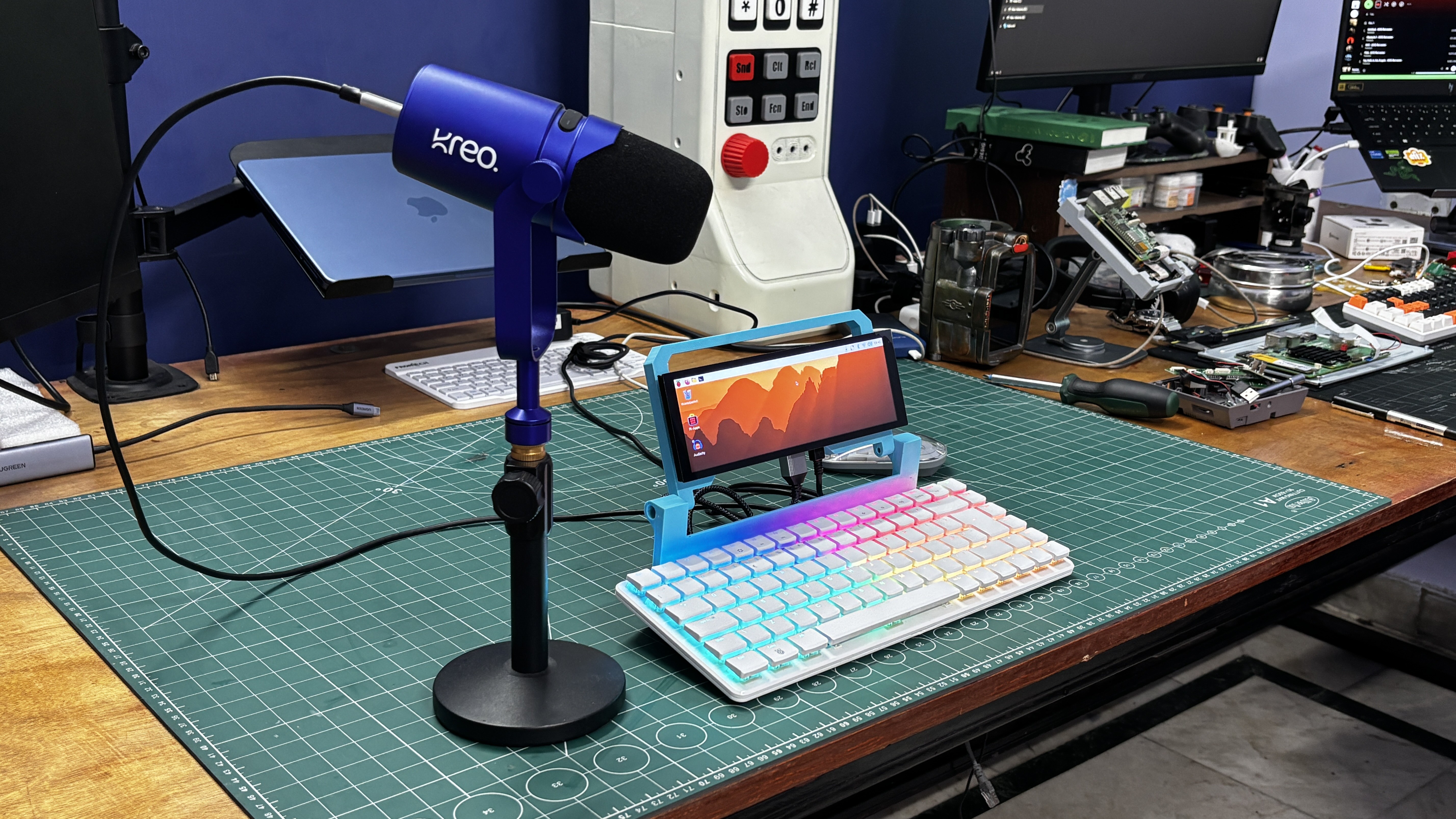
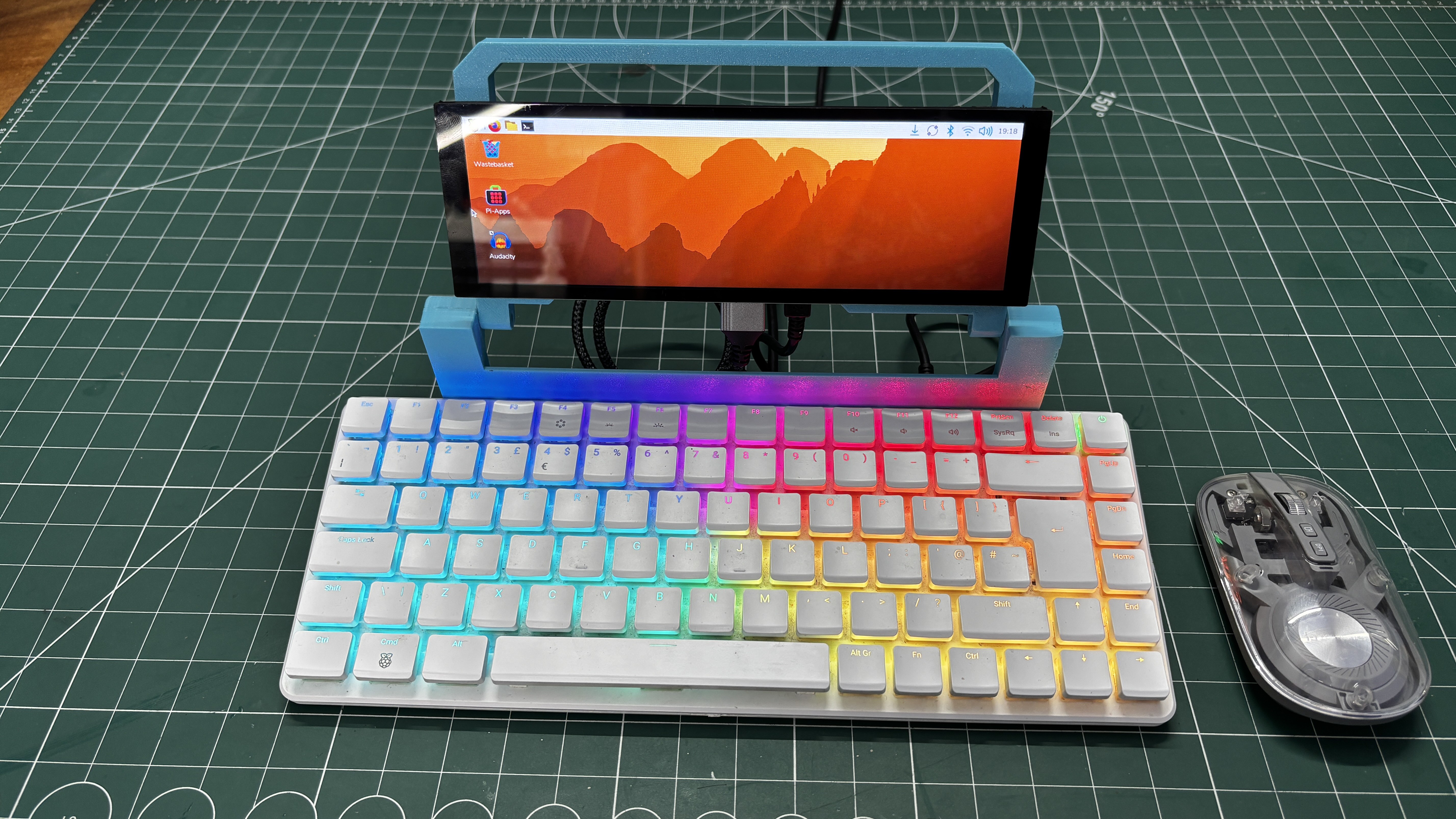
The main reason for making this project was actually pretty simple. I had already been using the Pi 500+ with my USB recording microphone for voice-over work, and I kept thinking that it really needed a screen of its own.
The Raspberry Pi team has done a great job with the Pi 500+. It packs a lot into a keyboard form factor and even comes with a mechanical keyboard. But I felt it was missing one thing, which was a built-in display.
So, rather than waiting for a version with a screen, I decided to make one myself.
MATERIALS REQUIRED
These were the components used in this project.
- Raspberry Pi 500 Plus 16GB 256GB Variant
- Waveshare 7.9-inch HDMI Touch Screen
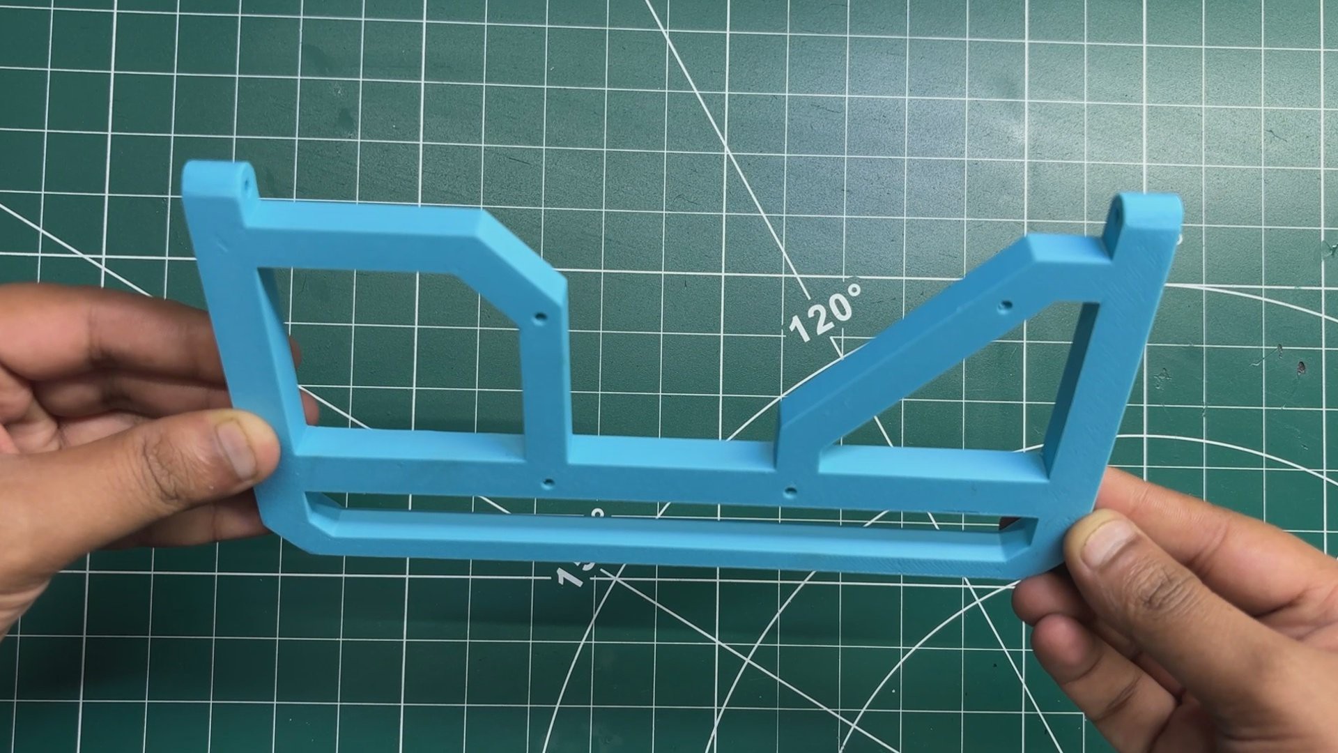
- 3D Printed Parts
- HDMI to Mini HDMI Cable 200mm
- USB to Micro USB Cable 200mm
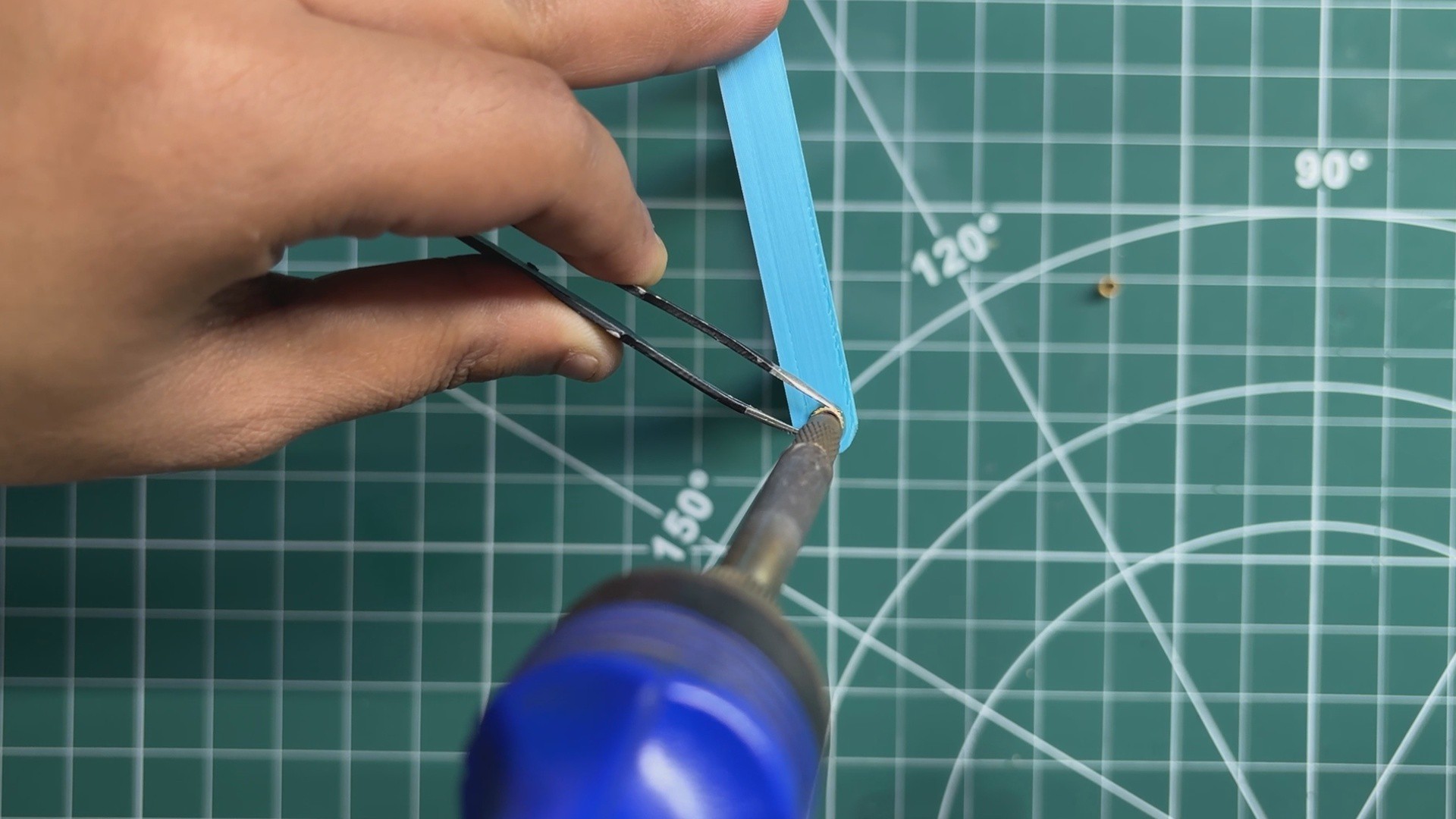
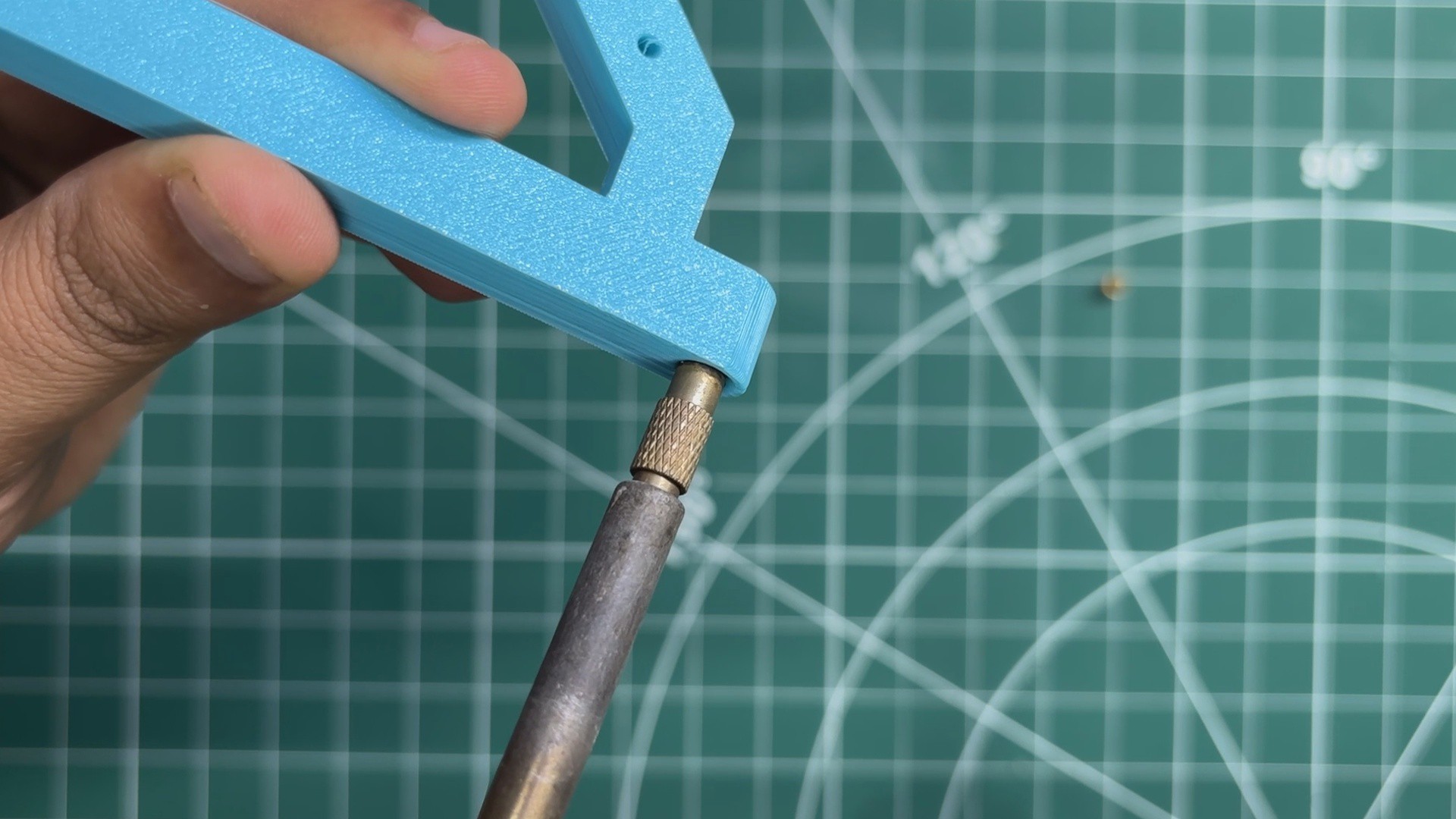
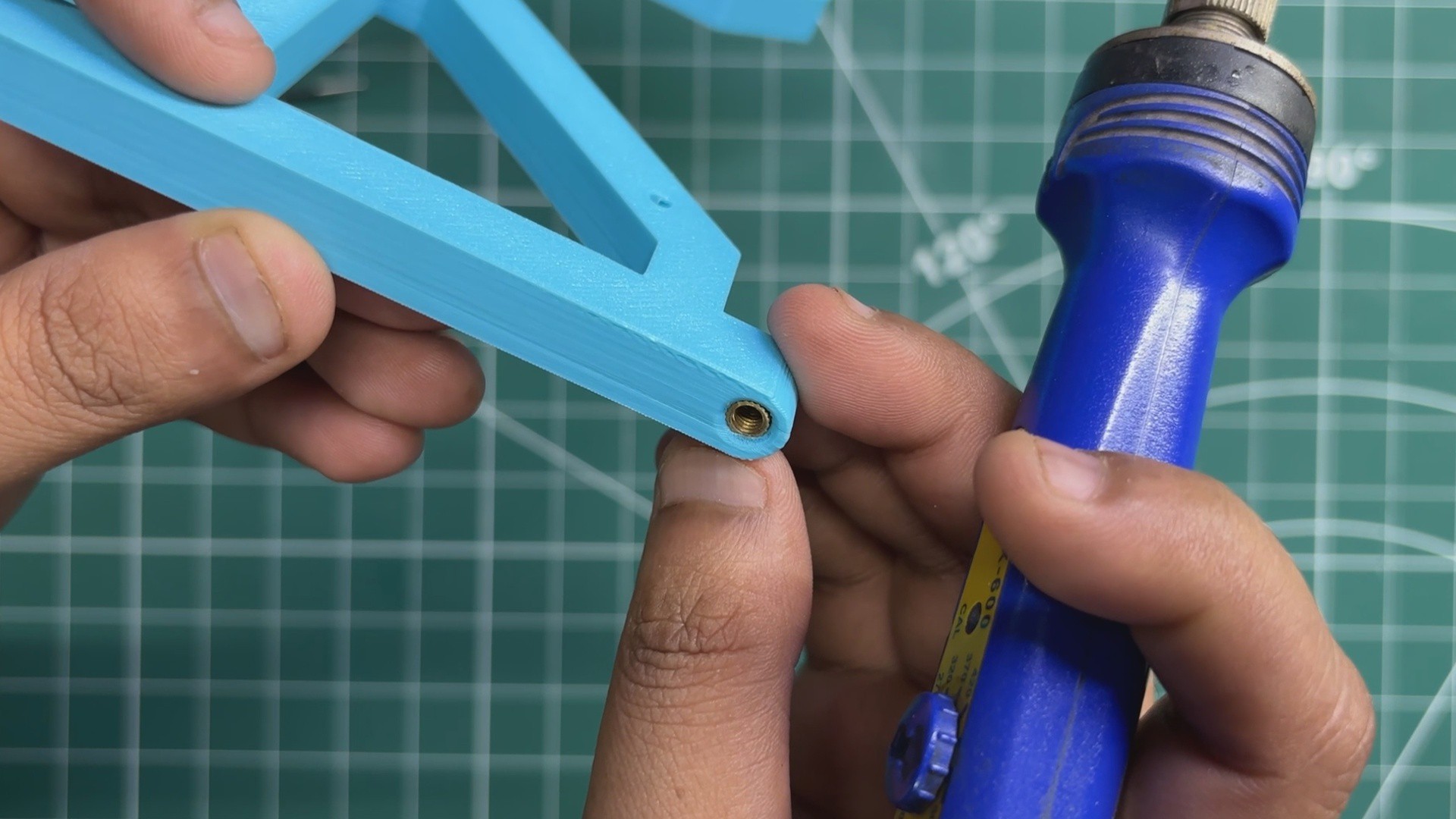
- M3 Threaded Inserts
- M3 Bolts
- M2.5 Bolts
PREVIOUS PROJECT—RASPBERRY PI 1000
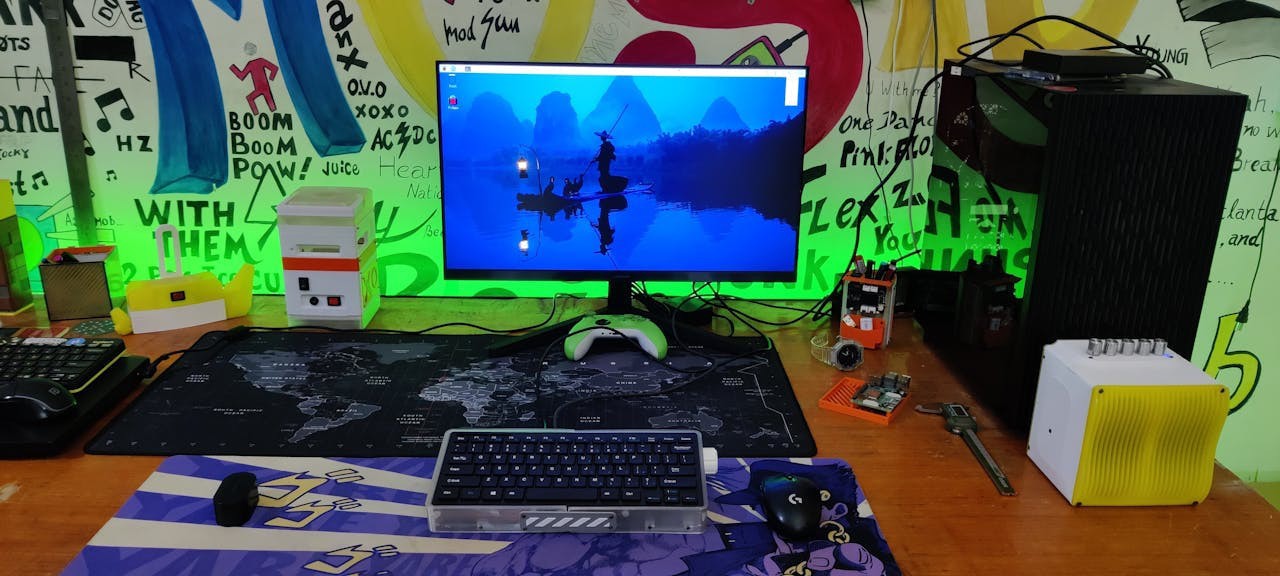
Before making the Raspberry Pi 10,000, I had already experimented with building my own keyboard computer with the Raspberry Pi 1000.
The Pi 1000 was my DIY alternative to the Raspberry Pi 400, combining a Raspberry Pi 5 4GB, an NVMe SSD, and a custom keyboard enclosure into a compact keyboard computer. I used a PCIe M.2 shield to connect the NVMe drive, which significantly improved the system's boot and storage performance.
The setup could boot to the desktop in around 5–6 seconds, while the Gen 3×4 NVMe SSD offered read and write speeds of up to 1600 MB/s and 1100 MB/s, respectively.
I also added a custom volume knob controller, built from scratch using a Seeed Studio XIAO SAMD21 microcontroller and HID protocol to control the system volume.
But this was an old project; the current Raspberry Pi 10,000 is more of a MOD Project.
HARDWARE—Raspberry Pi 500 PLUS
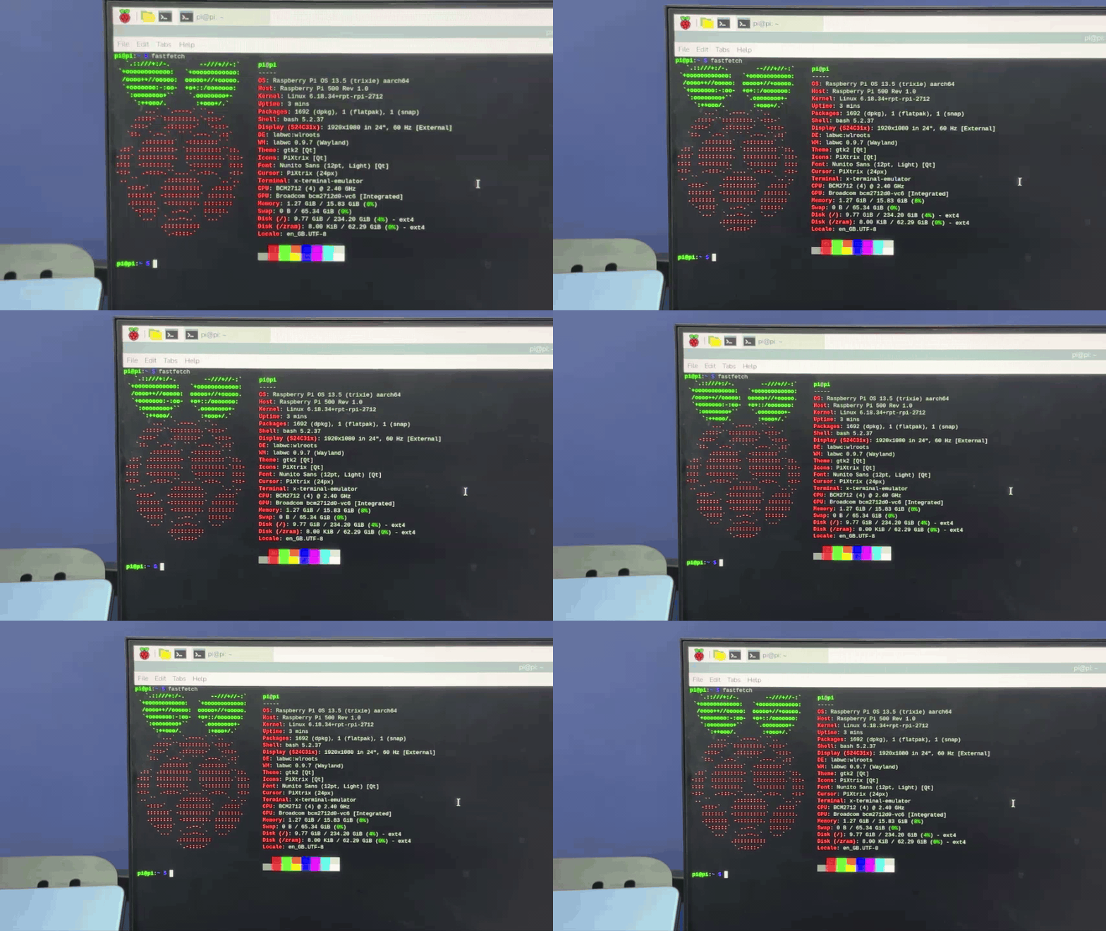
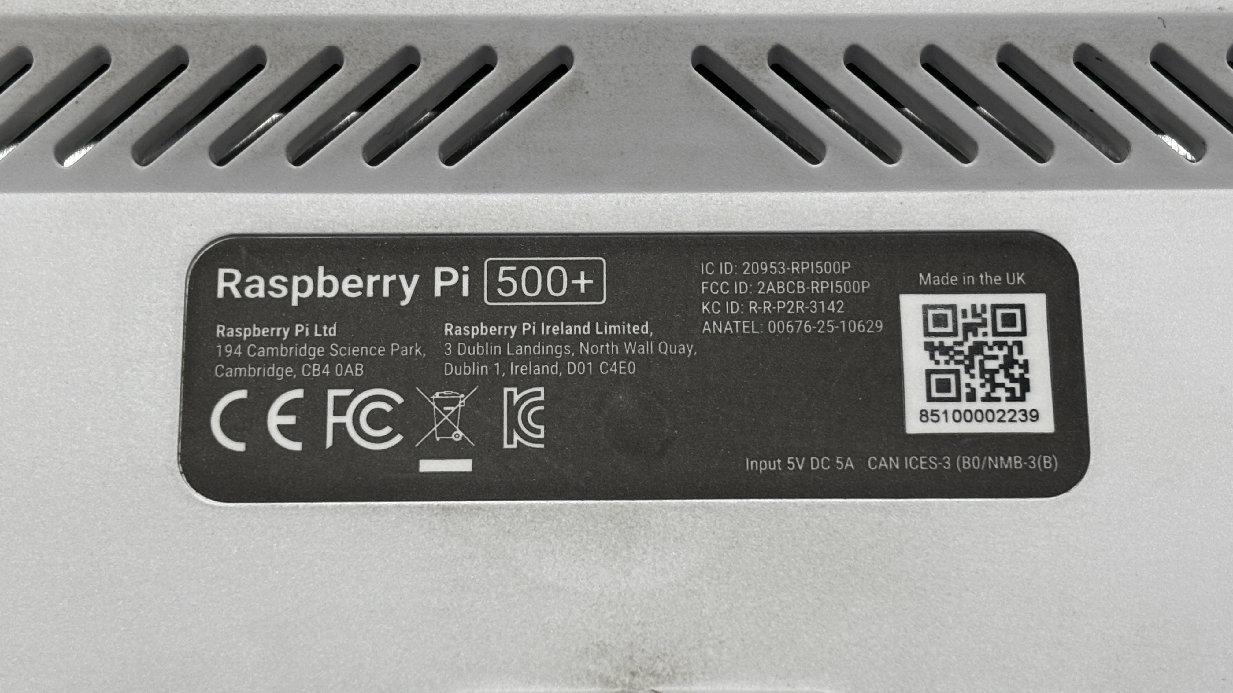
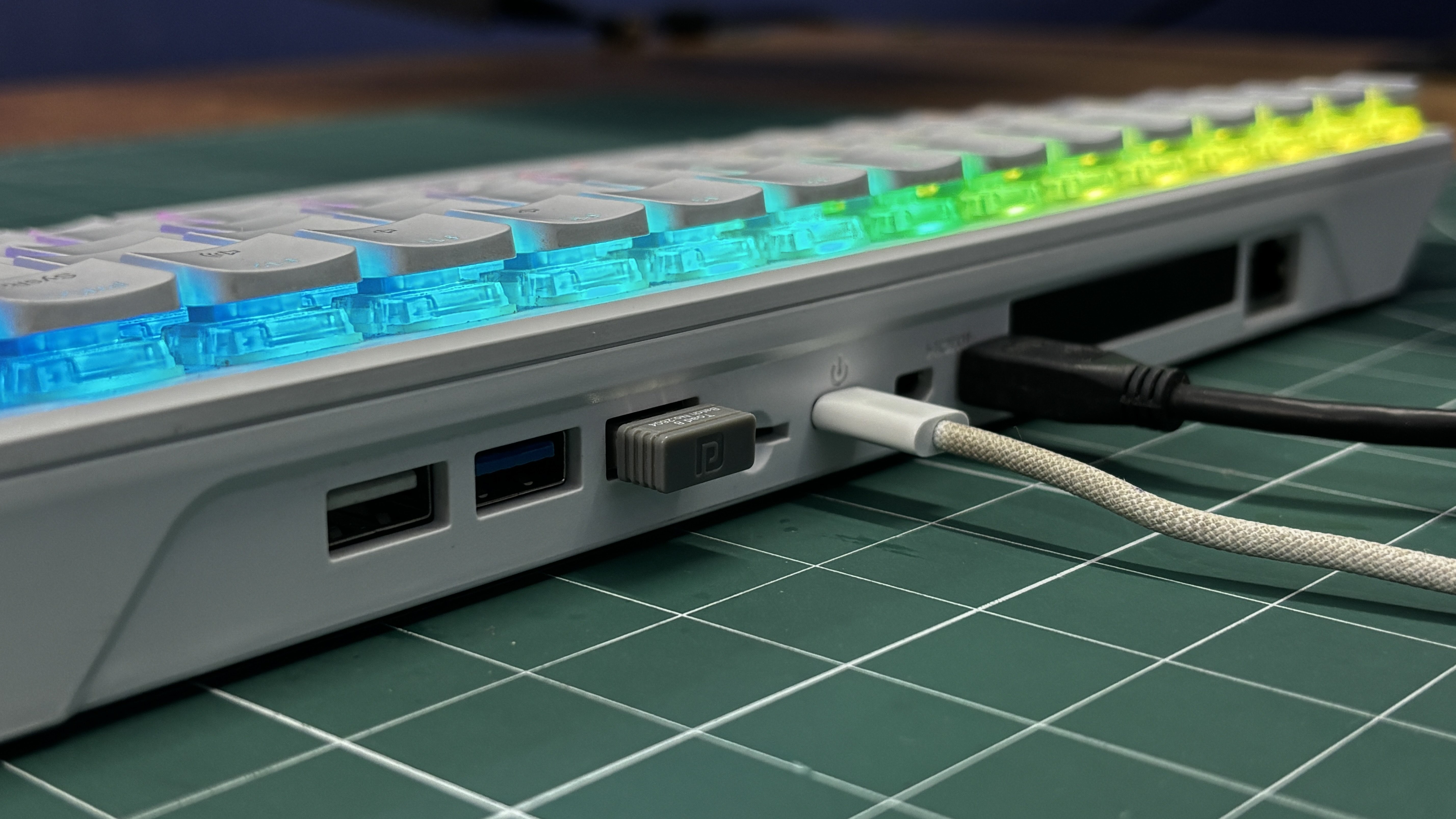
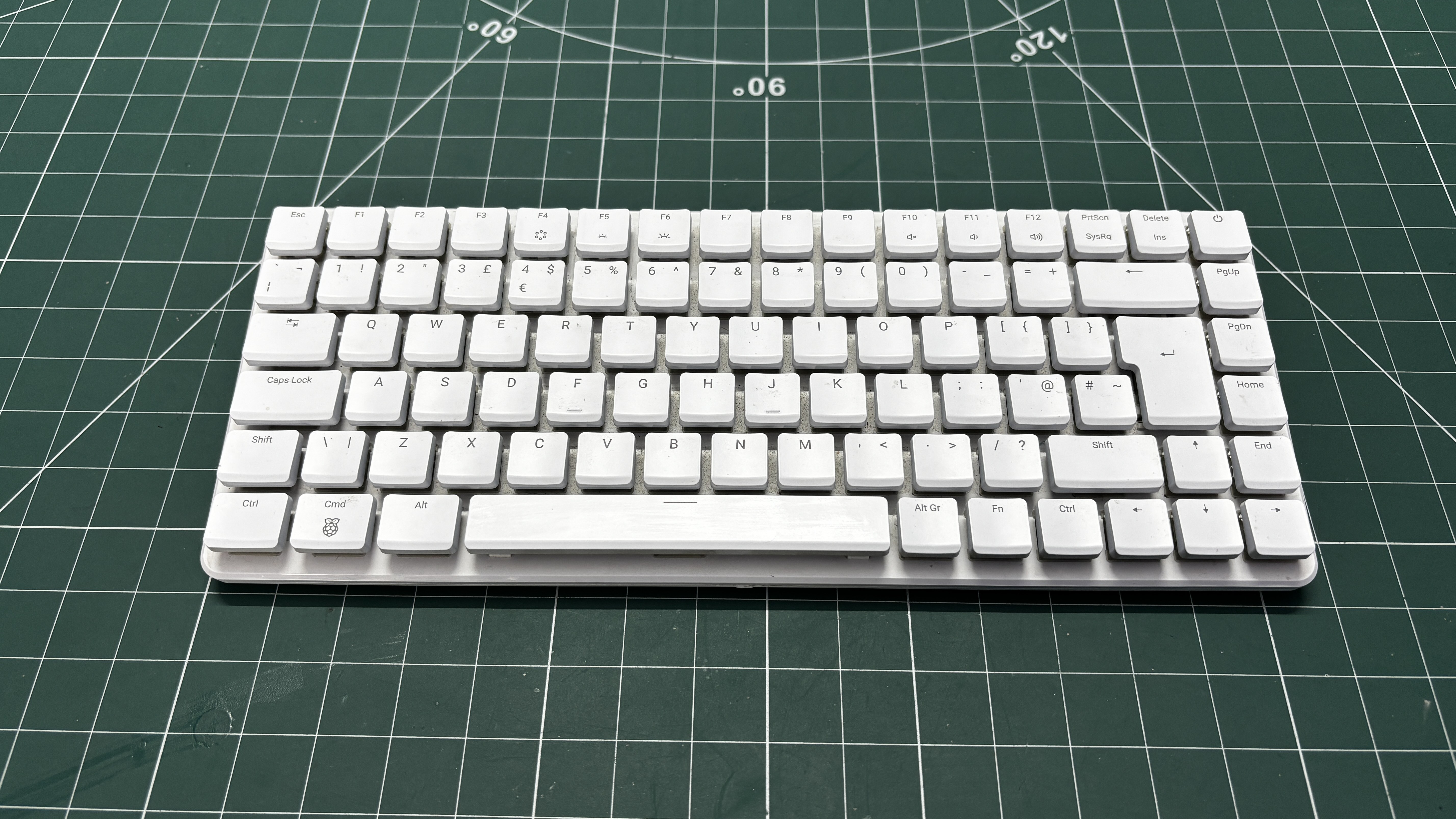
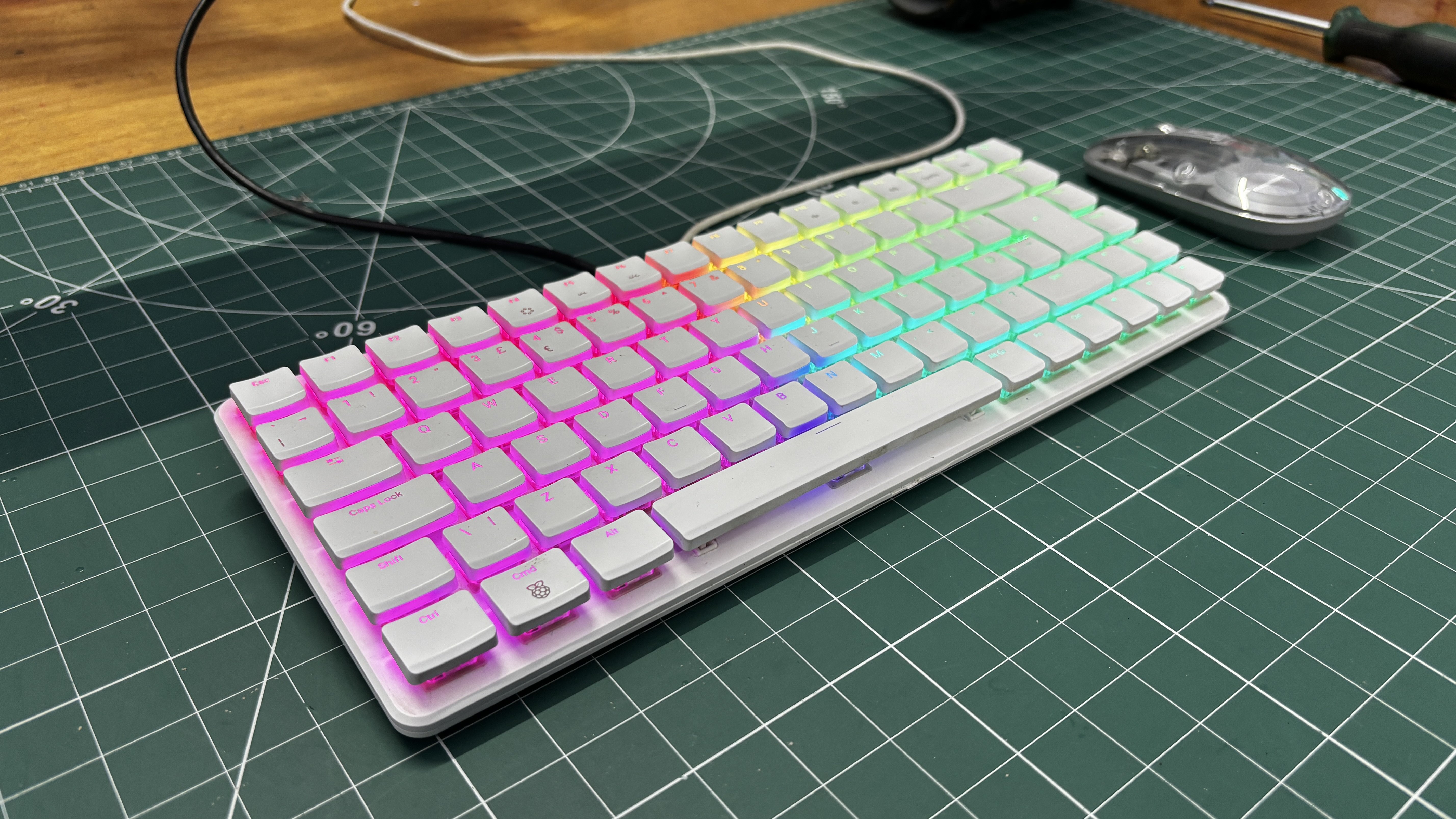
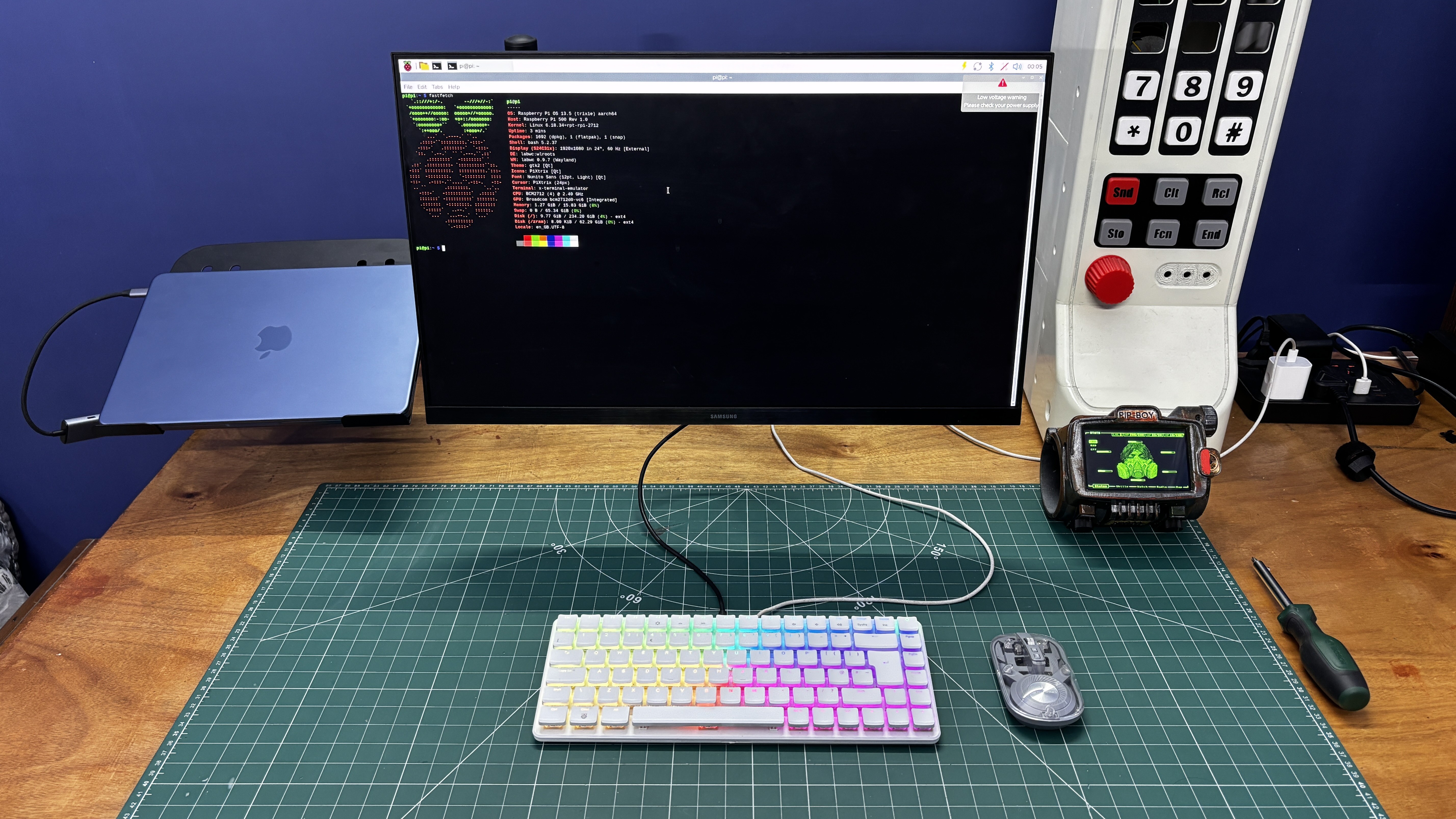
The star of this project is the new Raspberry Pi 500+, which is a Raspberry Pi-based keyboard computer. It is part of their keyboard lineup of single-board computers, with some new features added. The most noticeable addition is the mechanical keyboard with addressable RGB LEDs. It uses the same Broadcom BCM2712 as the Raspberry Pi 5, plus an onboard NVMe SSD.
The BCM2712 is a quad-core 64-bit ARM Cortex-A76 processor clocked at 2.4 GHz. The VideoCore VII GPU handles graphics and supports hardware-accelerated graphics and high-resolution displays.
The Pi 500+ variant used in this project comes with 16 GB of LPDDR4X RAM and 256 GB of onboard NVMe storage, providing plenty of memory and storage for desktop applications, media, development, and other demanding workloads.
For connectivity, it includes dual-band 802.11ac Wi-Fi, Bluetooth 5.0/BLE, Gigabit Ethernet, and multiple USB ports. It also features two micro-HDMI ports, allowing it to drive external displays, along with a 40-pin GPIO header for connecting additional hardware.
HARDWARE—WAVESHARE 7.9" HDMI TOUCH DISPLAY
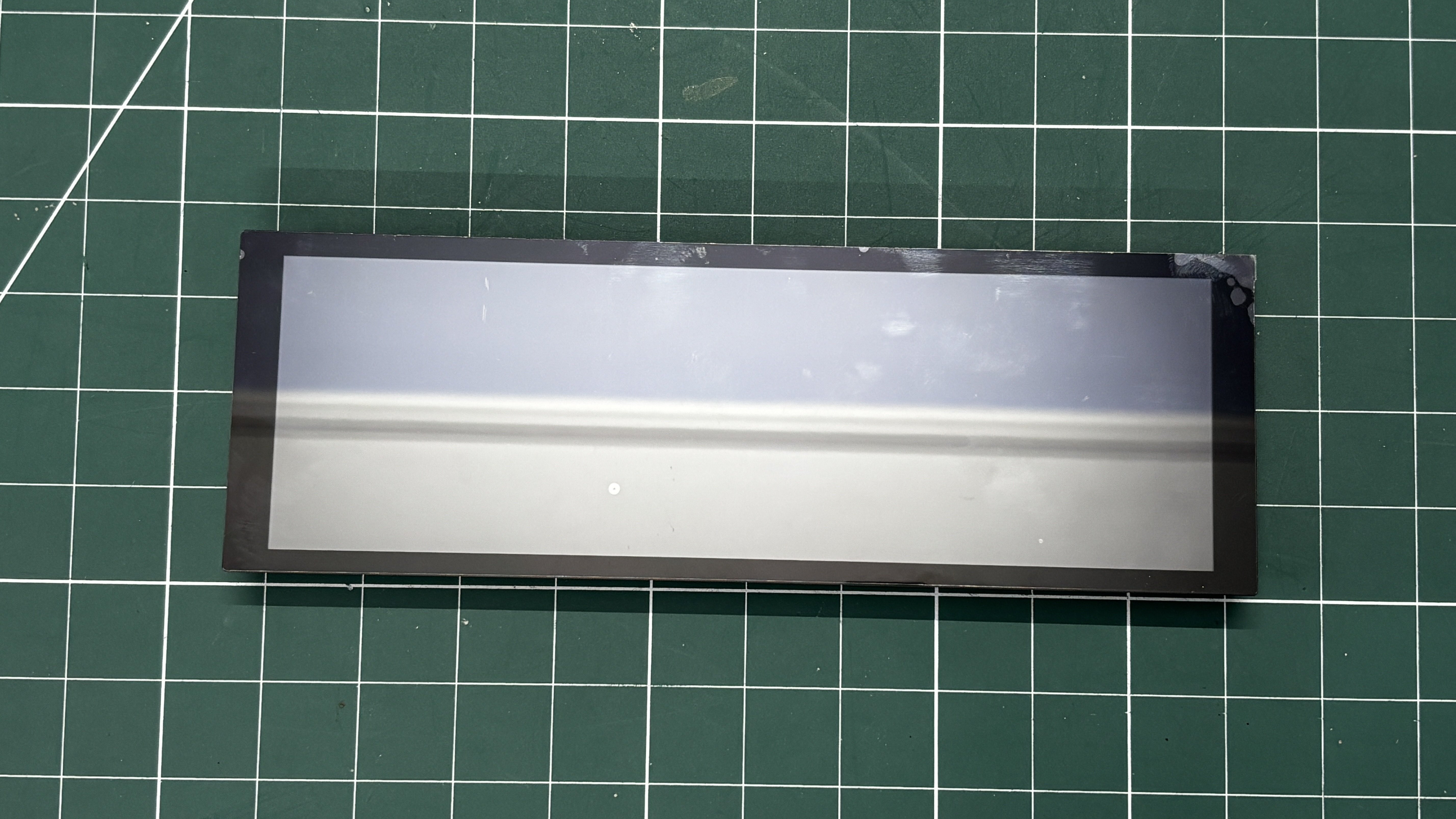
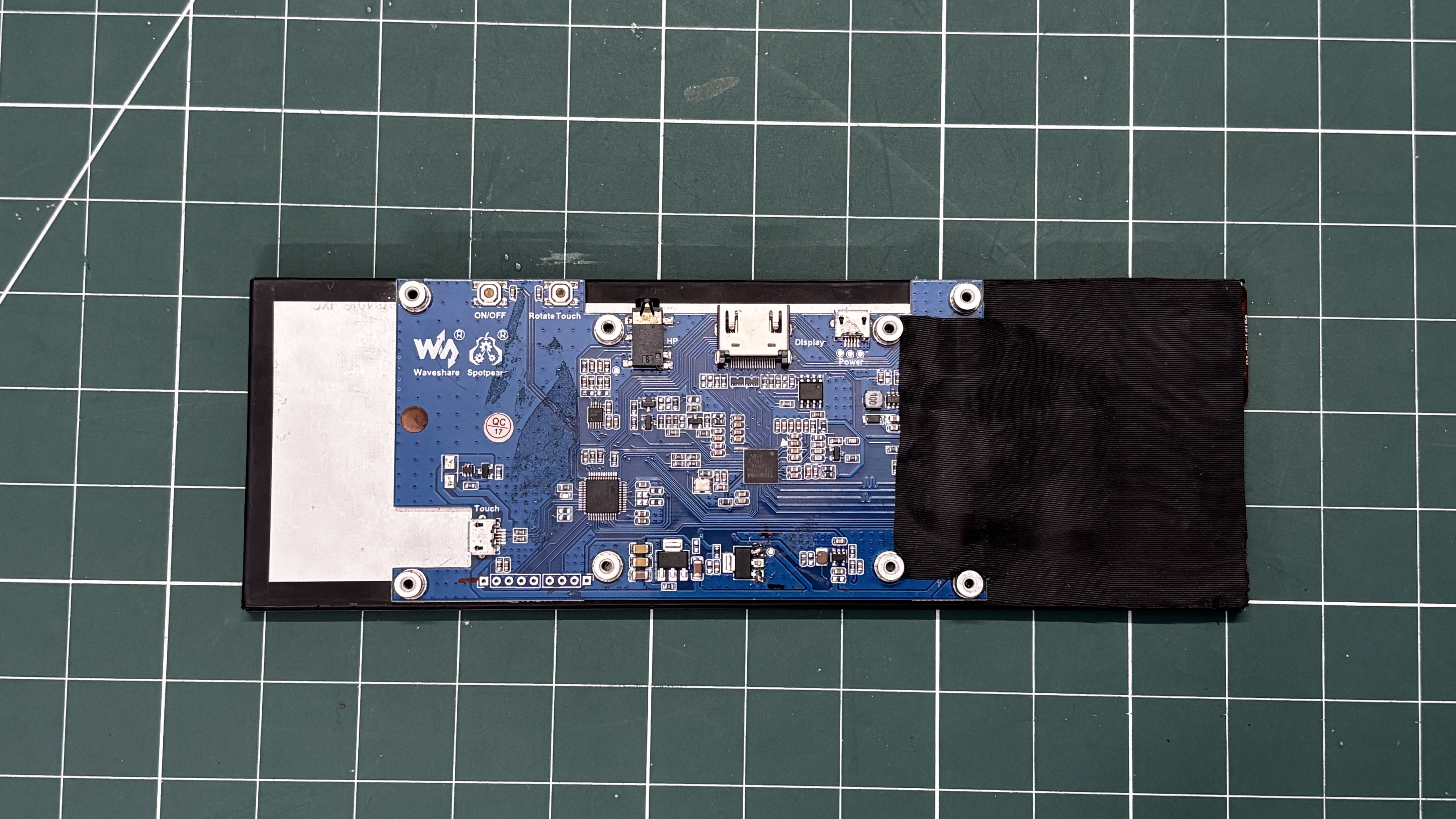
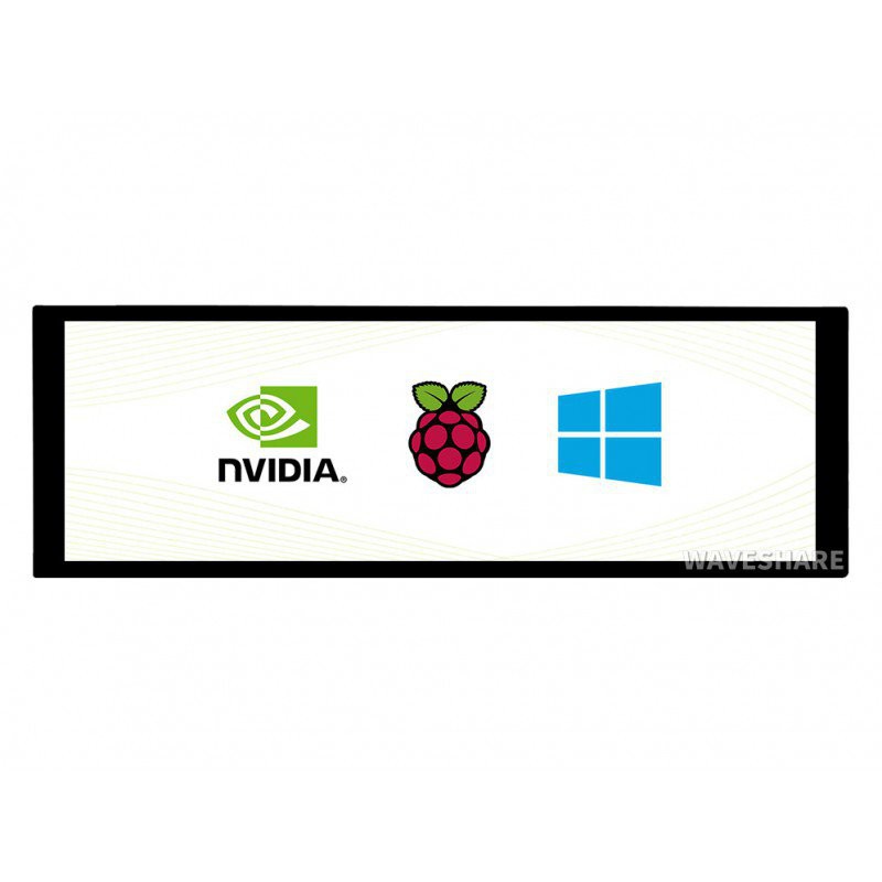
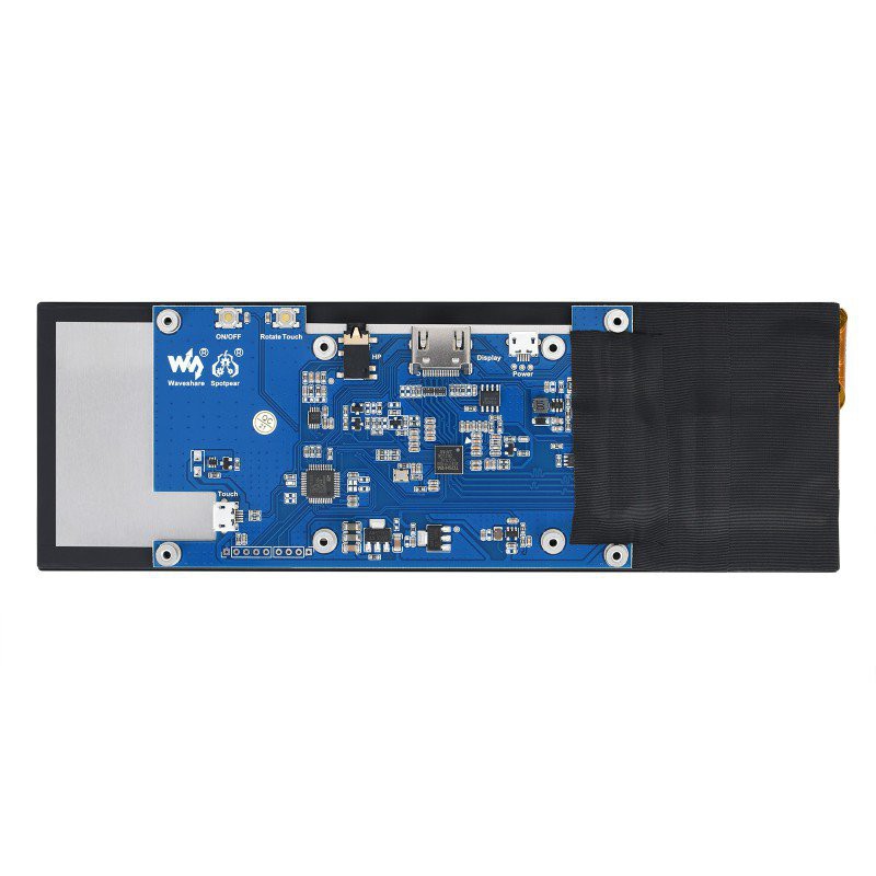
For the display, I wanted to go with something a little different. Instead of using a conventional 7-inch or 10-inch 1920×1080 panel, I went with a 7.9-inch 400×1280 HDMI display from Waveshare. The unusual aspect ratio gives the project a completely different look and makes much better use of the available space.
The display uses an IPS panel with a 400×1280 hardware resolution and features a 5-point capacitive touchscreen covered by a toughened glass panel with up to 6H hardness. It connects to the Raspberry Pi through HDMI, while the touch interface provides an additional USB connection.
The display is also quite versatile. When connected to a Raspberry Pi, it supports operating systems including Raspberry Pi OS, Ubuntu, Kali, and RetroPie. It can also be used as a regular computer monitor with Windows 7, 8, 8.1, 10, and 11.
For audio, it includes a 3.5mm audio interface and supports HDMI audio output, making it possible to handle both video and audio through the display.
Display Specifications
- Size: 7.9 inches
- Resolution: 400 × 1280
- Panel: IPS
- Interface: HDMI
- Touch: 5-point capacitive touch
- Cover: Toughened glass, up to 6H hardness
- Audio: 3.5mm audio output / HDMI audio...