 GOAT INDUSTRIES
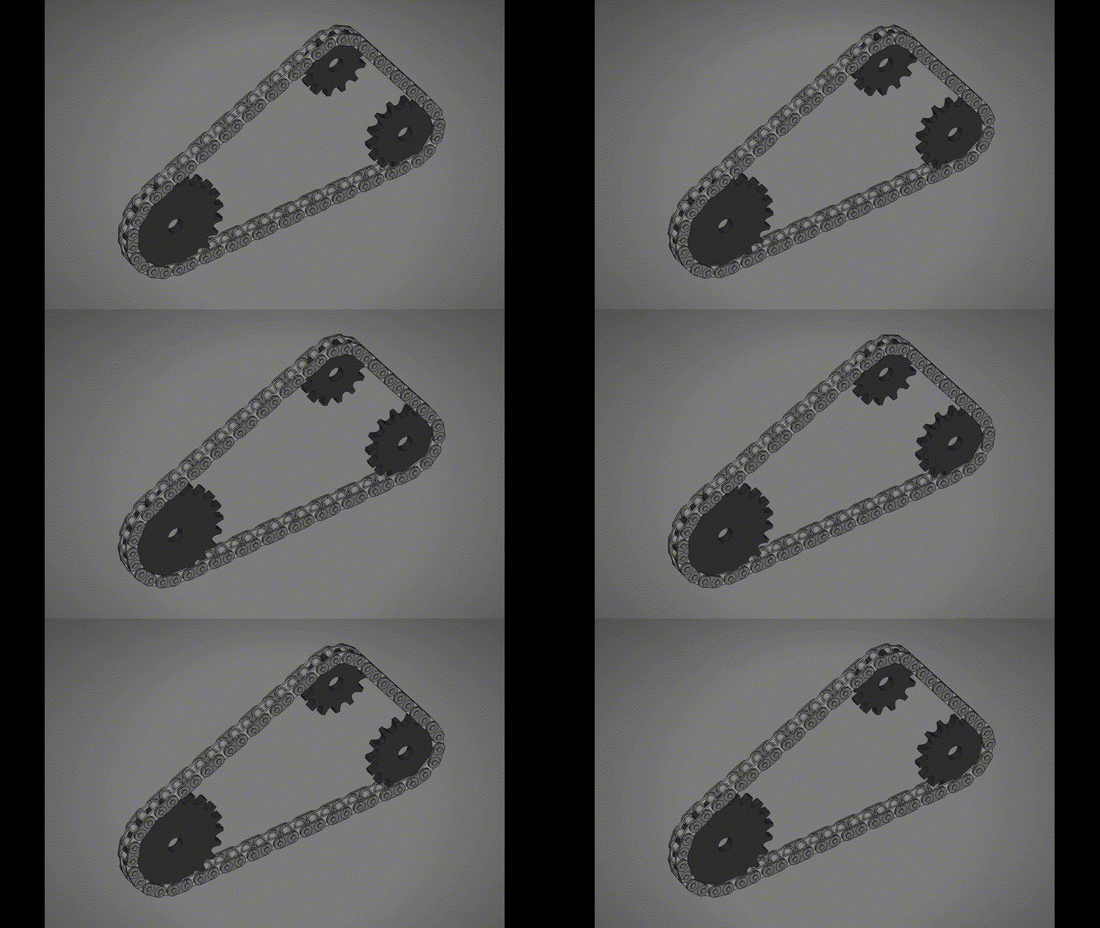
First Macro drawing for FreeCad is just to check it can be done easily. It works. Here is the first Macro:
import FreeCAD as App
import Part
import math
try:
    from PySide import QtCore
except ImportError:
    from PySide6 import QtCore

doc_name = "Chain_Sprocket_13T_15T_Simulation"
doc = App.newDocument(doc_name)

# --- 1. System Parameters ---
t1 = 13 # Left Sprocket Teeth
t2 = 15 # Right Sprocket Teeth
pitch = 9.525
roller_diameter = 6.35
bore_diameter = 10.0
plate_thickness = 5.3
num_links = 32 # Increased chain length to accommodate larger sprocket

# Chain Link Specs
inner_width = 5.72
pin_diameter = 3.28
link_plate_thickness = 1.3

# Calculated Radii
R1 = pitch / (2 * math.sin(math.pi / t1))
R2 = pitch / (2 * math.sin(math.pi / t2))
root1 = R1 - (roller_diameter / 2.0)
root2 = R2 - (roller_diameter / 2.0)

# --- 2. Iterative Solver for Exact Center Distance (C) ---
# A closed chain requires a geometrically perfect loop length.
L_target = num_links * pitch
C = 85.0 # Initial guess
for _ in range(50): # Newton-Raphson method for exact distance
    theta = math.asin((R2 - R1) / C)
    L_calc = 2 * C * math.cos(theta) + R1 * (math.pi - 2*theta) + R2 * (math.pi + 2*theta)
    C -= (L_calc - L_target) / (2 * math.cos(theta))

# Final Path Geometry Variables
theta = math.asin((R2 - R1) / C)
L_str = C * math.cos(theta)
L_arc1 = R1 * (math.pi - 2 * theta)
L_arc2 = R2 * (math.pi + 2 * theta)
L_total = L_arc1 + L_arc2 + 2 * L_str

# Tangent Points defining the path layout
T1top = App.Vector(-R1 * math.sin(theta), R1 * math.cos(theta), 0)
T1bot = App.Vector(-R1 * math.sin(theta), -R1 * math.cos(theta), 0)
T2top = App.Vector(C - R2 * math.sin(theta), R2 * math.cos(theta), 0)
T2bot = App.Vector(C - R2 * math.sin(theta), -R2 * math.cos(theta), 0)

# --- 3. Dynamic Sprocket Generator ---
def create_sprocket(name, teeth, R_pitch, R_root):
    R_outer = R_pitch + 2.3 # Scaled OD
    base_cylinder = Part.makeCylinder(R_outer, plate_thickness)
    scale_y = 0.85

    # Parameterized Wedge Cutter to adapt to different radii
    p_root = App.Vector(R_root, 0, 0)
    p_A = App.Vector(R_pitch - 1.6, 2.77 * scale_y, 0)
    p_B = App.Vector(R_pitch - 1.6, -2.77 * scale_y, 0)
    p_M_up = App.Vector(R_pitch + 1.75, 4.5 * scale_y, 0)
    p_M_low = App.Vector(R_pitch + 1.75, -4.5 * scale_y, 0)
    p_3 = App.Vector(R_pitch + 5.1, 5.5 * scale_y, 0)
    p_4 = App.Vector(R_pitch + 5.1, -5.5 * scale_y, 0)

    arc_root = Part.Arc(p_B, p_root, p_A).toShape()
    arc_up = Part.Arc(p_A, p_M_up, p_3).toShape()
    arc_low = Part.Arc(p_4, p_M_low, p_B).toShape()
    line_out = Part.LineSegment(p_3, p_4).toShape()

    wedge_wire = Part.Wire([arc_root, arc_up, line_out, arc_low])
    wedge_solid = Part.Face(wedge_wire).extrude(App.Vector(0, 0, plate_thickness + 2.0))
    wedge_solid.translate(App.Vector(0, 0, -1.0))

    sprocket = base_cylinder
    for i in range(teeth):
        cutter = wedge_solid.copy()
        cutter.rotate(App.Vector(0, 0, 0), App.Vector(0, 0, 1), i * (360.0 / teeth))
        sprocket = sprocket.cut(cutter)

    bore = Part.makeCylinder(bore_diameter / 2.0, plate_thickness + 2.0)
    bore.translate(App.Vector(0, 0, -1.0))

    obj = doc.addObject("Part::Feature", name)
    obj.Shape = sprocket.cut(bore)
    obj.ViewObject.ShapeColor = (0.2, 0.2, 0.2)
    return obj

sprocket_1 = create_sprocket("Sprocket_13T", t1, R1, root1)
sprocket_2 = create_sprocket("Sprocket_15T", t2, R2, root2)
sprocket_2.Placement.Base = App.Vector(C, 0, 0)

# --- 4. Chain Link Geometry ---
def create_link_plate(thickness, z_offset):
    r = 4.0
    cyl1 = Part.makeCylinder(r, thickness, App.Vector(0,0,z_offset))
    cyl2 = Part.makeCylinder(r, thickness, App.Vector(pitch,0,z_offset))
    box = Part.makeBox(pitch, r*2, thickness, App.Vector(0, -r, z_offset))
    return cyl1.fuse(cyl2).fuse(box)

inner_plate_z1 = plate_thickness/2 + inner_width/2
inner_plate_z2 = plate_thickness/2 - inner_width/2 - link_plate_thickness
p1 = create_link_plate(link_plate_thickness, inner_plate_z1)
p2 = create_link_plate(link_plate_thickness, inner_plate_z2)
r1 = Part.makeCylinder(roller_diameter/2, inner_width, App.Vector(0,0, plate_thickness/2 - inner_width/2))
r2 = Part.makeCylinder(roller_diameter/2, inner_width, App.Vector(pitch,0, plate_thickness/2 - inner_width/2))
inner_link_shape = p1.fuse(p2).fuse(r1).fuse(r2)

outer_plate_z1 = inner_plate_z1 + link_plate_thickness + 0.2
outer_plate_z2 = inner_plate_z2 - link_plate_thickness - 0.2
op1 = create_link_plate(link_plate_thickness, outer_plate_z1)
op2 = create_link_plate(link_plate_thickness, outer_plate_z2)
pin_len = (outer_plate_z1 - outer_plate_z2) + link_plate_thickness + 1.0
pin1 = Part.makeCylinder(pin_diameter/2, pin_len, App.Vector(0,0, outer_plate_z2 - 0.5))
pin2 = Part.makeCylinder(pin_diameter/2, pin_len, App.Vector(pitch,0, outer_plate_z2 - 0.5))
outer_link_shape = op1.fuse(op2).fuse(pin1).fuse(pin2)

links = []
for i in range(num_links):
    link_obj = doc.addObject("Part::Feature", f"Link_{i:02d}")
    link_obj.Shape = inner_link_shape if i % 2 == 0 else outer_link_shape
    link_obj.ViewObject.ShapeColor = (0.7, 0.7, 0.7) if i % 2 == 0 else (0.5, 0.5, 0.5)
    links.append(link_obj)

# --- 5. Complex Tangent Kinematics ---
def get_path_pos(d):
    d = d % L_total
    if d < L_arc1:
        # Wrap CCW around S1
        angle = math.pi/2 + theta + (d / R1)
        return App.Vector(R1 * math.cos(angle), R1 * math.sin(angle), 0)
    elif d < L_arc1 + L_str:
        # Straight bottom return
        dist = d - L_arc1
        return T1bot + (T2bot - T1bot) * (dist / L_str)
    elif d < L_arc1 + L_str + L_arc2:
        # Wrap CCW around S2
        dist = d - (L_arc1 + L_str)
        angle = -math.pi/2 - theta + (dist / R2)
        return App.Vector(C + R2 * math.cos(angle), R2 * math.sin(angle), 0)
    else:
        # Straight top feed
        dist = d - (L_arc1 + L_str + L_arc2)
        return T2top + (T1top - T2top) * (dist / L_str)

# --- 6. Animation Engine ---
global anim_offset
anim_offset = 0.0

# Initial phase alignments to nest teeth into the chain
offset_1 = math.degrees(theta) - 13.8
offset_2 = math.degrees(-theta) + 12.0

def update_simulation():
    global anim_offset
    anim_offset += 1.0   # Simulation speed.

    # Track discrete link paths
    for i, link in enumerate(links):
        d1 = (i * pitch + anim_offset) % L_total
        d2 = ((i + 1) * pitch + anim_offset) % L_total

        pos1 = get_path_pos(d1)
        pos2 = get_path_pos(d2)

        yaw = math.degrees(math.atan2(pos2.y - pos1.y, pos2.x - pos1.x))
        link.Placement = App.Placement(pos1, App.Rotation(App.Vector(0,0,1), yaw))

    # Rotate independently according to varied geometries and chain speed
    sprocket_1.Placement.Rotation = App.Rotation(App.Vector(0,0,1), math.degrees(anim_offset / R1) + offset_1)
    sprocket_2.Placement.Rotation = App.Rotation(App.Vector(0,0,1), math.degrees(anim_offset / R2) + offset_2)

    App.Gui.updateGui()

doc.recompute()

try:
    import FreeCADGui as Gui
    Gui.activeDocument().activeView().viewAxometric()
    Gui.SendMsgToActiveView("ViewFit")

    App.sim_timer = QtCore.QTimer()
    App.sim_timer.timeout.connect(update_simulation)
    App.sim_timer.start(10)
    App.Console.PrintMessage("Simulation running ........ type 'App.sim_timer.stop()' in Python console to halt.\n")
except Exception:
    pass
Discussions
Become a Hackaday.io Member
Create an account to leave a comment. Already have an account? Log In.