 Akshay Jain
What is the nRF24L01+?
The nRF24L01+ is a low-cost 2.4 GHz wireless transceiver that can both transmit and receive data. The module operates from 1.9 V to 3.6 V and is normally powered from a 3.3 V supply. It supports data rates of 250 Kbps, 1 Mbps, and 2 Mbps, while the SPI interface can operate at speeds up to 8 Mbps.
The standard PCB-antenna version can typically achieve around 50–100 meters in open space, although the actual range depends heavily on the environment, antenna orientation, interference, and data rate. For longer-range applications, versions with a PA, LNA, and external antenna are available and can reach distances of up to around 1 km under suitable open-space conditions.
The module is also designed with low-power operation in mind. It consumes roughly 11.3 mA while transmitting and about 13.5 mA while receiving. Standby and power-down modes reduce consumption significantly, making the device useful for battery-powered wireless projects.
How the nRF24L01+ Works
The nRF24L01+ operates in the 2.4 GHz ISM band, covering frequencies from 2.400 GHz to 2.525 GHz. The available spectrum is divided into 126 selectable RF channels. For two modules to communicate, both devices need to be configured to use the same RF channel and compatible communication settings.
For example, if the transmitter is configured for channel 100, corresponding to 2500 MHz, the receiving module must also be configured for the same channel. Using different channels prevents the modules from receiving each other's packets. This channel-based approach also makes it possible to operate different wireless networks in the same general area.
One particularly useful feature is the nRF24L01+'s Multiceiver capability. A single receiver can communicate with up to six different transmitters using separate data pipes and addresses while operating on the same RF channel. Although six pipes can be configured, only one packet is actually received at a time.
Another important feature is Enhanced ShockBurst. Much of the packet-handling work is performed inside the nRF24L01+ itself. The module handles packet construction, addressing, CRC checking, acknowledgments, and automatic retransmission. If the receiver successfully receives a packet, it can automatically return an acknowledgment. If the transmitter does not receive the expected acknowledgment, the packet can be retransmitted. This makes communication more reliable while reducing the amount of communication-management code required on the Arduino.
nRF24L01+ Module Variants
There are several common physical versions of the nRF24L01+, although they use the same basic transceiver technology. The compact version uses a PCB trace antenna and is generally the most convenient choice for short-range Arduino projects. Its range can reach around 100 meters in open space, but walls and other obstacles can reduce this considerably.
A second version uses an SMA connector with an external antenna. The external antenna can improve signal strength and communication stability, especially where the environment contains obstacles or interference.
The third common version combines an external antenna with a Power Amplifier and Low-Noise Amplifier. The PA increases the strength of the transmitted signal, while the LNA improves the receiver's ability to work with weak incoming signals. These modules are intended for longer-range communication and can reach up to around 1000 meters in suitable open-space conditions.
The different module versions can generally communicate with each other, so an application can use a standard PCB-antenna module on one side and a PA/LNA version on the other when the additional range is useful.
nRF24L01+ Pinout

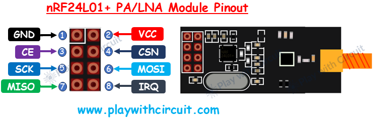
The nRF24L01+ uses an 8-pin interface. GND is the ground connection, while VCC supplies the module with power. The recommended supply voltage is 3.3 V. CE, or Chip Enable, controls the module's active transmit and receive operation. CSN, or Chip Select Not, is the active-low SPI chip-select signal.
The remaining pins are used for SPI communication. SCK carries the SPI clock from the Arduino, MOSI carries data from the Arduino to the nRF24L01+, and MISO carries data from the nRF24L01+ back to the Arduino. The IRQ pin is an optional active-low interrupt output that can be used to notify the microcontroller about events such as received data or transmission status.
Connecting the nRF24L01+ to Arduino UNO

For this experiment, the nRF24L01+ is connected to an Arduino UNO through the SPI interface. The connections remain the same for both the initiating and responding Arduino.
The nRF24L01+ GND pin connects to the Arduino GND, while VCC connects to the Arduino's 3.3 V pin. CE connects to Arduino digital pin 9 and CSN connects to digital pin 10. The SPI clock, SCK, connects to digital pin 13, MOSI connects to digital pin 11, and MISO connects to digital pin 12. The IRQ pin is left unconnected.
The important point here is the power supply. The nRF24L01+ itself is designed for a supply between 1.9 V and 3.6 V, so the bare module should be powered from 3.3 V. Some nRF24L01+ adapter boards include their own regulator and can instead be powered from the Arduino's 5 V supply. It is important to distinguish between the bare RF module and these adapter boards before connecting power.
For a simple prototype, the SPI connections can be made directly as shown above. However, for a more robust or industrial design, appropriate voltage-level considerations should be made when interfacing a 3.3 V wireless module with a 5 V microcontroller.
Two-Way Communication Between Two Arduino Boards
To test the wireless link, I used two Arduino UNO boards, each connected to an nRF24L01+ module. One Arduino acts as the initiator and starts the communication by sending a message. The second Arduino acts as the responder and sends a reply after receiving the message.
The initiator Arduino also has a 16x2 I2C LCD connected to display the communication status.
The responder does not require an LCD and can instead report its received data through the serial interface. This creates a simple wireless handshake between the two boards and provides an easy way to verify that packets are being transmitted and received correctly.

The I2C LCD uses the Arduino UNO's I2C pins. SDA is connected to A4 and SCL is connected to A5, while the LCD's VCC and GND connect to the corresponding Arduino power pins. For the example setup, the LCD uses I2C address 0x27, so the A0, A1, and A2 address jumpers should remain open.
For the wireless communication, the same nRF24L01+ connections are used on both Arduino boards: GND to GND, VCC to 3.3 V, CE to pin 9, CSN to pin 10, SCK to pin 13, MOSI to pin 11, and MISO to pin 12. IRQ is not connected.
Software Setup
The project can be developed using Arduino IDE version 2.3.4 or later. The LCD portion uses the LiquidCrystal_I2C library by Frank de Brabander, version 1.1.2, while wireless communication is handled using the RF24 library by TMRh20, version 1.5.0.
The RF24 library provides a convenient interface for configuring the nRF24L01+, opening communication pipes, selecting addresses, setting the communication channel, transmitting data, and receiving packets. This avoids having to work directly with the low-level registers of the wireless transceiver.
Multiple Transmitters and One Receiver
The same hardware can also be extended to a multi-node wireless setup. Instead of using only one transmitter and one receiver, multiple nRF24L01+ modules can be configured to send information to a single receiver.
The Multiceiver feature makes this possible by providing multiple logical data pipes, each associated with a different address. The receiver can listen for packets from multiple transmitters while all of them operate on the same RF channel. This approach is useful for projects such as wireless sensor networks where several Arduino-based nodes need to report information to one central controller.
In a practical implementation, each transmitter can be assigned its own communication address. The central Arduino can then identify which node sent a particular packet and process the data accordingly. Since the nRF24L01+ handles packet addressing, acknowledgments, and retransmission internally, the Arduino can concentrate on the application-level data rather than managing the complete RF protocol.
Final Thoughts
The nRF24L01+ is a useful option when an Arduino project needs inexpensive, relatively low-power wireless communication. Its SPI interface makes the hardware connection straightforward, while features such as automatic acknowledgment, retransmission, multiple data pipes, and different data rates provide enough flexibility for everything from a simple two-board experiment to a multi-node wireless system.
I found this setup particularly useful as a starting point for experimenting with wireless Arduino projects because the same basic hardware can be expanded later for remote sensors, wireless controls, and multi-node communication.
For the complete source code, detailed wiring diagrams, and additional testing information, you can refer to Play with Circuit, where the complete nRF24L01+ and Arduino project is documented.