Close
0%
0%

Wireless Game Controller V1

A Fully Functional Working Prototype of an Xinput wireless game controller based on Arduino Nano ESP32.

Similar projects worth following
0 followers
Greetings everyone, and welcome back.
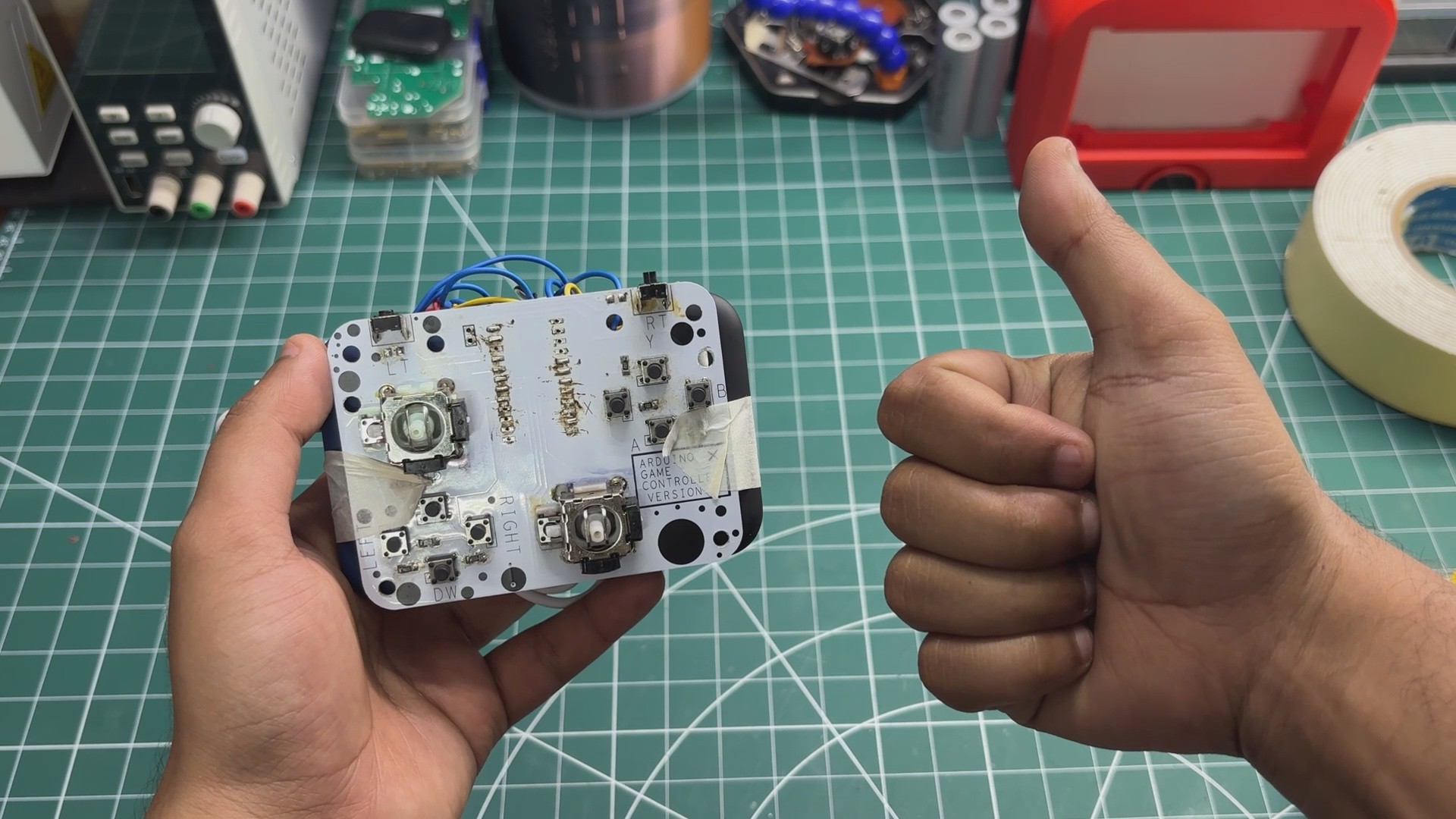
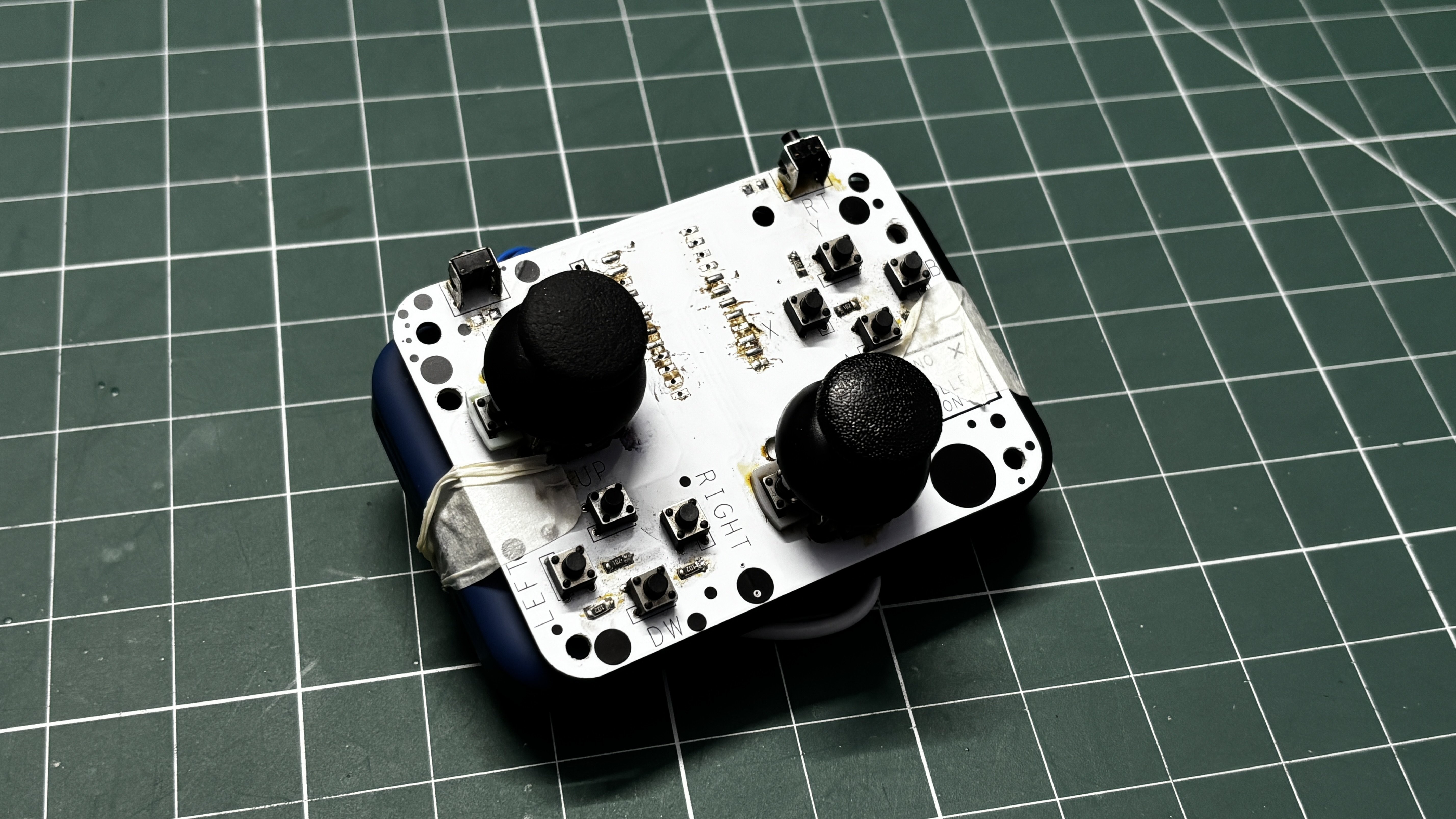
This is my prototype for a wireless Bluetooth game controller built around the Arduino Nano ESP32.

The idea behind this project is to eventually build a completely open-source game controller, from the electronics and PCB to the enclosure and firmware, so that anyone can build their own controller, modify it, or use the design as a starting point for their own projects.

This prototype is the first step towards that goal. I wanted to test the core electronics and make sure I could get a custom controller working wirelessly before designing the final hardware from scratch.

For the prototype, I reused the PCB from a wired game controller I built previously. That board was originally designed around an Arduino Pro Micro and the ATmega32U4. By replacing the Pro Micro with an Arduino Nano ESP32, I can take advantage of the ESP32-S3's built-in Bluetooth Low Energy and turn the same basic controller hardware into a wireless gamepad.

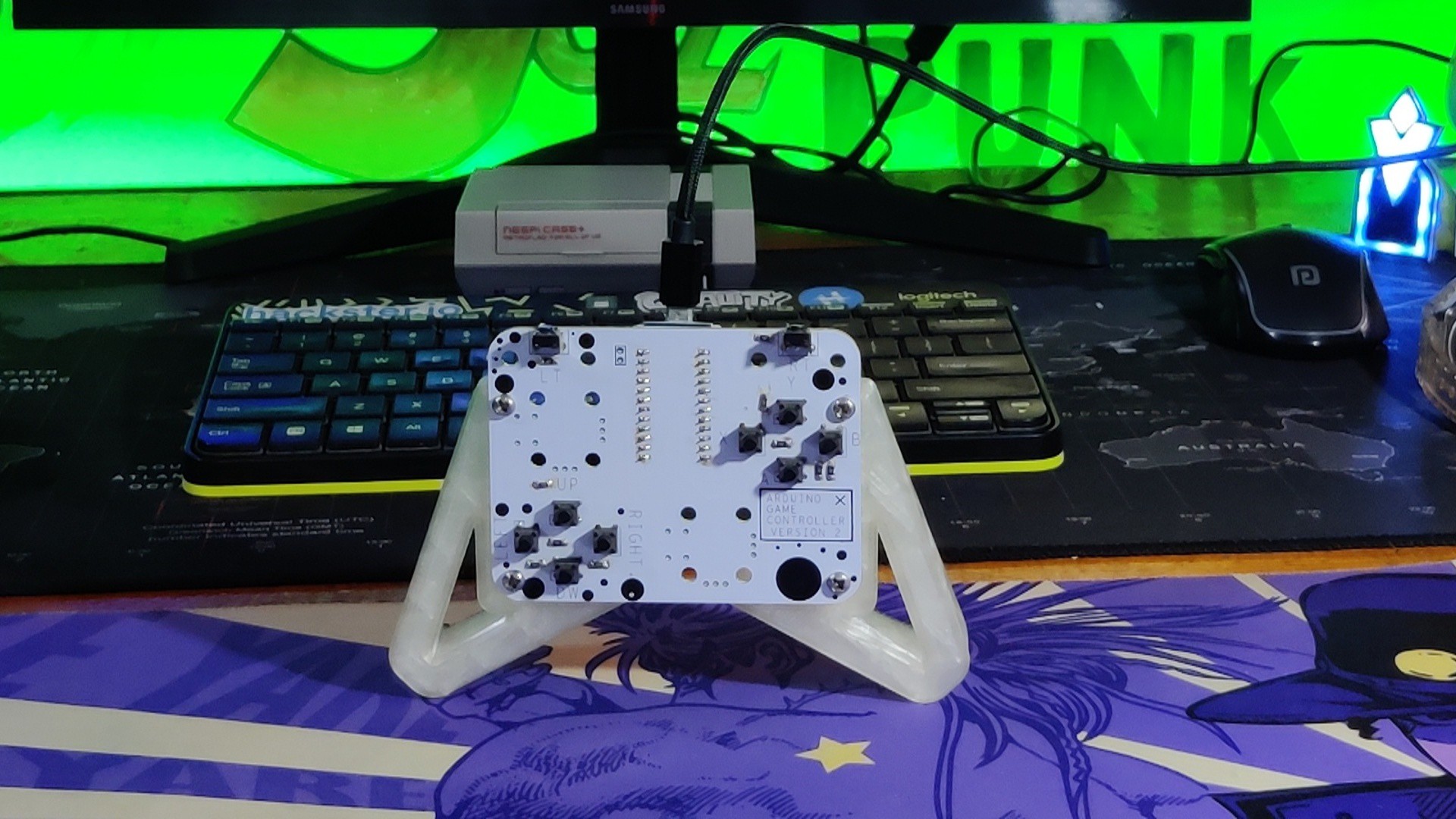
The prototype is already fully functional and can connect to a computer over Bluetooth and work as a regular game controller. I’ve been using it to play games like Cyberpunk 2077 and NieR while testing the hardware and firmware.

This isn't the final controller yet. The eventual version will have a completely custom PCB, a purpose-built enclosure, and a much more refined design. For now, this prototype is about proving that the concept works and laying the groundwork for the open-source controller project.

This article covers the complete build process of this prototype, so let's get started with the build.

MATERIALS REQUIRED

These were the components used in this build

  • Custom PCB (Salvaged from previous Project)
  • Arduino Nano ESP32 Board
  • Right-Angle Push Buttons
  • Horizontal Push Buttons
  • Analog Joysticks
  • Power bank
  • USB to Type C Cable
  • Double-sided tape

HARDWARE—ARDUINO GAME CONTROLLER
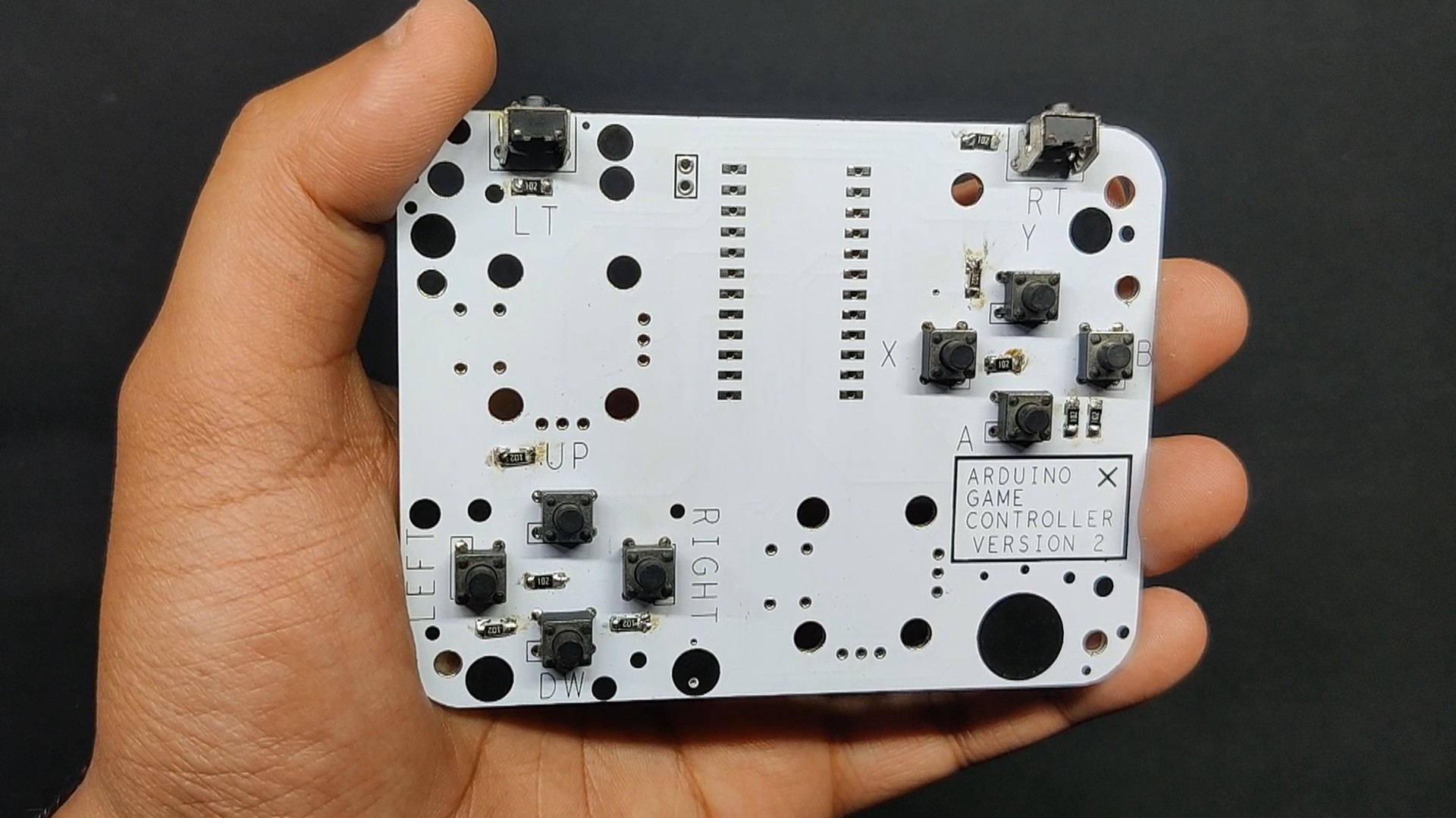
If the Arduino Nano ESP32 is the brain of this project, then the previously made game controller PCB is definitely the brawn.

For this project, I'm reusing the main joystick and button PCB from my previous Arduino game controller project. In the original version, an Arduino Pro Micro was connected to this PCB and acted as the interface between the controller and the PC. Using the ATmega32U4's native USB HID support, I was able to control games and use the board as a regular game controller.

The most interesting part of this controller, however, is that only one I/O pin is used to control all 10 buttons on the board. I achieved this using a clever resistor voltage-divider setup, which allows the microcontroller to identify which button is being pressed by reading different voltage levels from a single analog pin. I'll explain how this works in the next step.

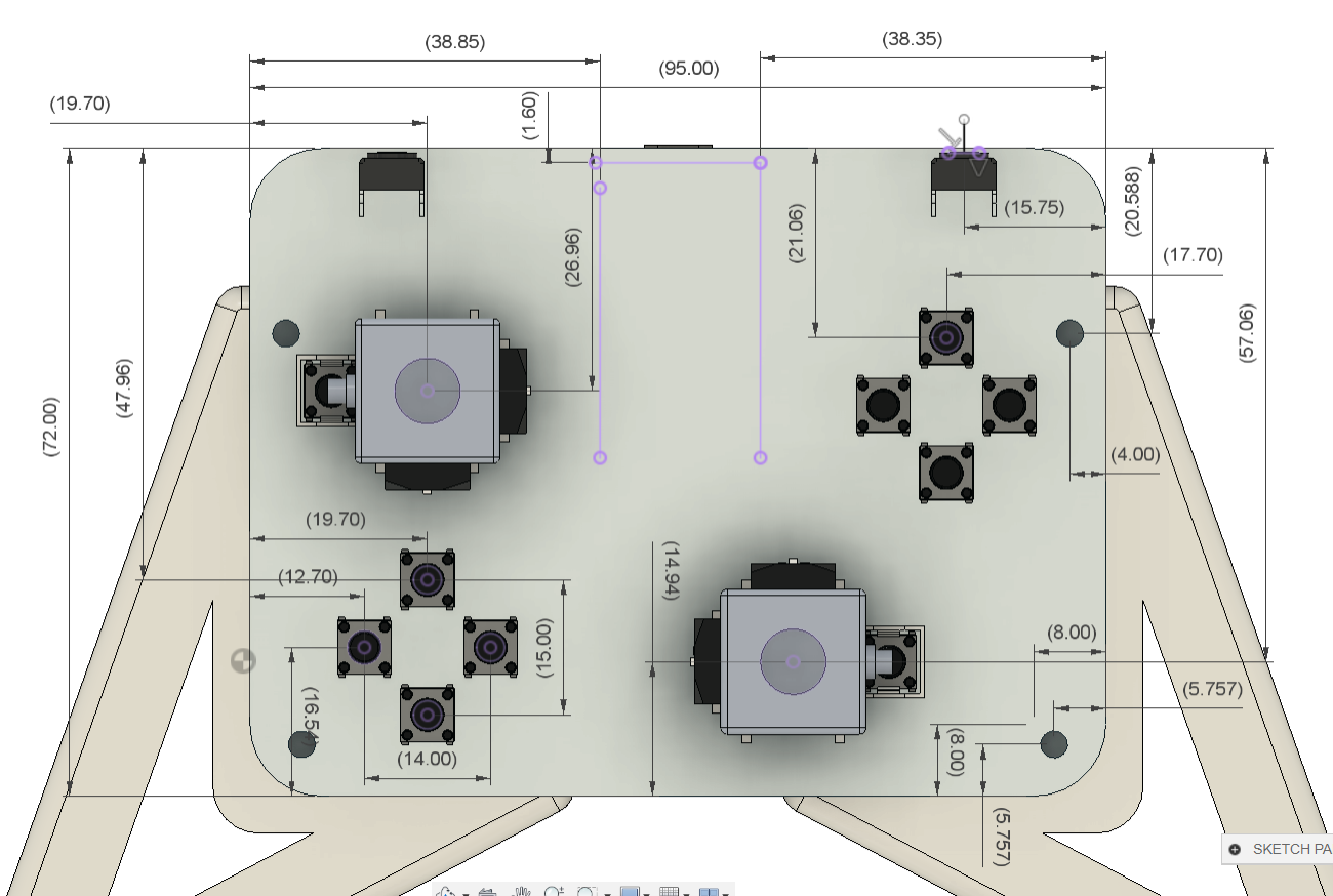
I had also designed this PCB with provisions for two thumbsticks, which is something I was able to take advantage of for this wireless version.

For a more detailed look at the construction and the other design decisions behind the original controller, check out its project page.

https://www.hackster.io/Arnov_Sharma_makes/arduino-retro-game-controller-7cdd0e

PCB DESIGN
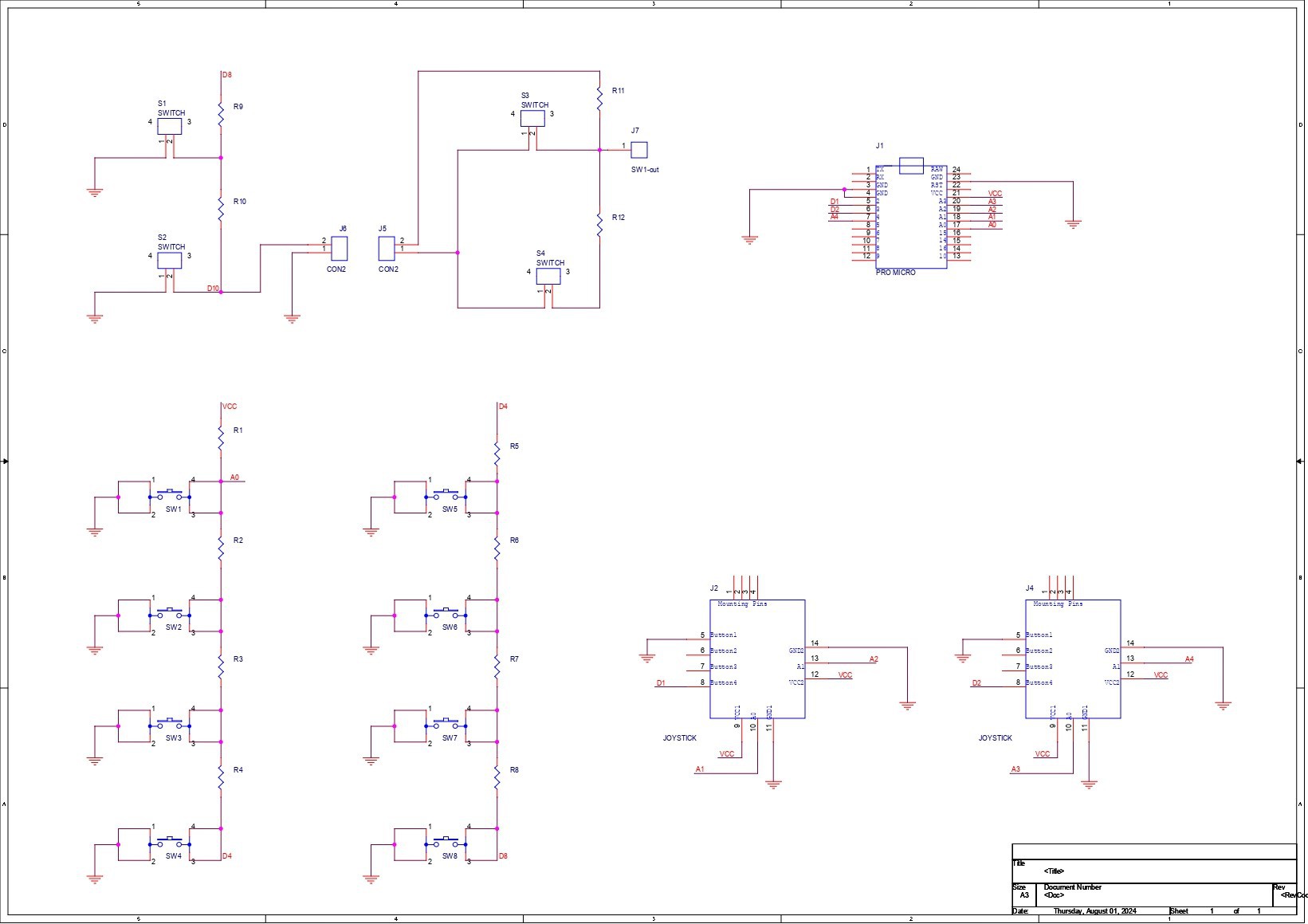
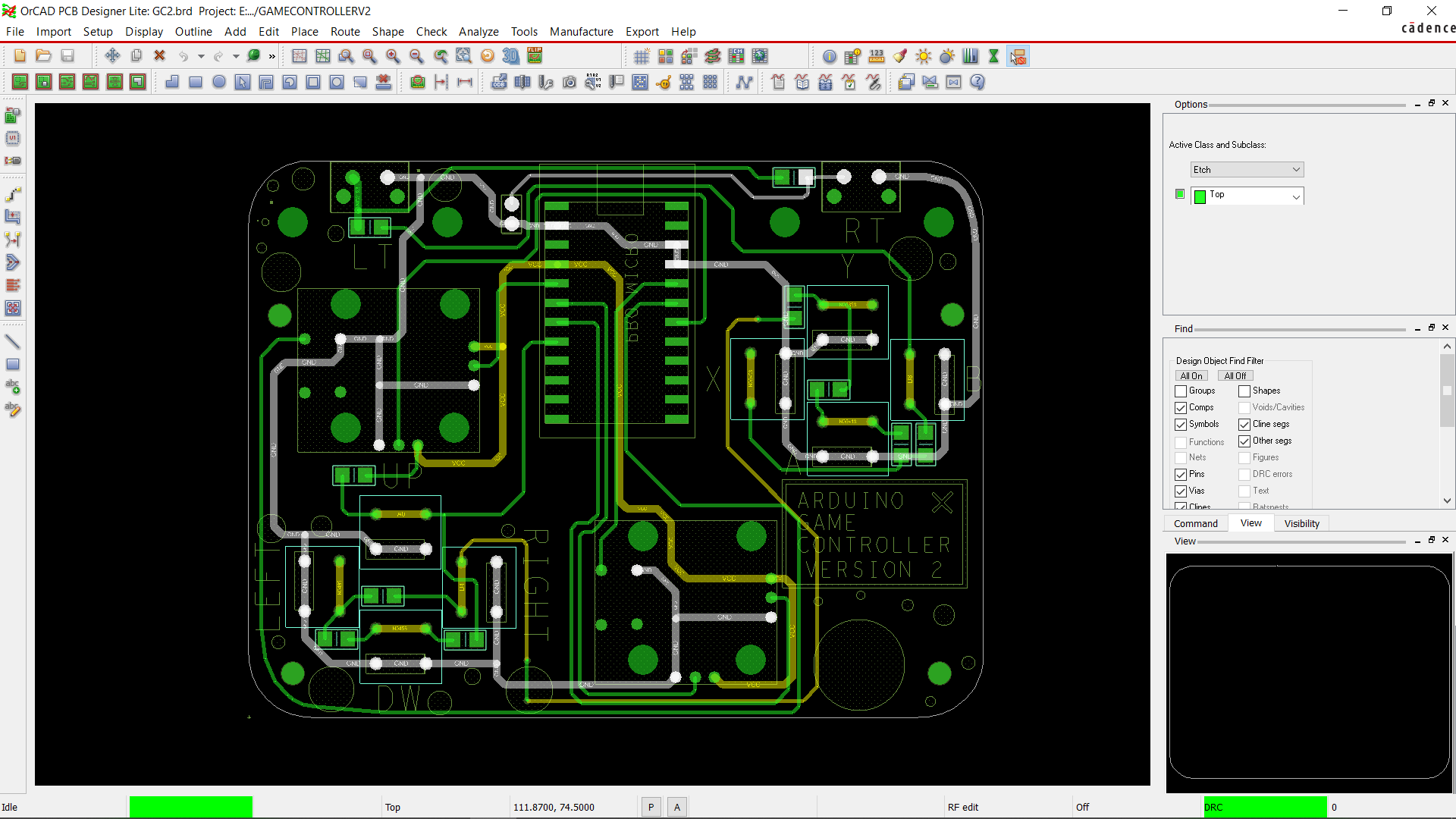
For this project, I made a fairly traditional, straightforward game controller PCB, with the buttons connected to the GPIO pins of a microcontroller that supports HID, since the original version was designed as a wired game controller.

The interesting part is how I managed to connect 10 buttons using a single I/O pin.

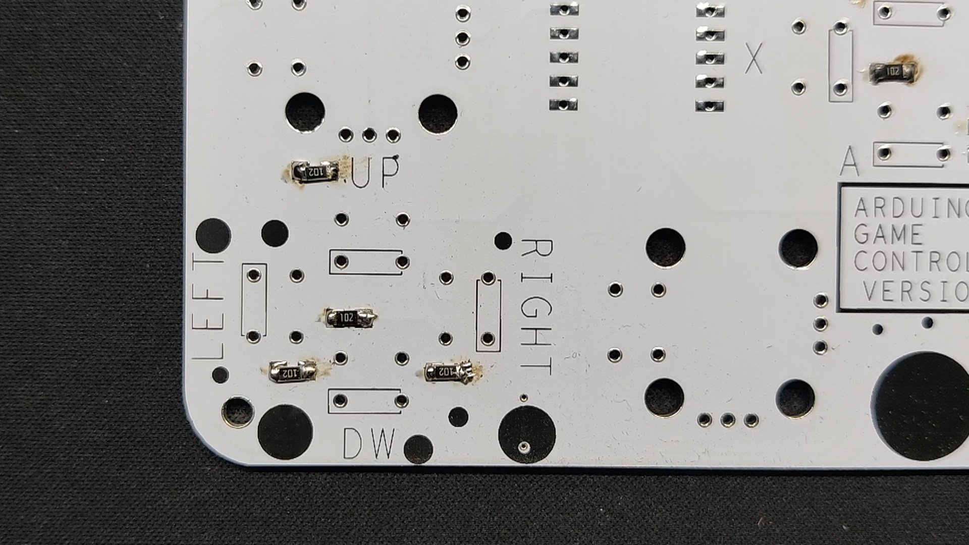
For this, I built a resistor-ladder arrangement using twelve 1 kΩ resistors connected in series between VCC and the button inputs. Each button connects to a different point on the resistor ladder, while the other side of each switch is connected to ground.

When a button is pressed, it produces a different voltage at the shared analog input depending on its position in the resistor ladder. The microcontroller reads this voltage through its ADC and can determine which button was pressed based on the measured value.

This approach makes it possible to connect a large number of buttons to a single analog I/O pin, instead of needing a separate GPIO pin for every button. In practice, you can use this technique to fit 10–20 buttons or even more onto a single input, depending on the resistor values, ADC resolution, and how much tolerance you can accommodate.

PCBWAY SERVICE
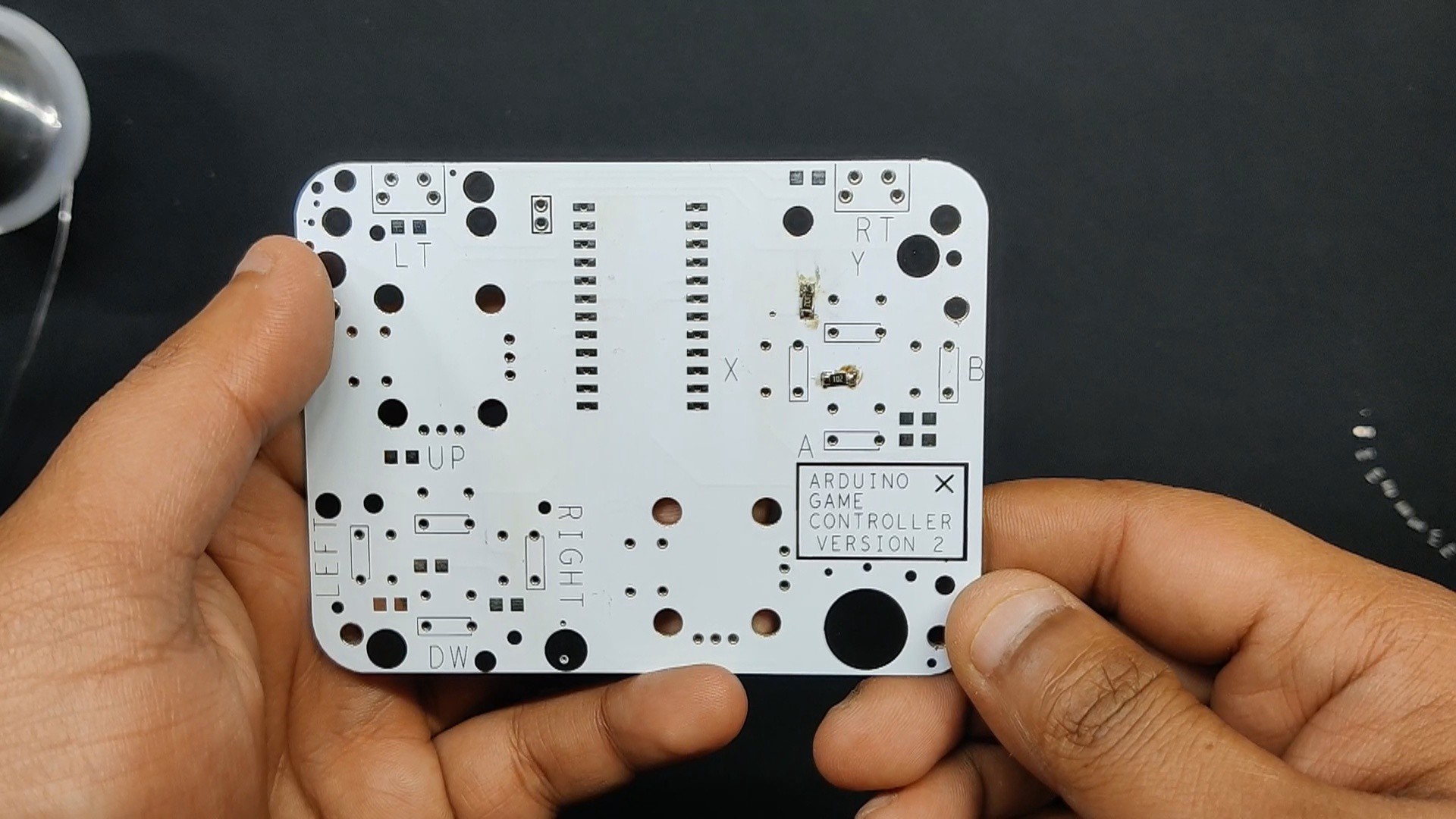
After finalizing the design, I generated the PCB Gerber file and sent them to PCBWay for fabrication. I chose a White PCB with a Black solder mask.

The quality turned out to be excellent with a clean finish and sharp silkscreen, and everything...

Read more »
  • 1
    WIRING

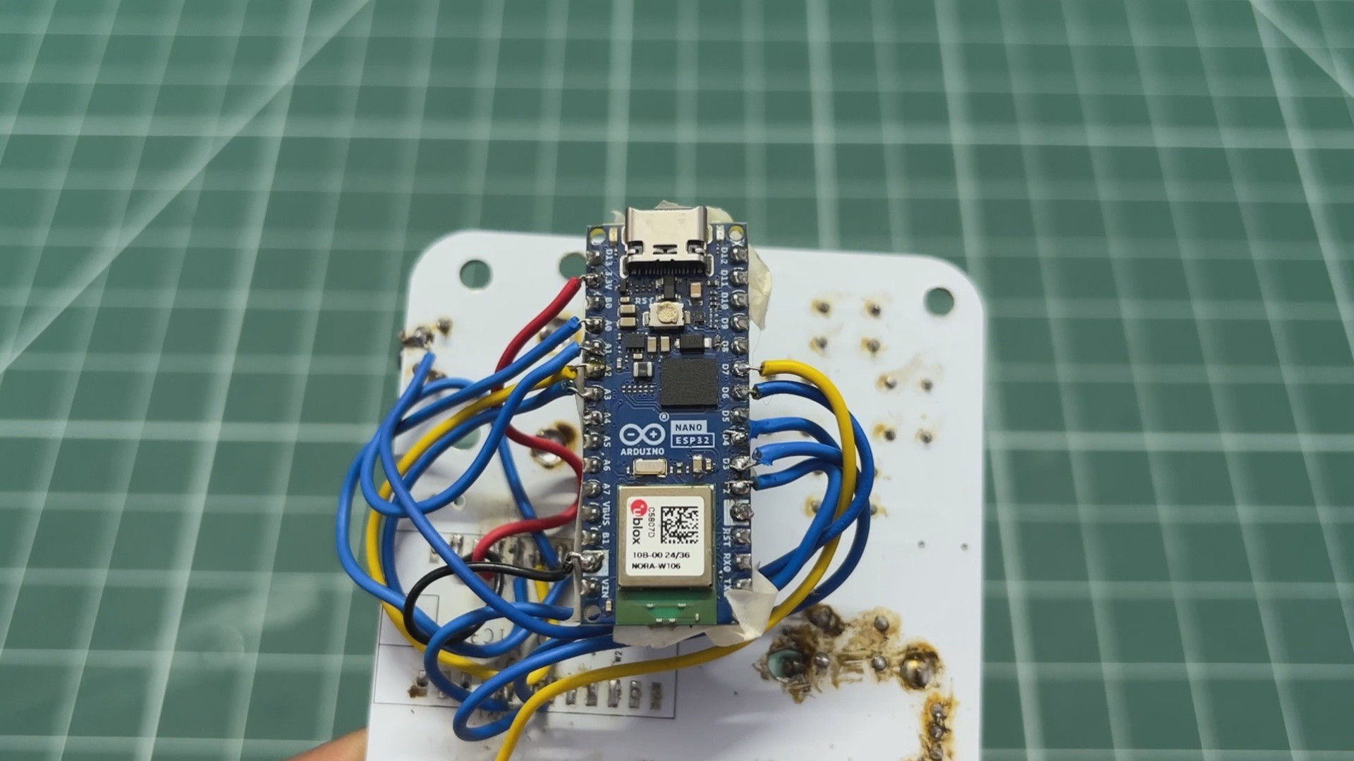
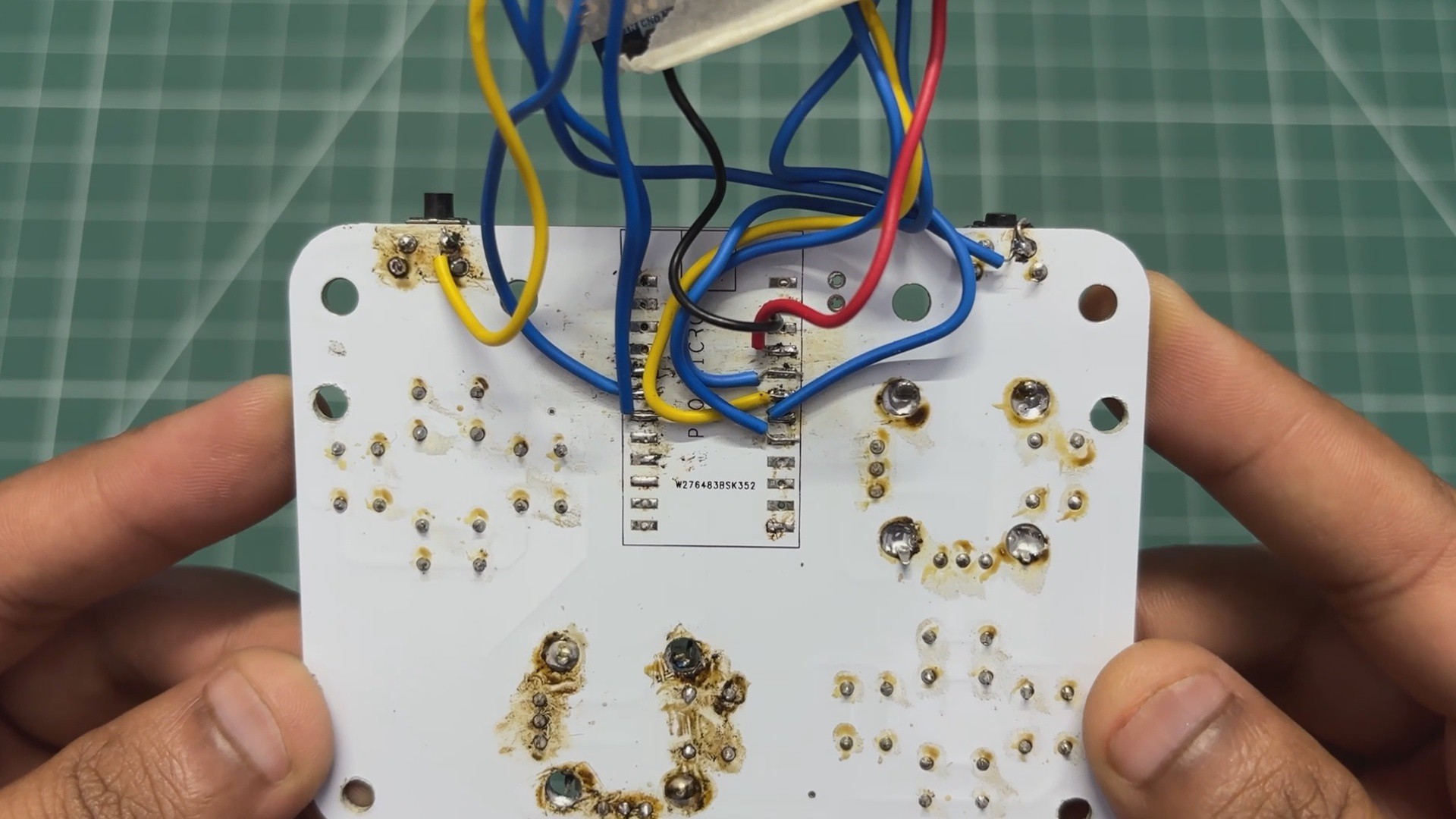
    Wiring this board was quite straightforward. I was able to use a single analog pin for all the A, B, X, Y buttons and D-pad inputs using a resistor ladder, with A0 handling the combined input.

    The rest of the controls were connected as follows:

    • Right joystick Y: A1
    • Right joystick X: A2
    • Left joystick Y: A3
    • Left joystick X: D4
    • Right joystick switch: D2
    • Left joystick switch: D3
    • LT: D6
    • RT: D7

    I initially ran into some issues with the LT and RT inputs, so I ended up connecting them directly to D6 and D7 respectively. For making connections, I use single-core silver copper wire.

  • 2
    CODE

    Here's the main code I used in this project and its a simple one.

    #include <BleGamepad.h>
    BleGamepad bleGamepad("Open-Game-Controller", "Arnov", 100);
    // ---------------------------------------------------------------- amber LED
    const int PIN_LED         = 13;
    const int LED_PWM_CHANNEL = 0;
    const int LED_PWM_FREQ    = 5000;
    const int LED_PWM_RES     = 8;
    // ---------------------------------------------------------------- config
    #define DEBUG_SERIAL 1
    const int MATCH_TOLERANCE = 30;
    const int IDLE_THRESHOLD  = 1000;
    const int SAMPLES        = 8;
    const int STICK_DEADZONE = 40;
    const bool INVERT_LJ_X = false;
    const bool INVERT_LJ_Y = true;
    const bool INVERT_RJ_X = false;
    const bool INVERT_RJ_Y = true;
    const uint32_t DEBOUNCE_MS = 25;
    // ---------------------------------------------------------------- pins
    const int PIN_LADDER = A0;
    const int PIN_RJ_Y   = A1;
    const int PIN_RJ_X   = A2;
    const int PIN_LJ_Y   = A3;
    const int PIN_LJ_X   = D4;
    const int PIN_RJ_SW  = D2;
    const int PIN_LJ_SW  = D3;
    const int PIN_BTN_LT = D6;
    const int PIN_BTN_RT = D7;
    // ---------------------------------------------------------------- mapping
    #define XB_A      BUTTON_1
    #define XB_B      BUTTON_2
    #define XB_X      BUTTON_3
    #define XB_Y      BUTTON_4
    #define XB_LB     BUTTON_5
    #define XB_RB     BUTTON_6
    #define XB_LS     BUTTON_9
    #define XB_RS     BUTTON_10
    #define XB_UP     BUTTON_11
    #define XB_DOWN   BUTTON_12
    #define XB_LEFT   BUTTON_13
    #define XB_RIGHT  BUTTON_14
    struct LadderEntry {
    int value;
    int id;
    const char *name;
    };
    LadderEntry ladder[] = {
    {   0, XB_UP,    "UP"    },
    { 510, XB_DOWN,  "DOWN"  },
    { 681, XB_LEFT,  "LEFT"  },
    { 767, XB_RIGHT, "RIGHT" },
    { 819, XB_Y,     "Y"     },
    { 852, XB_A,     "A"     },
    { 877, XB_X,     "X"     },
    { 900, XB_B,     "B"     }
    };
    const int LADDER_COUNT = sizeof(ladder) / sizeof(ladder[0]);
    // ---------------------------------------------------------------- state
    int ljXCentre = 512, ljYCentre = 512;
    int rjXCentre = 512, rjYCentre = 512;
    int      lastLadderId   = -1;
    int      stableLadderId = -1;
    uint32_t ladderChangeMs = 0;
    int      prevSentId     = -1;
    bool prevLS = false, prevRS = false;
    bool prevLT = false, prevRT = false;
    bool prevConnected = false;
    // ---------------------------------------------------------------- helpers
    int readAveraged(int pin) {
    long sum = 0;
    for (int i = 0; i < SAMPLES; i++) sum += analogRead(pin);
    return sum / SAMPLES;
    }
    int matchLadder(int value) {
    if (value >= IDLE_THRESHOLD) return -1;
    int bestId   = -1;
    int bestDist = MATCH_TOLERANCE + 1;
    for (int i = 0; i < LADDER_COUNT; i++) {
    int dist = abs(value - ladder[i].value);
    if (dist < bestDist) {
    bestDist = dist;
    bestId   = ladder[i].id;
    }
    }
    return bestId;
    }
    int16_t axisToBle(int raw, int centre, bool invert) {
    int delta = raw - centre;
    if (abs(delta) < STICK_DEADZONE) return 16384;
    delta += (delta > 0) ? -STICK_DEADZONE : STICK_DEADZONE;
    int span = (delta > 0) ? (1023 - centre - STICK_DEADZONE)
    : (centre - STICK_DEADZONE);
    if (span < 1) span = 1;
    long scaled = (long)delta * 16383 / span;
    if (scaled >  16383) scaled =  16383;
    if (scaled < -16383) scaled = -16383;
    if (invert) scaled = -scaled;
    return (int16_t)(16384 + scaled);
    }
    float axisMagnitude(int raw, int centre) {
    int delta = abs(raw - centre);
    if (delta < STICK_DEADZONE) return 0.0f;
    delta -= STICK_DEADZONE;
    int span = max(1023 - centre, centre) - STICK_DEADZONE;
    if (span < 1) span = 1;
    float m = (float)delta / (float)span;
    if (m > 1.0f) m = 1.0f;
    return m;
    }
    void ledSet(uint8_t brightness) {
    ledcWrite(LED_PWM_CHANNEL, brightness);
    }
    // Common anode: LOW = on, HIGH = off.
    void statusLedSet(bool red, bool green, bool blue) {
    digitalWrite(LED_RED,   red   ? LOW : HIGH);
    digitalWrite(LED_GREEN, green ? LOW : HIGH);
    digitalWrite(LED_BLUE,  blue  ? LOW : HIGH);
    }
    // ---------------------------------------------------------------- setup
    void setup() {
    #if DEBUG_SERIAL
    Serial.begin(115200);
    #endif
    analogReadResolution(10);
    analogSetAttenuation(ADC_11db);
    pinMode(PIN_LADDER, INPUT);
    pinMode(PIN_LJ_SW,  INPUT_PULLUP);
    pinMode(PIN_RJ_SW,  INPUT_PULLUP);
    pinMode(PIN_BTN_LT, INPUT_PULLUP);
    pinMode(PIN_BTN_RT, INPUT_PULLUP);
    ledcSetup(LED_PWM_CHANNEL, LED_PWM_FREQ, LED_PWM_RES);
    ledcAttachPin(PIN_LED, LED_PWM_CHANNEL);
    ledSet(0);
    pinMode(LED_RED,   OUTPUT);
    pinMode(LED_GREEN, OUTPUT);
    pinMode(LED_BLUE,  OUTPUT);
    statusLedSet(true, false, false);    // red at boot, not connected yet
    delay(400);
    ljXCentre = readAveraged(PIN_LJ_X);
    ljYCentre = readAveraged(PIN_LJ_Y);
    rjXCentre = readAveraged(PIN_RJ_X);
    rjYCentre = readAveraged(PIN_RJ_Y);
    BleGamepadConfiguration cfg;
    cfg.setAutoReport(false);
    cfg.setButtonCount(14);
    cfg.setHatSwitchCount(0);
    cfg.setWhichAxes(true, true, true, false, false, true, false, false);
    cfg.setIncludeStart(true);
    cfg.setIncludeSelect(true);
    bleGamepad.begin(&cfg);
    }
    // ---------------------------------------------------------------- loop
    void loop() {
    bool connected = bleGamepad.isConnected();
    if (connected != prevConnected) {
    statusLedSet(!connected, connected, false);
    prevConnected = connected;
    }
    if (!connected) {
    ledSet(0);
    delay(100);
    return;
    }
    int raw = readAveraged(PIN_LADDER);
    int id = matchLadder(raw);
    if (id != lastLadderId) {
    lastLadderId   = id;
    ladderChangeMs = millis();
    }
    if (millis() - ladderChangeMs >= DEBOUNCE_MS) {
    stableLadderId = id;
    }
    if (stableLadderId != prevSentId) {
    if (prevSentId     >= 0) bleGamepad.release(prevSentId);
    if (stableLadderId >= 0) bleGamepad.press(stableLadderId);
    prevSentId = stableLadderId;
    }
    bool lt = (digitalRead(PIN_BTN_LT) == LOW);
    bool rt = (digitalRead(PIN_BTN_RT) == LOW);
    if (lt != prevLT) { lt ? bleGamepad.press(XB_LB) : bleGamepad.release(XB_LB); prevLT = lt; }
    if (rt != prevRT) { rt ? bleGamepad.press(XB_RB) : bleGamepad.release(XB_RB); prevRT = rt; }
    bool ls = (digitalRead(PIN_LJ_SW) == LOW);
    bool rs = (digitalRead(PIN_RJ_SW) == LOW);
    if (ls != prevLS) { ls ? bleGamepad.press(XB_LS) : bleGamepad.release(XB_LS); prevLS = ls; }
    if (rs != prevRS) { rs ? bleGamepad.press(XB_RS) : bleGamepad.release(XB_RS); prevRS = rs; }
    int ljXRaw = readAveraged(PIN_LJ_X);
    int ljYRaw = readAveraged(PIN_LJ_Y);
    int rjXRaw = readAveraged(PIN_RJ_X);
    int rjYRaw = readAveraged(PIN_RJ_Y);
    bleGamepad.setX (axisToBle(ljXRaw, ljXCentre, INVERT_LJ_X));
    bleGamepad.setY (axisToBle(ljYRaw, ljYCentre, INVERT_LJ_Y));
    bleGamepad.setZ (axisToBle(rjXRaw, rjXCentre, INVERT_RJ_X));
    bleGamepad.setRZ(axisToBle(rjYRaw, rjYCentre, INVERT_RJ_Y));
    bleGamepad.sendReport();
    bool anyButtonHeld = (stableLadderId >= 0) || lt || rt || ls || rs;
    if (anyButtonHeld) {
    ledSet(255);
    } else {
    float ljMag = max(axisMagnitude(ljXRaw, ljXCentre), axisMagnitude(ljYRaw, ljYCentre));
    float rjMag = max(axisMagnitude(rjXRaw, rjXCentre), axisMagnitude(rjYRaw, rjYCentre));
    float mag   = max(ljMag, rjMag);
    ledSet((uint8_t)(mag * 255));
    }
    #if DEBUG_SERIAL
    static uint32_t lastPrint = 0;
    if (millis() - lastPrint > 250) {
    lastPrint = millis();
    Serial.print("ladder "); Serial.print(raw);
    Serial.print("  LT ");   Serial.print(lt);
    Serial.print("  RT ");   Serial.print(rt);
    Serial.print("  LJ ");   Serial.print(ljXRaw); Serial.print("/"); Serial.print(ljYRaw);
    Serial.print("  RJ ");   Serial.print(rjXRaw); Serial.print("/"); Serial.println(rjYRaw);
    }
    #endif
    delay(10);
    }

    It is fairly straightforward, with most of the Bluetooth HID functionality being handled by the BleGamepad library.

    Bluetooth Gamepad Library

    #include <BleGamepad.h>BleGamepad bleGamepad("Open-Game-Controller", "Arnov", 100);

    The BleGamepad library handles the Bluetooth HID side of the project, allowing the Nano ESP32 to identify itself as a wireless game controller.

    The first line includes the library, while the second creates the gamepad instance. Here I have named the controller Open-Game-Controller, set the manufacturer name to Arnov, and set the reported battery level to 100%.

    Controller Configuration

    #define DEBUG_SERIAL 1const int MATCH_TOLERANCE = 30;const int IDLE_THRESHOLD  = 1000;const int SAMPLES        = 8;const int STICK_DEADZONE = 40;const bool INVERT_LJ_X = false;const bool INVERT_LJ_Y = true;const bool INVERT_RJ_X = false;const bool INVERT_RJ_Y = true;const uint32_t DEBOUNCE_MS = 25;

    These variables define some of the basic behaviour of the controller.

    SAMPLES determines how many ADC readings are taken when reading an analog input. I use eight samples and average them to reduce noise.

    STICK_DEADZONE defines how much movement around the joystick's centre position is ignored. This prevents small fluctuations in the joystick from being interpreted as movement.

    The INVERT variables allow me to reverse an axis if the physical orientation of the joystick causes its movement to be interpreted backwards.

    MATCH_TOLERANCE is used for detecting the buttons connected through the resistor ladder, while DEBOUNCE_MS prevents short fluctuations from being interpreted as multiple button presses.

    Pin Mapping

    const int PIN_LADDER = A0;const int PIN_RJ_Y   = A1;const int PIN_RJ_X   = A2;const int PIN_LJ_Y   = A3;const int PIN_LJ_X   = D4;const int PIN_RJ_SW  = D2;const int PIN_LJ_SW  = D3;const int PIN_BTN_LT = D6;const int PIN_BTN_RT = D7;

    This section defines where each physical control is connected to the Nano ESP32.

    The A, B, X, Y buttons and D-pad share A0 through the resistor ladder. The two joysticks use four analog inputs for their X and Y axes.

    The joystick-click switches, LT and RT are connected to digital GPIO pins.

    Mapping the Physical Buttons

    #define XB_A      BUTTON_1#define XB_B      BUTTON_2#define XB_X      BUTTON_3#define XB_Y      BUTTON_4#define XB_LB     BUTTON_5#define XB_RB     BUTTON_6#define XB_LS     BUTTON_9#define XB_RS     BUTTON_10#define XB_UP     BUTTON_11#define XB_DOWN   BUTTON_12#define XB_LEFT   BUTTON_13#define XB_RIGHT  BUTTON_14

    Here I map the physical controls to the button IDs expected by the BleGamepad library.

    For example, pressing the physical A button ultimately results in:

    bleGamepad.press(XB_A);

    which corresponds to BUTTON_1 in the HID gamepad report.

    I am using an Xbox-style button layout for the controller, which makes it compatible with games expecting a standard gamepad.

    The Resistor Ladder

    struct LadderEntry {    int value;    int id;    const char *name;};LadderEntry ladder[] = {    {   0, XB_UP,    "UP"    },    { 510, XB_DOWN,  "DOWN"  },    { 681, XB_LEFT,  "LEFT"  },    { 767, XB_RIGHT, "RIGHT" },    { 819, XB_Y,     "Y"     },    { 852, XB_A,     "A"     },    { 877, XB_X,     "X"     },    { 900, XB_B,     "B"     }};

    This is where the resistor ladder becomes useful.

    Instead of dedicating a separate GPIO pin to every button, each button produces a different voltage that can be measured through the single analog pin A0.

    For example, an ADC reading around 852 represents the A button, while around 900 represents B.

    The controller compares the measured ADC value against this table and selects the closest matching button.

    This allows eight different inputs to share a single analog pin, saving a significant number of GPIOs.

    Averaging Analog Readings

    int readAveraged(int pin) {    long sum = 0;    for (int i = 0; i < SAMPLES; i++)        sum += analogRead(pin);    return sum / SAMPLES;}

    Analog readings are not perfectly stable, so instead of taking one ADC reading, I take eight and calculate their average.

    For example, if the ADC returns:

    850853851854852851853852

    the firmware averages these values before using them.

    This gives us a more stable reading for both the joysticks and the resistor ladder.

    Detecting the Button Ladder

    int matchLadder(int value) {    if (value >= IDLE_THRESHOLD)        return -1;    int bestId = -1;    int bestDist = MATCH_TOLERANCE + 1;    for (int i = 0; i < LADDER_COUNT; i++) {        int dist = abs(value - ladder[i].value);        if (dist < bestDist) {            bestDist = dist;            bestId = ladder[i].id;        }    }    return bestId;}

    This function takes the ADC value from A0 and figures out which button is being pressed.

    If the reading is above the idle threshold, the controller assumes that no button is pressed.

    Otherwise, it checks every value in the resistor ladder table and calculates the distance between the measured value and the expected value.

    The closest match becomes the detected button.

    The tolerance value prevents completely unrelated ADC readings from being treated as a valid button press.

    Converting Joystick Input

    int16_t axisToBle(int raw, int centre, bool invert) {    int delta = raw - centre;    if (abs(delta) < STICK_DEADZONE)        return 16384;    delta += (delta > 0)           ? -STICK_DEADZONE           : STICK_DEADZONE;    int span = (delta > 0)             ? (1023 - centre - STICK_DEADZONE)             : (centre - STICK_DEADZONE);    if (span < 1)        span = 1;    long scaled = (long)delta * 16383 / span;    if (scaled > 16383)  scaled = 16383;    if (scaled < -16383) scaled = -16383;    if (invert)        scaled = -scaled;    return (int16_t)(16384 + scaled);}

    This function converts the raw ADC value from the joystick into the range expected by the Bluetooth HID gamepad.

    The Nano ESP32 gives us a 10-bit ADC value from 0 to 1023, while the HID axis is represented using a larger signed range.

    The function first subtracts the calibrated centre position, applies the deadzone, and then scales the remaining movement.

    The result is approximately:

    Joystick left    → 0Joystick centre  → 16384Joystick right   → 32767

    The invert parameter allows the direction of the axis to be reversed when necessary.

    Initialising the Controller

    void setup() {    Serial.begin(115200);    analogReadResolution(10);    analogSetAttenuation(ADC_11db);    pinMode(PIN_LADDER, INPUT);    pinMode(PIN_LJ_SW, INPUT_PULLUP);    pinMode(PIN_RJ_SW, INPUT_PULLUP);    pinMode(PIN_BTN_LT, INPUT_PULLUP);    pinMode(PIN_BTN_RT, INPUT_PULLUP);

    The setup() function runs once when the controller powers on.

    Here I initialise the Serial connection for debugging, configure the ADC, and set the digital button pins as inputs using the ESP32's internal pull-up resistors.

    Using INPUT_PULLUP means the button reads HIGH when released and LOW when pressed.

    Joystick Calibration

    ljXCentre = readAveraged(PIN_LJ_X);ljYCentre = readAveraged(PIN_LJ_Y);rjXCentre = readAveraged(PIN_RJ_X);rjYCentre = readAveraged(PIN_RJ_Y);

    During startup, the controller measures the resting position of all four joystick axes.

    Instead of assuming the centre is exactly 512, the actual position of each joystick is measured and stored.

    This is useful because real joystick modules aren't perfectly identical and their centre values can vary slightly.

    The only catch is that the joysticks need to be left untouched while the controller is starting up.

    Configuring the Bluetooth Gamepad

    BleGamepadConfiguration cfg;cfg.setAutoReport(false);cfg.setButtonCount(14);cfg.setHatSwitchCount(0);cfg.setWhichAxes(    true, true, true, false,    false, true, false, false);cfg.setIncludeStart(true);cfg.setIncludeSelect(true);bleGamepad.begin(&cfg);

    Here I configure the Bluetooth HID device itself.

    The controller exposes 14 buttons and the required analog axes. I also disable automatic reporting with setAutoReport(false).

    This means the firmware decides when to send the current controller state rather than sending a report every time an individual input changes.

    Once everything is configured, bleGamepad.begin() starts the Bluetooth gamepad.

    The Main Loop

    void loop() {    bool connected = bleGamepad.isConnected();    if (!connected) {        ledSet(0);        delay(100);        return;    }    // Read controller inputs...    bleGamepad.sendReport();    delay(10);}

    The loop() function is where the controller continuously reads its inputs.

    First, it checks whether a Bluetooth device is connected. If there isn't one, it simply waits.

    Once connected, the firmware reads the buttons and joystick positions, processes the inputs, updates the gamepad state, and finally sends the complete report using:

    bleGamepad.sendReport();

    The loop then repeats roughly every 10 milliseconds.

    Reading the Joysticks

    int ljXRaw = readAveraged(PIN_LJ_X);int ljYRaw = readAveraged(PIN_LJ_Y);int rjXRaw = readAveraged(PIN_RJ_X);int rjYRaw = readAveraged(PIN_RJ_Y);bleGamepad.setX(    axisToBle(ljXRaw, ljXCentre, INVERT_LJ_X));bleGamepad.setY(    axisToBle(ljYRaw, ljYCentre, INVERT_LJ_Y));bleGamepad.setZ(    axisToBle(rjXRaw, rjXCentre, INVERT_RJ_X));bleGamepad.setRZ(    axisToBle(rjYRaw, rjYCentre, INVERT_RJ_Y));

    The four joystick axes are read, averaged, converted into HID values, and then assigned to the corresponding gamepad axes.

    The left joystick controls X and Y, while the right joystick is assigned to Z and RZ.

    At this point, the physical movement of the joysticks has been converted into the digital values expected by the Bluetooth gamepad.

    Sending the Final Report

    bleGamepad.sendReport();

    Finally, all the current button and joystick states are sent to the connected device as a Bluetooth HID report.

    The computer therefore doesn't need to know anything about the individual buttons, resistor ladder, joystick ADC values, or the Arduino itself. As far as the operating system is concerned, it is simply communicating with a standard Bluetooth game controller.

    The complete process can be summarised as:

    Physical controls → ADC/GPIO → Input processing → HID values → BleGamepad → Bluetooth → Computer

    And that's essentially how the prototype turns a collection of buttons and analog joysticks into a functional wireless game controller.

  • 3
    POWER SOURCE

    With the firmware flashed, the game controller is ready to go. There is just one problem: it is still wired.

    The controller needs to be powered, and for now, that means connecting a USB Type-C cable to the Nano ESP32.

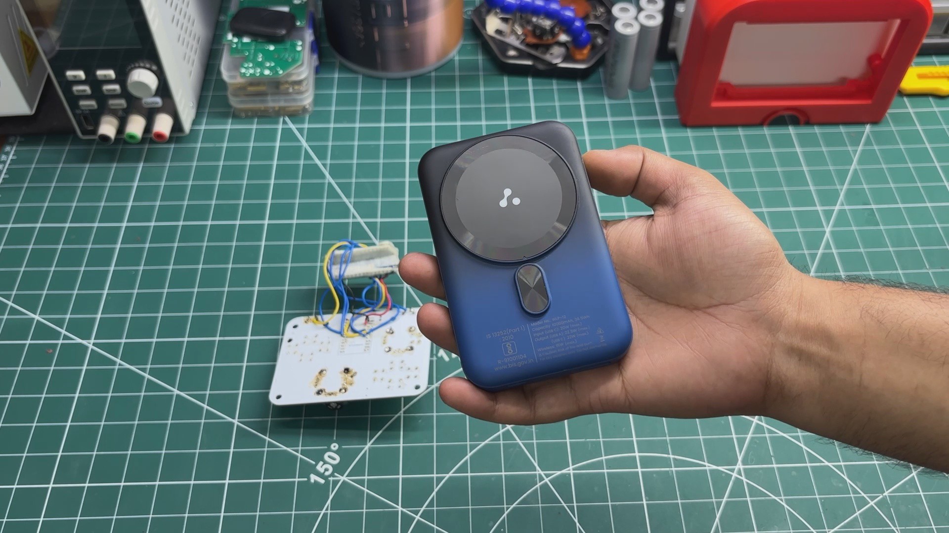
    To get around this temporary limitation, I decided to use a MagSafe power bank. Not because it has MagSafe or anything fancy like that, I just happened to have one lying around.

    The power bank is capable of delivering USB Power Delivery (PD) outputs, but the controller doesn't need anything nearly that complicated. For this prototype, all we need is a regular 5 V supply capable of delivering up to 2 A.

    In reality, the controller should draw considerably less than 2 A. Based on the hardware used in this prototype, the actual consumption should be somewhere around a few hundred milliamps, and potentially even below 200 mA, depending on the operating conditions and connected peripherals.

    For a prototype, though, having a power bank capable of supplying 5 V at 2 A gives us plenty of headroom.

    With the power bank attached to the back, we now have a completely wireless controller, at least until the power bank inevitably becomes the most structurally important part of the entire assembly.

View all 9 instructions

Enjoy this project?

Share

Discussions

Does this project spark your interest?

Become a member to follow this project and never miss any updates