 Srinivasan M S

Project Overview & Objectives
This project is a low-cost, workshop-built cricket bowling machine designed primarily for children practicing with lightweight 65 mm plastic cricket balls.
Built using readily available materials, the working prototype provides consistent ball delivery and incorporates a custom mechanical sequencing system for reliable single-ball feeding.
Beyond standard batting practice, real-world field testing revealed two additional training modes: slip-catching practice and high-catching practice, achieved by tilting the frame upward.
The machine is now considered a completed prototype and will remain unaltered for a 6-to-12-month period to observe its long-term reliability.
Core Requirements
- Target ball: 65 mm lightweight plastic cricket balls.
- Consistency: Reliable, automated single-ball delivery.
- Anti-jamming: Prevent uncontrolled multiple-ball feeding into the propulsion zone.
- DIY architecture: Maintain a simple mechanical layout using commonly available materials and workshop tools.
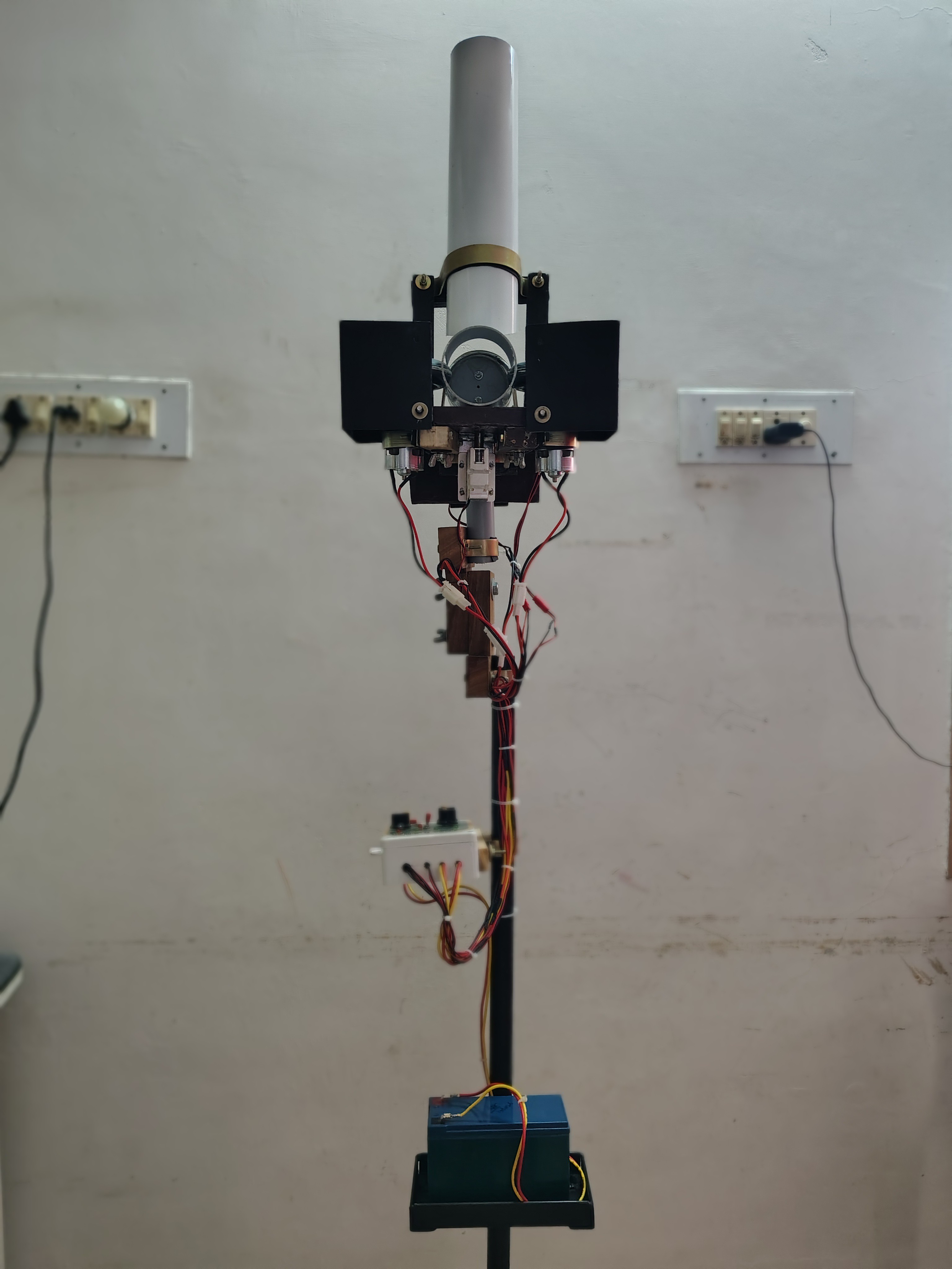
Technical Architecture & Working Principle
The propulsion mechanism uses two high-speed wheels spinning in opposite directions. Driven independently by dedicated RS775 DC motors, the friction generated compresses the ball through a set gap, accelerating it forward. Adjusting individual motor voltages via a 555-timer PWM setup controls ball speed and delivery dynamics.
Component Checklist:
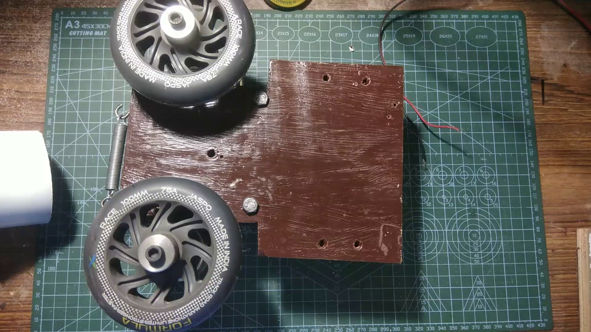
- Propulsion System: 2× RS775 DC Motors, 2× 4" Polyurethane (PU) wheels, custom machined MS hubs, motor clamps, wooden mounting blocks, and rubber isolation pads.
- Feeding Mechanism: 2½" PVC pipe (chute/barrel), custom 1¾" PVC piston, crank disc, linkage arm, and a 30 RPM geared DC motor.
- Sequencing & Power: 12V Solenoid with a blocking pin, boundary micros witches for home-position tracking, 555 PWM controllers, and a 12V 7.2Ah Lead-Acid battery.
- Chassis: Hardwood base plank, heavy-duty metal brackets, adjustment tension springs, and assembly hardware.
Mechanical Evolution & Lessons Learned
1. The Dynamic Wheel Gap Failure (Slow-Motion Video Insight)
- Initial Approach: Tested single and dual spring-loaded pivot arms designed to automatically expand when a ball passed through the wheel nip.
- The Issue: High-speed video analysis revealed that under load, the assemblies didn't just open; they structurally tilted. This unconstrained twisting skewed wheel alignment, ruined energy transfer, and produced inconsistent ball delivery.
- The Fix: Pivoting arms require robust ball bearings to isolate lateral forces. For this DIY build, the complex spring arms were eliminated in favor of a rigid, manually adjusted slotted base that locks tightly into position once the ideal gap is set.
2. Solving High-RPM Wheel Vibration
Severe system noise and structural oscillation threatened early testing. This engineering bottleneck was solved through a systematic overhaul:
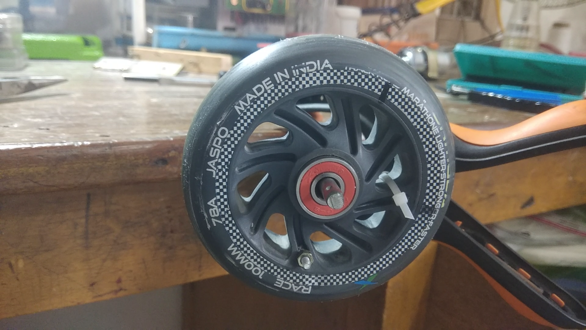
- Material Upgrade: Replaced generic plastic/rubber-tread wheels (which suffered from run-out, delamination, and face wobble) with 4-inch Polyurethane (PU) wheels mounted tightly via machined aluminum couplings.
- DIY Static Balancing Setup: Lacking commercial dynamic balancers, each wheel was set on a free-spinning 6mm shaft supported by low-friction bearings. Gravitational low points identified the heavy zones. The first wheel was permanently counter weighted with a 2.19g bolt/nut combo, and the second with a 1.17g trimmed weight until both stood completely neutral at any clock position.
- Acoustic & Vibration Isolation: Layered sheets of high-density rubber and FR4 load-distribution plates were clamped between the motor bodies and the wooden framing. This limited resonance transmission, rendering the machine nearly vibration-free below 70% speed.

Automatic Single-Ball Feeding Sequence
The mechanical control stack relies on gravity and mechanical timing rather than a microprocessor.
Vertical Gravity Chute
↓
Horizontal...