 Sergei
On 20 September 2026, I reached the first concrete results of the instrument-panel design.
Starting with the most critical parts
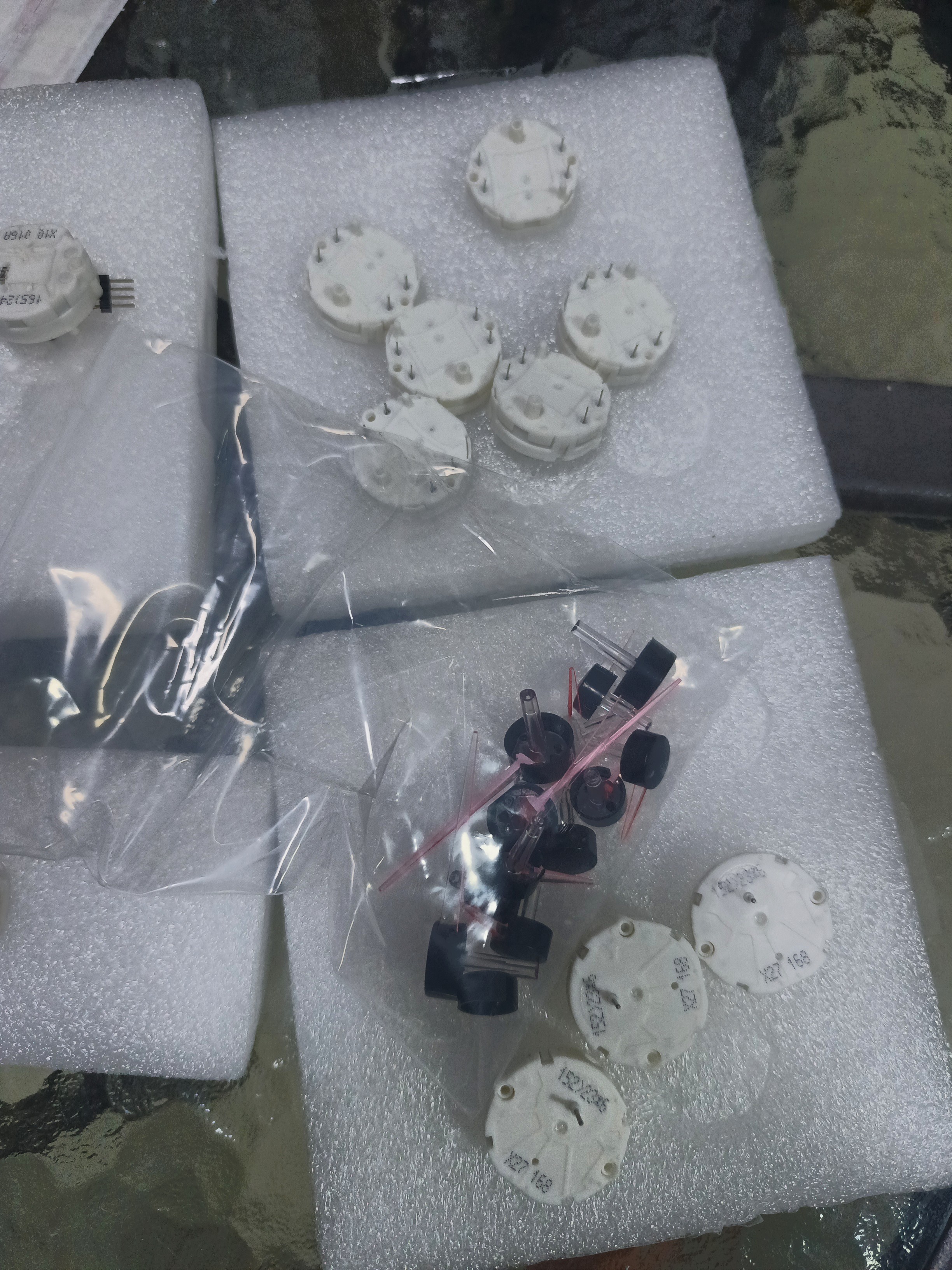
At the start of development, I received the parts that were most critical to my design: the gauge motors and needles ordered from AliExpress. I wanted to base the layout on the actual components, so I carefully measured them and created 3D models for accurate packaging and mechanical design.
I also checked that the motors worked using an Arduino and a very simple sketch.
From measurements to a mechanical layout
Using the measured component models, I put together the first instrument layout in Autodesk Fusion. This lets me work out how the motors, shafts, needles, dial plates and display openings fit together, and check clearances as the design develops.
The exterior render and both Fusion views are available in the project gallery.
How the panel could look on my motorcycle
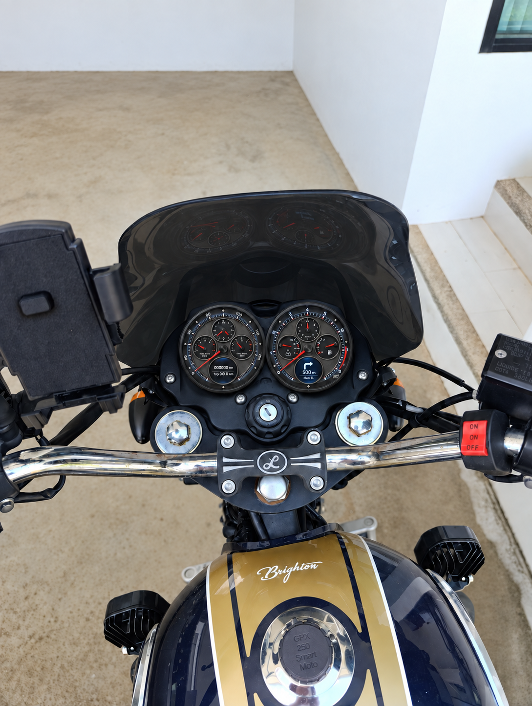
I then made a visual mock-up to get a first impression of how the new panel would look on my GPX 250 Twin. This is an early look at its appearance and proportions from the riding position.
A first electronics architecture
I also drew the first electronics block diagram. The architecture uses an ESP32 main unit connected over RS-485 to two identical STM32F103 instrument modules. Each module has four motors, a display, RTC, an ambient light sensor, its own regulators and two bright LED indicator lamps.
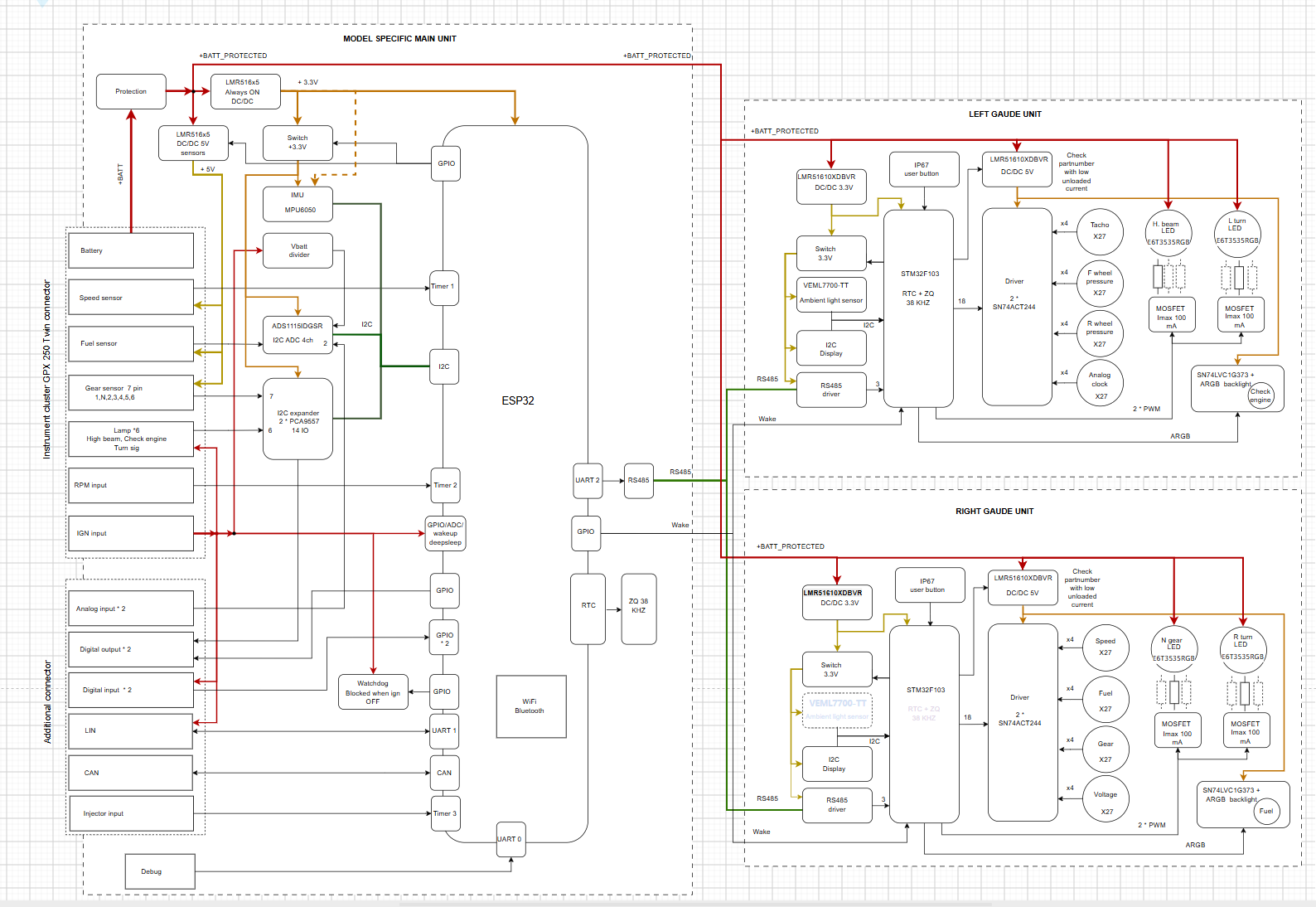
Proposed architecture, first version. Hardware and firmware are still being developed.
What is working, and what is next
The motors have passed an initial functional check. The complete cluster is still in development, with mechanical refinement, electronics and power management next.
The renders communicate the intended appearance, but contain errors introduced by AI. Scales, labels and display graphics still need work. The speedometer/tachometer positions also differ between the exterior render and the block diagram; I will reconcile these as the design develops.
Follow the full development log at dashboard.smartmoto.asia. Documentation and design images are in the project repository.
Discussions
Become a Hackaday.io Member
Create an account to leave a comment. Already have an account? Log In.